EP1584412A2 - Sander with vertical handle - Google Patents
Sander with vertical handle Download PDFInfo
- Publication number
- EP1584412A2 EP1584412A2 EP05007263A EP05007263A EP1584412A2 EP 1584412 A2 EP1584412 A2 EP 1584412A2 EP 05007263 A EP05007263 A EP 05007263A EP 05007263 A EP05007263 A EP 05007263A EP 1584412 A2 EP1584412 A2 EP 1584412A2
- Authority
- EP
- European Patent Office
- Prior art keywords
- housing
- sander
- gripping
- gripping member
- handle
- Prior art date
- Legal status (The legal status is an assumption and is not a legal conclusion. Google has not performed a legal analysis and makes no representation as to the accuracy of the status listed.)
- Withdrawn
Links
Images


Classifications
-
- B—PERFORMING OPERATIONS; TRANSPORTING
- B24—GRINDING; POLISHING
- B24B—MACHINES, DEVICES, OR PROCESSES FOR GRINDING OR POLISHING; DRESSING OR CONDITIONING OF ABRADING SURFACES; FEEDING OF GRINDING, POLISHING, OR LAPPING AGENTS
- B24B23/00—Portable grinding machines, e.g. hand-guided; Accessories therefor
Definitions
- the present invention relates to sanders and, more particularly, but not exclusively to random orbital sanders having multiple gripping members, including a spaced vertical handle.
- Orbital sanders generally include a vertically orientated housing having a handle at an axial end of the housing. Thus, the handle is positioned above the orbital sanding element so that a workman applies force directly onto the orbital sanding element.
- These handles have various types of designs in order to accommodate the workman's hand.
- orbital sanders exist which include handles which extend from the housing substantially perpendicular to the orbital sander housing. These types of handles are in a horizontal orientation. Thus, during use, for a significant period of time, vibration can cause the user's hand to become fatigue. Accordingly, it is desirable to have an orbital sander which enables the user various gripping orientations to overcome the shortcoming of the prior art.
- the present invention provides the art with a orbital sander that provides multiple gripping positions.
- the orbital sander provides the user with a gripping surface spaced from the housing and substantially parallel to the housing.
- the present invention provides the user with a gripping portion which surrounds the housing to provide a 360 degree handle for various orientations of the orbital sander.
- the present invention provides the user with a palm grip having a gel portion to reduce vibration in the tool.
- the present invention also enables the user to utilize both hands at various positions on the sander during operation.
- an orbital sander comprises a housing with an overall axial orientation.
- a motor is positioned within the housing.
- An output is coupled with the motor to drive the orbital sanding element.
- a power source is coupled with the motor.
- An activation member is coupled with the motor and the power source. The activation member energizes and de-energizes the motor which, in turn, randomly rotates the output and sanding element.
- a handle having an overall vertical orientation is spaced from the housing.
- the housing ordinarily has a cylindrical portion and a truncated conical portion adjacent the cylindrical portion.
- a gripping member is positioned at the intersection of the cylindrical portion and a truncated conical portion. The gripping member surrounds a portion of the housing.
- the gripping member that surrounds the housing is formed from an elastomeric material providing comfort and feel for the user.
- a gripping member maybe positioned on an end of the housing opposing the output. This gripping member may include a gel portion.
- an orbital sander comprises a housing that has an overall axial orientation with two ends.
- a motor is positioned within the housing.
- An output coupled with the motor, is positioned at one of the ends of the housing to drive a sanding element.
- a power source is coupled with the motor.
- An activation member is coupled with the motor and the power source to energize and de-energize the motor which, in turn, drives the output and the sanding element.
- a gripping member surrounds the housing.
- the gripping member is positioned between the ends of the housing.
- the gripping member is elastomeric to provide comfort and feel.
- the gripping member is continuous 360 degrees around the housing.
- the gripping member has an annular portion and an extending tail portion. The gripping member is positioned on a truncated conical portion of the housing.
- an orbital sander comprises a housing having an axial orientation with a pair of ends.
- a motor is positioned within the housing.
- An output, coupled with the motor, is positioned at one of the end to drive a sanding element.
- a power source is coupled with the motor.
- An activation member is coupled with the motor and the power source to energize and de-energize the motor which, in turn, drives the output and the sanding element.
- a plurality of gripping members are coupled with the housing. At least one gripping member is spaced from and positioned substantially parallel to the housing. The one gripping member is a handle. The others of the gripping members are on the housing. One of the gripping members surrounds a portion of the housing. One of the gripping members is positioned on the end of the housing opposing the output.
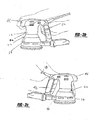
- an orbital sander is illustrated and designated with the reference numeral 10.
- the orbital sander includes a housing 12, a motor 14 positioned within the housing, an output 16 driven by the motor 14, and a platen or carrier 18 that is coupled to the output and oscillatingly driven.
- a sanding element (not shown) is attached to the carrier 18. It should be understood that a polishing or other similar element, other than a sanding element, may be attached to carrier 18 and still be within the scope of the invention.
- a dust collection system 20 is coupled with the housing 12. Also, a plurality of gripping members 22, 24, and 26 are coupled with the housing. An AC power cord 28 is coupled with the housing to provide power to the motor 14. An activation member 30 is coupled with the housing to energize and de-energize the motor 14, in turn, the output 16 which, in turn, rotates the carrier 18.
- the housing 12 defines a central axis 13 and is normally used in a vertical orientation.
- the housing 12 includes a cylindrical portion 32 and a truncated conical portion 34 positioned on axis 13.
- the truncated conical portion 34 at its end includes a skirt 36.
- the skirt 36 provides durability and protects the work surface while sanding.
- a housing gripping member 22 is positioned at the intersection of the cylindrical portion 32 and the truncated conical portion 34.
- the housing gripping member 22 includes an annular portion comprising a gripping surface 40 and a tail surface 42.
- the gripping surface 40 surrounds the housing providing a 360 degree grip on the housing.
- the gripping surface 40 is positioned at the other end of the truncated conical portion 34 wherein it intersects the cylindrical portion 32.
- the tail surface 42 extends from the gripping surface 40 towards the skirt 36.
- the housing gripping member 22 is an elastomeric member and may be over molded onto the housing 12. The elastomeric member provides a comfortable grip as well as increased feel to the user.
- the other end of the housing 12 includes an upper gripping member 24.
- the extending end of the cylindrical portion 32 has a teardrop shaped head 44 with the upper gripping member 24 positioned on top of the head 44.
- the upper gripping member 24 has a teardrop shape and is formed from a gel material that forms an upper gripping surface.
- the gel provides a top surface to absorb vibration of the sander to increase the comfort and/or duration of use by the user without fatigue.
- axis 13 is located substantially centrally relative to the sander housing 12 throughout its entire extent. That is, axis 13 is centrally located with respect to all of upper gripping member 24, cylindrical portion 32 and conical portion 34. Further, as evident with reference to Figs. 3a and 3c, upper gripping member 24 defines an outer perimeter such that a downward projection of the outer perimeter defines a volume in which the housing 12 is substantially disposed within throughout its entire extent. In other words, the middle and lower parts of housing 12 do not extend outwardly of upper gripping member 24 for any substantial extent.
- a handle gripping member 26 is spaced from the housing 12.
- the handle gripping member 26 runs substantially parallel to the housing 12, and has a vertical orientation enabling the user to grip handle gripping member 26 to provide a different orientation for the user's hands.
- the gripping orientations are illustrated in Figures 2a-2e. Also, the user may use two hands when gripping the handle gripping member 26 with another one of the gripping members 22 or 24.
- the handle gripping member 26 is ordinarily formed with the housing 12 to provide a clamshell type of housing member.
- the handle gripping member 26 includes gripping surface 46 and 48 on each of its sides.
- the gripping surfaces 46 and 48 are similar to gripping surface 40, and made of an elastomeric material to provide comfort and feel to the user.
- An open space is formed between gripping surfaces 46, 48 and housing 12 to allow for gripping of the gripping surfaces, with the user's hand oriented in a substantially vertical orientation, as explained below.
- a user may grip the orbital sander at gripping member 22, 24 or 26. This allows the user to vary his hand positions to reduce fatigue during prolonged operation. Also, the user may use a plurality of the gripping members at one time. The user may use grips 22 and 26, 24 and 26, or 22 and 24 at one time to add increased control to the sander during operation.
- the sander may be gripped with two hands utilizing various combinations of grips 22, 24 and 26, the preferred overall configurations and weight allow for the sander to be operated by the user with one hand by solely gripping upper grip 24.
- the user's hand may extend substantially over the entire extent of the sander housing 12. In such a configuration, the user's palm rests substantially in a horizontal plane.
- One advantage provided by this invention is that in addition to allowing for such overhanded gripping at the top of the sander, the user also can grip the sander with his second hand gripping spaced handle 26.
- the user grips gripping surfaces 46 and 48 of handle 26 such that the palm of the second hand is disposed substantially vertically and therefore perpendicular to the palm of the first hand, to provide increased control during operation.
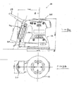
- the weight of the orbital sander may be approximately 3.5 pounds.
- the handle 26 need not be disposed precisely perpendicular to the gripping surface of upper grip 24, that is, it need not be disposed precisely vertical.
- handle 26 and thus gripping surfaces 46 and 48 may be disposed substantially vertically at 103.46° to the horizontal gripping surface of upper grip 24, and thus at an angle of 13.46° to the vertical axis of housing 12. Prefereably, this angle may be varied within a range of 5°.
- Figures 4a and 4b show a second embodiment of the invention, where the carrier 18, and consequently the sanding element (not shown), is rectangular shaped.
- the orbital sander shown in Figures 4a and 4b is a 1 ⁇ 4 sheet sander, with the approximate dimension of the sander shown in millimeters.
Abstract
Description
- The present invention relates to sanders and, more particularly, but not exclusively to random orbital sanders having multiple gripping members, including a spaced vertical handle.
- Orbital sanders generally include a vertically orientated housing having a handle at an axial end of the housing. Thus, the handle is positioned above the orbital sanding element so that a workman applies force directly onto the orbital sanding element. These handles have various types of designs in order to accommodate the workman's hand. Also, orbital sanders exist which include handles which extend from the housing substantially perpendicular to the orbital sander housing. These types of handles are in a horizontal orientation. Thus, during use, for a significant period of time, vibration can cause the user's hand to become fatigue. Accordingly, it is desirable to have an orbital sander which enables the user various gripping orientations to overcome the shortcoming of the prior art.
- The present invention provides the art with a orbital sander that provides multiple gripping positions. The orbital sander provides the user with a gripping surface spaced from the housing and substantially parallel to the housing. Also, the present invention provides the user with a gripping portion which surrounds the housing to provide a 360 degree handle for various orientations of the orbital sander. Also, the present invention provides the user with a palm grip having a gel portion to reduce vibration in the tool. The present invention also enables the user to utilize both hands at various positions on the sander during operation.
- According to a first aspect of the invention, an orbital sander comprises a housing with an overall axial orientation. A motor is positioned within the housing. An output is coupled with the motor to drive the orbital sanding element. A power source is coupled with the motor. An activation member is coupled with the motor and the power source. The activation member energizes and de-energizes the motor which, in turn, randomly rotates the output and sanding element. A handle having an overall vertical orientation is spaced from the housing. The housing ordinarily has a cylindrical portion and a truncated conical portion adjacent the cylindrical portion. A gripping member is positioned at the intersection of the cylindrical portion and a truncated conical portion. The gripping member surrounds a portion of the housing. The gripping member that surrounds the housing is formed from an elastomeric material providing comfort and feel for the user. Also, a gripping member maybe positioned on an end of the housing opposing the output. This gripping member may include a gel portion.
- According to a second aspect of the invention, an orbital sander comprises a housing that has an overall axial orientation with two ends. A motor is positioned within the housing. An output, coupled with the motor, is positioned at one of the ends of the housing to drive a sanding element. A power source is coupled with the motor. An activation member is coupled with the motor and the power source to energize and de-energize the motor which, in turn, drives the output and the sanding element. A gripping member surrounds the housing. The gripping member is positioned between the ends of the housing. The gripping member is elastomeric to provide comfort and feel. The gripping member is continuous 360 degrees around the housing. The gripping member has an annular portion and an extending tail portion. The gripping member is positioned on a truncated conical portion of the housing.
- According to a third aspect of the present invention, an orbital sander comprises a housing having an axial orientation with a pair of ends. A motor is positioned within the housing. An output, coupled with the motor, is positioned at one of the end to drive a sanding element. A power source is coupled with the motor. An activation member is coupled with the motor and the power source to energize and de-energize the motor which, in turn, drives the output and the sanding element. A plurality of gripping members are coupled with the housing. At least one gripping member is spaced from and positioned substantially parallel to the housing. The one gripping member is a handle. The others of the gripping members are on the housing. One of the gripping members surrounds a portion of the housing. One of the gripping members is positioned on the end of the housing opposing the output.
From the following detailed description taken in conjunction with the accompanying drawings and subjoined claims, other objects and advantages of the present invention will become apparent to those skilled in the art. - The present invention will become more fully understood from the detailed description and the accompanying drawings, wherein:
- Figure 1 is a perspective view of an orbital sander in accordance with the present invention;
- Figure 2a-2e are side perspective views of Figure 1 with hands shown in phantom for gripping the sander;
- Figure 3a is a side view of the present orbital sander showing its dimensions in millimeters;
- Figure 3b is a bottom view of the present orbital sander showing its dimensions in millimeters;
- Figure 4a is a side view of a second embodiment of the orbital sander having a rectangular sanding element, with dimensions shown in millimeters; and
- Figure 4b is a bottom view of the second embodiment of the orbital sander, with dimensions shown in millimeters.
-
- The following description of the preferred embodiment(s) is merely exemplary in nature and is in no way intended to limit the invention, its application, or uses.
- Turning to the figures, an orbital sander is illustrated and designated with the
reference numeral 10. The orbital sander includes ahousing 12, amotor 14 positioned within the housing, anoutput 16 driven by themotor 14, and a platen orcarrier 18 that is coupled to the output and oscillatingly driven. A sanding element (not shown) is attached to thecarrier 18. It should be understood that a polishing or other similar element, other than a sanding element, may be attached tocarrier 18 and still be within the scope of the invention. - A
dust collection system 20 is coupled with thehousing 12. Also, a plurality of grippingmembers AC power cord 28 is coupled with the housing to provide power to themotor 14. Anactivation member 30 is coupled with the housing to energize and de-energize themotor 14, in turn, theoutput 16 which, in turn, rotates thecarrier 18. - The
housing 12 defines acentral axis 13 and is normally used in a vertical orientation. Thehousing 12 includes acylindrical portion 32 and a truncatedconical portion 34 positioned onaxis 13. The truncatedconical portion 34 at its end includes askirt 36. Theskirt 36 provides durability and protects the work surface while sanding. - A
housing gripping member 22 is positioned at the intersection of thecylindrical portion 32 and the truncatedconical portion 34. Thehousing gripping member 22 includes an annular portion comprising agripping surface 40 and atail surface 42. The grippingsurface 40 surrounds the housing providing a 360 degree grip on the housing. The grippingsurface 40 is positioned at the other end of the truncatedconical portion 34 wherein it intersects thecylindrical portion 32. Thetail surface 42 extends from the grippingsurface 40 towards theskirt 36. Thehousing gripping member 22 is an elastomeric member and may be over molded onto thehousing 12. The elastomeric member provides a comfortable grip as well as increased feel to the user. - The other end of the
housing 12 includes an upper grippingmember 24. The extending end of thecylindrical portion 32 has a teardrop shapedhead 44 with the upper grippingmember 24 positioned on top of thehead 44. The upper grippingmember 24 has a teardrop shape and is formed from a gel material that forms an upper gripping surface. Thus, the gel provides a top surface to absorb vibration of the sander to increase the comfort and/or duration of use by the user without fatigue. -
Vertical axis 13 is located substantially centrally relative to thesander housing 12 throughout its entire extent. That is,axis 13 is centrally located with respect to all of upper grippingmember 24,cylindrical portion 32 andconical portion 34. Further, as evident with reference to Figs. 3a and 3c, upper grippingmember 24 defines an outer perimeter such that a downward projection of the outer perimeter defines a volume in which thehousing 12 is substantially disposed within throughout its entire extent. In other words, the middle and lower parts ofhousing 12 do not extend outwardly of upper grippingmember 24 for any substantial extent. - A
handle gripping member 26 is spaced from thehousing 12. Thehandle gripping member 26 runs substantially parallel to thehousing 12, and has a vertical orientation enabling the user to grip handle grippingmember 26 to provide a different orientation for the user's hands. The gripping orientations are illustrated in Figures 2a-2e. Also, the user may use two hands when gripping thehandle gripping member 26 with another one of the grippingmembers - The
handle gripping member 26 is ordinarily formed with thehousing 12 to provide a clamshell type of housing member. Thehandle gripping member 26 includes grippingsurface surface 40, and made of an elastomeric material to provide comfort and feel to the user. - An open space is formed between
gripping surfaces housing 12 to allow for gripping of the gripping surfaces, with the user's hand oriented in a substantially vertical orientation, as explained below. - During operation, a user may grip the orbital sander at gripping
member grips - Although as discussed above, the sander may be gripped with two hands utilizing various combinations of
grips upper grip 24. As shown in Fig. 2a, in this sole gripping position, the user's hand may extend substantially over the entire extent of thesander housing 12. In such a configuration, the user's palm rests substantially in a horizontal plane. One advantage provided by this invention is that in addition to allowing for such overhanded gripping at the top of the sander, the user also can grip the sander with his second hand gripping spacedhandle 26. In particular, as shown in Fig. 2b, the user grips grippingsurfaces handle 26 such that the palm of the second hand is disposed substantially vertically and therefore perpendicular to the palm of the first hand, to provide increased control during operation. - With reference to Fig. 3a, preferred dimensions in millimeters for the sander are shown. In a preferred embodiment, the weight of the orbital sander may be approximately 3.5 pounds. As shown, the
handle 26 need not be disposed precisely perpendicular to the gripping surface ofupper grip 24, that is, it need not be disposed precisely vertical. For example, in one preferred embodiment handle 26 and thus grippingsurfaces upper grip 24, and thus at an angle of 13.46° to the vertical axis ofhousing 12. Prefereably, this angle may be varied within a range of 5°. - Figures 4a and 4b show a second embodiment of the invention, where the
carrier 18, and consequently the sanding element (not shown), is rectangular shaped. The orbital sander shown in Figures 4a and 4b is a ¼ sheet sander, with the approximate dimension of the sander shown in millimeters. - The description of the invention is merely exemplary in nature and, thus, variations that do not depart from the gist of the invention are intended to be within the scope of the invention. Such variations are not to be regarded as a departure from the spirit and scope of the invention.
Claims (19)
- A sander having multiple gripping members, comprising:a housing having a top portion, a middle portion and a bottom portion, and the middle portion and the bottom portion having substantially the same central vertical axis;a sanding element located at a bottom portion of the housing;a first gripping member comprising a handle spaced apart from the housing and being parallel or substantially parallel to the housing;a second gripping member located at the bottom portion of the housing, the second gripping member extending around the housing and having a outwardly curved shape.
- A sander having multiple gripping members, comprising:a housing having a cylindrical portion and a truncated conical portion, the cylindrical portion and the truncated conical portion concentrically spaced around a vertical axis of the housing with the truncated conical portion extending downwardly from the cylindrical portion;the truncated conical portion including a skirt and a carrier element;a first gripping member including a handle spaced from the housing and oriented parallel to the vertical axis of the housing, the first gripping member having first gripping surfaces thereon; anda second gripping member located on the truncated conical portion and having a curved second gripping surface.
- A sander having multiple gripping members, comprising:a housing having a top portion, a middle portion and a bottom portion, and a vertical axis with at least the middle portion and the bottom portion having the same vertical axis;a handle gripping member spaced apart from the housing and being substantially parallel to the axis;a housing gripping member located substantially on the bottom portion of the housing; anda top gripping member located substantially at the top portion of the housing and having a cushioning material thereon for creating a comfortable gripping surface.
- The sander of claim 1, wherein:the middle portion of the housing is generally a cylindrical portion and the bottom portion of the housing is a truncated conical portion.
- The sander of claim 1 or 2 or 3, wherein:the spacing of the handle from the housing is arranged to allow a user's hand to fit through the space between the handle and the housing to grip the middle portion or the bottom portion of the housing, and the housing is shaped to allow for gripping with a single hand.
- The sander of claim 1 or 2 or 3, further comprising:a third gripping member located at the top portion of the housing and having a gel-like material thereon.
- The sander of claim 6, wherein:the third gripping surface is tear-drop shaped.
- The sander of claim 1 or 2 or 3, further comprising:a dust collection system located at the bottom of the handle and a power cord located at the top of the handle.
- A power driven oscillating tool comprising:a housing, said housing having a longitudinal axis which is situated substantially centrally of said housing for substantially the entire vertical extent of said housing, said housing having an upper gripping surface;a motor disposed in said housing;a carried disposed below said housing and driven to oscillate by said motor;a side gripping surface displaced from said housing so as to form an open space between said side gripping surface and said housing.
- A power driven oscillating tool comprising:a housing having an upper gripping member and a main body portion extending downwardly from said upper gripping member, said upper gripping member defining an outer perimeter, a downward projection of said outer perimeter defining a volume such that said housing is disposed throughout substantially the entire extent of said housing substantially entirely within the defined volume.a motor disposed in said housing;a carrier disposed below said housing and driven to oscillate by said motor; anda side gripping surface displaced from said housing so as to form an open space between said side gripping surface and said housing.
- The tool of claim 9 or 10, wherein the side gripping surface has a longitudinal axis which extends vertically.
- The tool of claim 9 or 10, wherein the side gripping surface has a longitudinal axis which makes an angle with the longitudinal axis of the housing within a range of 8.46° to 18.46°.
- The tool of claim 12, wherein said angle is equal to 13.46 degrees.
- The tool of claim 9 or 10, wherein said carrier comprises a sanding platen and is driven in an orbiting motion by said motor.
- The tool of claim 9 or 10, wherein said housing includes a cylindrical portion extending downwardly from said upper gripping surface or member and a truncated conical portion extending downwardly from said cylindrical portion, said truncated conical portion providing a lower gripping surface of said housing.
- The tool recited in claim 15, wherein said truncated conical portion has an outer perimeter which is coincident with the outer perimeter of said upper gripping member.
- A power sander comprising:a housing having an upper gripping member, said sander configured so as to allow for one-handed operation in normal use by gripping the upper gripping member;a motor disposed in said housing;a platen disposed below said housing and driven to oscillate by said motor; anda side gripping surface displaced from said housing so as to form an open space between said side gripping surface and said housing.
- The sander recited in claim 17, wherein said platen is circular and said outer perimeter of the housing below said upper gripping member has a circular outer perimeter, wherein said housing has a maximum diameter which is no greater than 122 mm and said sander has a maximum weight of 3.5 pounds.
- The sander recited in claim 17, wherein said platen is rectangular and the outer perimeter of the housing below said upper gripping member has a rectangular outer perimeter, wherein said housing has a maximum cross-sectional area which is no greater than 12,140 mm2 and said sander has a maximum weight of 3.5 pounds.
Applications Claiming Priority (4)
| Application Number | Priority Date | Filing Date | Title |
|---|---|---|---|
| US819248 | 1997-05-17 | ||
| US929195 | 2001-08-14 | ||
| US10/819,248 US20050221737A1 (en) | 2004-04-06 | 2004-04-06 | Orbital sander with vertical handle |
| US10/929,195 US20050221738A1 (en) | 2004-04-06 | 2004-08-30 | Orbital sander with vertical handle |
Publications (2)
| Publication Number | Publication Date |
|---|---|
| EP1584412A2 true EP1584412A2 (en) | 2005-10-12 |
| EP1584412A3 EP1584412A3 (en) | 2006-06-07 |
Family
ID=34915798
Family Applications (1)
| Application Number | Title | Priority Date | Filing Date |
|---|---|---|---|
| EP05007263A Withdrawn EP1584412A3 (en) | 2004-04-06 | 2005-04-04 | Sander with vertical handle |
Country Status (6)
| Country | Link |
|---|---|
| US (1) | US20050221738A1 (en) |
| EP (1) | EP1584412A3 (en) |
| CN (1) | CN1680075A (en) |
| AU (1) | AU2005201235A1 (en) |
| CA (1) | CA2499243A1 (en) |
| NZ (1) | NZ539035A (en) |
Cited By (7)
| Publication number | Priority date | Publication date | Assignee | Title |
|---|---|---|---|---|
| EP2002931A1 (en) * | 2007-06-13 | 2008-12-17 | BLACK & DECKER INC. | Sander |
| EP2002933A1 (en) * | 2007-06-13 | 2008-12-17 | BLACK & DECKER INC. | Sander |
| US7485026B2 (en) | 2007-06-13 | 2009-02-03 | Black & Decker Inc. | Sander |
| US7534165B2 (en) | 2007-06-13 | 2009-05-19 | Black & Decker Inc. | Sander |
| US8398457B2 (en) | 2008-08-20 | 2013-03-19 | Black & Decker Inc. | Multi-sander |
| US9421682B2 (en) | 2011-07-18 | 2016-08-23 | Black & Decker Inc. | Multi-head power tool with reverse lock-out capability |
| US9956677B2 (en) | 2013-05-08 | 2018-05-01 | Black & Decker Inc. | Power tool with interchangeable power heads |
Families Citing this family (10)
| Publication number | Priority date | Publication date | Assignee | Title |
|---|---|---|---|---|
| DE10358583A1 (en) * | 2003-12-15 | 2005-07-07 | Robert Bosch Gmbh | Electric hand tool |
| ATE458589T1 (en) * | 2004-07-02 | 2010-03-15 | Black & Decker Inc | POWER TOOL |
| CN101951866A (en) * | 2008-02-12 | 2011-01-19 | 贝勒科尔有限责任公司 | The method and apparatus that is used for the treatment of liparitosis |
| US9149923B2 (en) | 2010-11-09 | 2015-10-06 | Black & Decker Inc. | Oscillating tools and accessories |
| JP5788782B2 (en) * | 2011-12-21 | 2015-10-07 | 株式会社マキタ | Sanda |
| USD846962S1 (en) * | 2016-12-13 | 2019-04-30 | Festool Gmbh | Sanding and polishing machine |
| CN109366640B (en) * | 2018-10-10 | 2021-03-26 | 广州浰江软件开发有限责任公司 | Anti-tearing, anti-cracking, cutting, grinding and flattening device for edge of side plate of bathroom cabinet made of veneer-type plate |
| USD1004236S1 (en) | 2021-07-13 | 2023-11-07 | Techtronic Cordless Gp | Buffer |
| USD955196S1 (en) * | 2021-09-28 | 2022-06-21 | Haixin Zhu | Polisher |
| CN114670100B (en) * | 2022-03-18 | 2023-07-28 | 浙江承康机电制造有限公司 | Double-handle polishing machine |
Citations (1)
| Publication number | Priority date | Publication date | Assignee | Title |
|---|---|---|---|---|
| GB2378642A (en) | 2001-08-16 | 2003-02-19 | Shinn Fu Corp | Vehicle waxing and buffing appliance with detachable additional handle[s] |
Family Cites Families (61)
| Publication number | Priority date | Publication date | Assignee | Title |
|---|---|---|---|---|
| US161484A (en) * | 1875-03-30 | Improvement in seasoning-cups | ||
| US465712A (en) * | 1891-12-22 | Sickle-grinding machine | ||
| US270515A (en) * | 1883-01-09 | towee | ||
| US319698A (en) * | 1885-06-09 | Gas-cautery | ||
| US468178A (en) * | 1892-02-02 | Seed-planter | ||
| US473770A (en) * | 1892-04-26 | Oooooooooooooooo | ||
| US1392543A (en) * | 1921-04-09 | 1921-10-04 | Isaac A Watrous | Electrically-operated machine for scraping irregular wooden surfaces |
| US1545631A (en) * | 1924-03-07 | 1925-07-14 | William T Gamage | Rotary tool |
| US1868507A (en) * | 1930-01-25 | 1932-07-26 | Freed A | Portable sander and polisher |
| US2116491A (en) * | 1936-12-19 | 1938-05-03 | Mall Arthur William | Angle grinding spindle |
| US2252160A (en) * | 1939-10-27 | 1941-08-12 | William A Bower | Sanding machine |
| US2334172A (en) * | 1941-07-28 | 1943-11-16 | Roy J Champayne | Rubbing machine |
| US2367668A (en) * | 1942-12-11 | 1945-01-23 | Roy J Champayne | Rubbing machine |
| US2395537A (en) * | 1943-10-04 | 1946-02-26 | Sterling Tool Products Company | Rubbing machine |
| US2466584A (en) * | 1945-08-13 | 1949-04-05 | George L Duff | Portable sander |
| US2564490A (en) * | 1947-04-02 | 1951-08-14 | Carl A Barrington | Filing machine |
| FR1085718A (en) * | 1953-10-28 | 1955-02-07 | Peugeot & Cie | Machine with low amplitude rotary motion controlled by eccentric |
| US3145449A (en) * | 1962-04-18 | 1964-08-25 | George F Dalby | Power operated reciprocating tool |
| US3364625A (en) * | 1965-10-21 | 1968-01-23 | Albertson & Co Inc | Drive for surface-finishing tool |
| US4381628A (en) * | 1981-07-20 | 1983-05-03 | The Singer Company | Dust control system for surface treating machine |
| US4791694A (en) * | 1987-05-22 | 1988-12-20 | Waxing Corporation Of America, Inc. | Cleaning and waxing tool for automobiles, vans, etc. |
| USD314900S (en) * | 1987-10-19 | 1991-02-26 | National-Detroit, Inc. | Abrading machine |
| US4839995A (en) * | 1988-05-02 | 1989-06-20 | Hutchins Manufacturing Company | Abrading tool |
| US5022190A (en) * | 1989-01-06 | 1991-06-11 | Hutchins Manufacturing Company | Wet sanding tool |
| US5018314A (en) * | 1989-06-08 | 1991-05-28 | Makita Electric Works, Ltd. | Sander |
| US5140778A (en) * | 1990-02-14 | 1992-08-25 | Louis Carruth | Support and stop for hand held sander to control depth and angle of cut |
| USD337499S (en) * | 1991-02-15 | 1993-07-20 | Hitachi Koki Company, Limited | Portable electric grinder |
| DE4206753A1 (en) * | 1992-03-04 | 1993-09-09 | Bosch Gmbh Robert | Eccentric disc grinder |
| JP3063872B2 (en) * | 1992-06-08 | 2000-07-12 | 株式会社マキタ | Polishing machine |
| US5518442A (en) * | 1993-01-22 | 1996-05-21 | Porter-Cable Corporation | Sander |
| US5419737A (en) * | 1993-10-28 | 1995-05-30 | Ryobi Motor Products Corp. | Random orbital sanding machine having a removable debris container |
| US5392568A (en) * | 1993-12-22 | 1995-02-28 | Black & Decker Inc. | Random orbit sander having braking member |
| US5597348A (en) * | 1994-11-29 | 1997-01-28 | Hutchins Manufacturing Company | Water feed for sanding tool |
| US5595531A (en) * | 1995-07-26 | 1997-01-21 | Ryobi North America | Random orbit sander having speed limiter |
| US5634859A (en) * | 1995-09-12 | 1997-06-03 | Lisco, Inc. | Grip with increased soft feel and tackiness with decreased torque |
| DE19606535C2 (en) * | 1996-02-22 | 1999-01-07 | Metabowerke Kg | Motor-operated hand tool with removable handle |
| DE19608969A1 (en) * | 1996-03-08 | 1997-09-11 | Bosch Gmbh Robert | Electric hand grinder |
| US5947804A (en) * | 1998-04-27 | 1999-09-07 | Ryobi North America, Inc. | Adjustable eccentricity orbital tool |
| GB9809030D0 (en) * | 1998-04-29 | 1998-06-24 | Black & Decker Inc | Powered oscillating hand tool |
| USD418642S (en) * | 1999-01-22 | 2000-01-04 | Wen Products, Inc. | Electrically powered waxer/polisher |
| CA2361547C (en) * | 1999-02-09 | 2005-10-04 | Aveda Corporation | Brush with stress relieving gel handle |
| US6266850B1 (en) * | 1999-04-16 | 2001-07-31 | Interdynamics, Inc. | Hand-held tool and adjustable handle for same |
| DE19941620A1 (en) * | 1999-09-01 | 2001-03-08 | Bosch Gmbh Robert | Hand tool |
| DE19952108B4 (en) * | 1999-10-29 | 2007-09-20 | Robert Bosch Gmbh | Exzentertellerschleifmaschine |
| JP3634995B2 (en) * | 1999-12-07 | 2005-03-30 | 株式会社マキタ | Sanda |
| DE29922108U1 (en) * | 1999-12-16 | 2000-02-17 | Hilti Ag | Handheld grinder |
| DE10012243A1 (en) * | 2000-03-14 | 2001-09-20 | Bosch Gmbh Robert | Electric hand grinding machine, especially eccentric grinder, has plate-shaped grinding material bearer attached to grinding plate by reversibly adhering surfaces |
| DE10047202A1 (en) * | 2000-09-23 | 2002-04-11 | Bosch Gmbh Robert | Motor-driven hand grinder |
| US6506006B2 (en) * | 2001-03-08 | 2003-01-14 | Choon Nang Electrical Appliance | Power hand tool having a detachable handle |
| CN2486419Y (en) * | 2001-06-05 | 2002-04-17 | 信孚产业股份有限公司 | Automobile waxing machine capable of random mounting lateral handle |
| JP3755431B2 (en) * | 2001-06-22 | 2006-03-15 | 住友電装株式会社 | connector |
| DE10139548A1 (en) * | 2001-08-10 | 2003-02-20 | Bosch Gmbh Robert | Grinding tool machine has motor in housing, grinding disc held in holder by lever-clamps with clamping jaws at one end, swivel axle and two sets of clamps |
| US6758731B2 (en) * | 2001-08-10 | 2004-07-06 | One World Technologies Limited | Orbital sander |
| DE10145040A1 (en) * | 2001-09-13 | 2003-04-03 | Bosch Gmbh Robert | Hand tool with dust extraction |
| US6640378B2 (en) * | 2001-10-29 | 2003-11-04 | Chiung Yueh Hsu | Trowel having an integral and comfortable handle |
| USD475818S1 (en) * | 2002-03-28 | 2003-06-10 | Vector Products, Inc. | Buffer with palm grip |
| USD489590S1 (en) * | 2002-11-11 | 2004-05-11 | Guenther Boehler Gmbh | Hand held power tool |
| USD488365S1 (en) * | 2002-11-28 | 2004-04-13 | Positec Power Tools (Suzhou) Co., Ltd. | Random sander |
| DE10347849B4 (en) * | 2003-10-10 | 2016-04-28 | Robert Bosch Gmbh | Exzenterschleifhandwerkzeugmaschine |
| AU156374S (en) * | 2003-10-28 | 2004-09-07 | Bosch Gmbh Robert | Random orbital sander |
| USD510006S1 (en) * | 2004-04-06 | 2005-09-27 | Black & Decker Inc. | Sander |
-
2004
- 2004-08-30 US US10/929,195 patent/US20050221738A1/en not_active Abandoned
-
2005
- 2005-03-03 CA CA002499243A patent/CA2499243A1/en not_active Abandoned
- 2005-03-22 AU AU2005201235A patent/AU2005201235A1/en not_active Abandoned
- 2005-03-24 NZ NZ539035A patent/NZ539035A/en not_active IP Right Cessation
- 2005-04-04 EP EP05007263A patent/EP1584412A3/en not_active Withdrawn
- 2005-04-06 CN CN200510064062.XA patent/CN1680075A/en active Pending
Patent Citations (1)
| Publication number | Priority date | Publication date | Assignee | Title |
|---|---|---|---|---|
| GB2378642A (en) | 2001-08-16 | 2003-02-19 | Shinn Fu Corp | Vehicle waxing and buffing appliance with detachable additional handle[s] |
Cited By (14)
| Publication number | Priority date | Publication date | Assignee | Title |
|---|---|---|---|---|
| EP2002931A1 (en) * | 2007-06-13 | 2008-12-17 | BLACK & DECKER INC. | Sander |
| EP2002933A1 (en) * | 2007-06-13 | 2008-12-17 | BLACK & DECKER INC. | Sander |
| US7476144B2 (en) | 2007-06-13 | 2009-01-13 | Black & Decker Inc. | Sander |
| US7485026B2 (en) | 2007-06-13 | 2009-02-03 | Black & Decker Inc. | Sander |
| US7534165B2 (en) | 2007-06-13 | 2009-05-19 | Black & Decker Inc. | Sander |
| US7722435B2 (en) | 2007-06-13 | 2010-05-25 | Black & Decker Inc. | Sander |
| US8398457B2 (en) | 2008-08-20 | 2013-03-19 | Black & Decker Inc. | Multi-sander |
| US8613644B2 (en) | 2008-08-20 | 2013-12-24 | Black & Decker Inc. | Multi-sander |
| US8821220B2 (en) | 2008-08-20 | 2014-09-02 | Black & Decker Inc. | Power tool with interchangeable tool head |
| US9724799B2 (en) | 2008-08-20 | 2017-08-08 | Black & Decker Inc. | Power tool with interchangeable tool head |
| US10906155B2 (en) | 2008-08-20 | 2021-02-02 | Black & Decker Inc. | Power tool with interchangeable tool head |
| US9421682B2 (en) | 2011-07-18 | 2016-08-23 | Black & Decker Inc. | Multi-head power tool with reverse lock-out capability |
| US9956677B2 (en) | 2013-05-08 | 2018-05-01 | Black & Decker Inc. | Power tool with interchangeable power heads |
| US10661428B2 (en) | 2013-05-08 | 2020-05-26 | Black & Decker Inc. | Power tool with interchangeable tool heads |
Also Published As
| Publication number | Publication date |
|---|---|
| CN1680075A (en) | 2005-10-12 |
| NZ539035A (en) | 2006-11-30 |
| US20050221738A1 (en) | 2005-10-06 |
| EP1584412A3 (en) | 2006-06-07 |
| AU2005201235A1 (en) | 2005-10-20 |
| CA2499243A1 (en) | 2005-10-06 |
Similar Documents
| Publication | Publication Date | Title |
|---|---|---|
| EP1584412A2 (en) | Sander with vertical handle | |
| US6699111B2 (en) | Hand-guided grinding or sanding device | |
| WO2004064567A3 (en) | Hand-held buffing device | |
| US7201643B2 (en) | Handle assembly for tool | |
| US20060075605A1 (en) | Adjustable grasping assembly for tools | |
| US8057285B2 (en) | Comfort grip for an orbital abrasive hand tool | |
| US20040217205A1 (en) | Vibration reduction pad for hand-held paint spray guns | |
| US7775855B2 (en) | Sanding tool with rotatable handle | |
| US20150209949A1 (en) | Paddle assembly on a compact sander | |
| EP1612002B1 (en) | Power tool | |
| WO2007021637A2 (en) | Sanding tool with rotatable handle | |
| US20050221737A1 (en) | Orbital sander with vertical handle | |
| EP2177314B1 (en) | Ergonomic throttle lever control and hand support | |
| NZ545256A (en) | Orbital sander with vertical handle | |
| JP2005279891A (en) | Sanding machine | |
| US20110265614A1 (en) | Support apparatuses for hand-held tools | |
| US11292034B2 (en) | Hand held rotary cleaning tool with splash guard | |
| KR102567369B1 (en) | Grip for power tool | |
| CN113490572B (en) | Hand-held power tool | |
| EP2636483A1 (en) | Hand-held machine tool for sanding, grinding or polishing a workpiece | |
| JPS634624Y2 (en) |
Legal Events
| Date | Code | Title | Description |
|---|---|---|---|
| PUAI | Public reference made under article 153(3) epc to a published international application that has entered the european phase |
Free format text: ORIGINAL CODE: 0009012 |
|
| AK | Designated contracting states |
Kind code of ref document: A2 Designated state(s): AT BE BG CH CY CZ DE DK EE ES FI FR GB GR HU IE IS IT LI LT LU MC NL PL PT RO SE SI SK TR |
|
| AX | Request for extension of the european patent |
Extension state: AL BA HR LV MK YU |
|
| PUAL | Search report despatched |
Free format text: ORIGINAL CODE: 0009013 |
|
| AK | Designated contracting states |
Kind code of ref document: A3 Designated state(s): AT BE BG CH CY CZ DE DK EE ES FI FR GB GR HU IE IS IT LI LT LU MC NL PL PT RO SE SI SK TR |
|
| AX | Request for extension of the european patent |
Extension state: AL BA HR LV MK YU |
|
| 17P | Request for examination filed |
Effective date: 20060614 |
|
| AKX | Designation fees paid |
Designated state(s): AT BE BG CH CY CZ DE DK EE ES FI FR GB GR HU IE IS IT LI LT LU MC NL PL PT RO SE SI SK TR |
|
| 17Q | First examination report despatched |
Effective date: 20110712 |
|
| STAA | Information on the status of an ep patent application or granted ep patent |
Free format text: STATUS: THE APPLICATION IS DEEMED TO BE WITHDRAWN |
|
| 18D | Application deemed to be withdrawn |
Effective date: 20150724 |