EP1584297A1 - Suture anchor with apertures at tip - Google Patents
Suture anchor with apertures at tip Download PDFInfo
- Publication number
- EP1584297A1 EP1584297A1 EP20050102678 EP05102678A EP1584297A1 EP 1584297 A1 EP1584297 A1 EP 1584297A1 EP 20050102678 EP20050102678 EP 20050102678 EP 05102678 A EP05102678 A EP 05102678A EP 1584297 A1 EP1584297 A1 EP 1584297A1
- Authority
- EP
- European Patent Office
- Prior art keywords
- suture
- anchor
- suture anchor
- apertures
- distal
- Prior art date
- Legal status (The legal status is an assumption and is not a legal conclusion. Google has not performed a legal analysis and makes no representation as to the accuracy of the status listed.)
- Granted
Links
Images


Classifications
-
- A—HUMAN NECESSITIES
- A61—MEDICAL OR VETERINARY SCIENCE; HYGIENE
- A61B—DIAGNOSIS; SURGERY; IDENTIFICATION
- A61B17/00—Surgical instruments, devices or methods
- A61B17/04—Surgical instruments, devices or methods for suturing wounds; Holders or packages for needles or suture materials
- A61B17/0401—Suture anchors, buttons or pledgets, i.e. means for attaching sutures to bone, cartilage or soft tissue; Instruments for applying or removing suture anchors
-
- A—HUMAN NECESSITIES
- A61—MEDICAL OR VETERINARY SCIENCE; HYGIENE
- A61B—DIAGNOSIS; SURGERY; IDENTIFICATION
- A61B17/00—Surgical instruments, devices or methods
- A61B17/04—Surgical instruments, devices or methods for suturing wounds; Holders or packages for needles or suture materials
- A61B17/0401—Suture anchors, buttons or pledgets, i.e. means for attaching sutures to bone, cartilage or soft tissue; Instruments for applying or removing suture anchors
- A61B2017/0409—Instruments for applying suture anchors
-
- A—HUMAN NECESSITIES
- A61—MEDICAL OR VETERINARY SCIENCE; HYGIENE
- A61B—DIAGNOSIS; SURGERY; IDENTIFICATION
- A61B17/00—Surgical instruments, devices or methods
- A61B17/04—Surgical instruments, devices or methods for suturing wounds; Holders or packages for needles or suture materials
- A61B17/0401—Suture anchors, buttons or pledgets, i.e. means for attaching sutures to bone, cartilage or soft tissue; Instruments for applying or removing suture anchors
- A61B2017/0414—Suture anchors, buttons or pledgets, i.e. means for attaching sutures to bone, cartilage or soft tissue; Instruments for applying or removing suture anchors having a suture-receiving opening, e.g. lateral opening
-
- A—HUMAN NECESSITIES
- A61—MEDICAL OR VETERINARY SCIENCE; HYGIENE
- A61B—DIAGNOSIS; SURGERY; IDENTIFICATION
- A61B17/00—Surgical instruments, devices or methods
- A61B17/04—Surgical instruments, devices or methods for suturing wounds; Holders or packages for needles or suture materials
- A61B17/0401—Suture anchors, buttons or pledgets, i.e. means for attaching sutures to bone, cartilage or soft tissue; Instruments for applying or removing suture anchors
- A61B2017/044—Suture anchors, buttons or pledgets, i.e. means for attaching sutures to bone, cartilage or soft tissue; Instruments for applying or removing suture anchors with a threaded shaft, e.g. screws
-
- A—HUMAN NECESSITIES
- A61—MEDICAL OR VETERINARY SCIENCE; HYGIENE
- A61B—DIAGNOSIS; SURGERY; IDENTIFICATION
- A61B17/00—Surgical instruments, devices or methods
- A61B17/04—Surgical instruments, devices or methods for suturing wounds; Holders or packages for needles or suture materials
- A61B17/0401—Suture anchors, buttons or pledgets, i.e. means for attaching sutures to bone, cartilage or soft tissue; Instruments for applying or removing suture anchors
- A61B2017/0446—Means for attaching and blocking the suture in the suture anchor
- A61B2017/0458—Longitudinal through hole, e.g. suture blocked by a distal suture knot
Definitions
- the present invention relates to an apparatus for anchoring surgical suture to bone. More specifically, the present invention relates to a suture anchor having apertures at the distal tip thereof for anchoring sutures in the cortical bone during arthroscopic surgery.
- threaded suture anchors have been developed for this purpose. Some threaded suture anchors are designed to be inserted into a pre-drilled hole. Other suture anchors are self-tapping.
- the passageway has a proximal portion, a central portion, and a distal portion.
- the proximal portion is hexagonally-shaped to cooperate with a hex driver for installing the anchor.
- the distal portion is sized to receive a knotted piece of suture, and the central portion has a diameter less than the that of the proximal and distal portions to receive the suture being threaded therethrough.
- Use of the suture anchor disclosed in the '616 patent requires tying a suture knot. If the knot is not tied securely or if the knot is not made large enough, there is a risk that the knot will unravel or be pulled through the distal portion of the passageway,
- U.S. Patent No. 5,370,662 Another prior art suture anchor is disclosed in U.S. Patent No. 5,370,662 and has an eyelet located on the proximal end of the anchor through which a suture can be passed. Since the eyelet is formed as part of the drive head, however, combining these two functions in one structure often tends to weaken the drive head,
- recessed grooves may be formed on opposite sides of the drive head to receive and protect the suture from abrasive areas of the suture anchor tunnel or to facilitate mating between the anchor to the driver.
- the drive head often must be made of a larger diameter to recover the mechanical strength lost from the removal of material relating to the suture-attachment or suture-protection modifications.
- the present invention provides a suture anchor which securely affixes sutures to the anchor without subjecting the sutures to abrasion by the surrounding bone or subjecting the tissue to be secured with the suture anchor to be abraded by the sutures.
- the suture anchor according to the present invention can be installed without countersinking.
- the suture anchor according to the present invention includes a threaded anchor body having a bore for receiving a driver, and preferably four distal passageways extending from the bore to four corresponding apertures at the distal end of the suture anchor.
- the apertures are provided as two pairs with a corresponding groove formed between the apertures of each pair.
- Suture strands can be inserted into the suture anchor through the apertures, and when the ends of the sutures are pulled as far as possible out the proximal end of the suture anchor, the portion of the sutures seated in the grooves are thereby protected from abrasion during installation of the suture anchor.
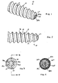
- FIG.1 is a perspective view of the suture anchor in accordance with the present invention.
- FIG. 2 is a side elevational view of the suture anchor shown in FIG. 1.
- FIG. 3 is a view of the proximal end of the suture anchor of the present invention.
- FIG. 4 is a view of the distal end of the suture anchor of the present invention.
- FIG. 5 is a cross-sectional view of the suture anchor through the plane V-V in FIG. 3.
- FIG. 6 is a cross-sectional view of the suture anchor through the plane VI-VI in FIG. 5.
- FIGS. 7 and 8 are side elevational views of a driver used in connection with the suture anchor of the present invention.
- Suture anchor 10 includes a body 12 formed generally in the shape of a slightly tapered cylinder and having a blunt or slightly rounded distal end.
- suture anchor 10 is provided with about eight flights of thread 14 wrapping around body 12, with the angle of the proximal surface 16 of each thread being approximately between one-third and one-fourth the angle of the distal surface 18 of each thread relative to the horizontal.
- the proximal surface of each thread has an angle of 12° relative to a plane horizontal to the axis of the suture anchor, while the distal surface of each thread has an angle of 45° relative to the same horizontal plane.
- body 12 of suture anchor 10 has a length of about 0.6 in and an exterior diameter of about 0,22 in. (5.5 mm) as measured across the outer diameter of the threading at the proximal end of the anchor.
- suture anchor 10 is provided with a bore 22 starting from an opening 20 at the proximal end and extending into the anchor body 12 approximately two-thirds of the length therethrough.
- FIGS. 3-6 illustrate bore 22 having a hexagonal cross-section, and although references to the bore 22 will be made in this application as to the hexagonal bore 22, the invention is not limited to this embodiment and contemplates suture anchors provided with central bores having various cross-sectional configurations.
- anchor body 12 is solid except for four passageways (only 24c and 24d are seen in FIG. 6) extending to four corresponding apertures 26a-26d on the curved surface of the distal end of suture anchor 10.
- the four apertures 26a-26d are arranged in two pairs, i.e. 26a-26b and 26c-26d, with each pair defining the ends of a respective groove 30a, 30b formed at the distal end of suture anchor 10.
- the two grooves 30a, 30b are parallel and recessed from a most distal surface 33 of suture anchor 10 so as to define a ridge 32 between them.
- Two strands of suture can be threaded into suture anchor 10, with the two ends of one suture strand being threaded through apertures 26a and 26b formed in groove 30a, and the two ends of another suture strand being threaded through apertures 26c and 26d in groove 30b.
- the ends of the suture strands are passed through the respective passageways 24a-24d and the hexagonal bore 22 to exit the suture anchor 10 from the proximal opening 20.
- the view from the distal end of suture anchor 10 is similar to that of a button sewed onto an article of clothing with thread.
- the portions of the sutures contacting the distal end surface of suture anchor lie in the grooves 30a, 30b between ridge 34 and the exterior walls of the grooves, and are protected from abrasion thereby.
- apertures 26a and 26c, and also 26b and 26d can be placed close together since they are not in the same groove; hence, there will be no force exerted on suture anchor body 12 between these respective apertures.
- the greater distance between apertures 26a and 26b, and also 26c and 26d at the ends of groove 30a and 30b, respectively, and the solid material of body 12 forming the regions between these pairs of apertures provide the structural integrity to support the stress exerted on the suture anchor 10 by the sutures threaded therethrough.
- the centers of the pair of apertures 26a, 26b and 26c, 26d formed in each groove 30a, 30b are spaced approximately 0.05 to about 0.08 in., more preferably approximately 0,065 in., apart, while the centers of adjacent apertures 26a, 26c and 26b, 26d from the opposing grooves are spaced much closer, e.g. approximately 0.032 in.
- the proximal surface and associated edges of suture anchor 10 defining the hexagonally shaped opening 20 is rounded and smooth.
- the proximal surface of the suture anchor 10 forming the periphery of the opening 20 forms a rounded lip 28 so that opening 20 has a slightly wider diameter than the main portion of hexagonal bore 22.
- Prior art anchors have sharp edges surrounding the drive opening, which are problematic in that any sutures passed through the central cannula of the anchor can be abraded by the sharp edges, thereby compromising the strength of the sutures. With the smooth and rounded proximal end provided in the anchor according to the present invention, sutures threaded through the apertures 26 will not become frayed upon pressure or rubbing against the anchor at the proximal opening.
- suture anchor body 12 can be provided with only two apertures 26 and one groove 30, or can be provided with more than two pairs of apertures and a corresponding number of grooves.
- suture anchor 10 is made from a bioabsorbable polymer material such as a polyglycolic or polylactic acid polymer poly(l-lactide-co-d, l-lactide) 70:30 (PLDLA) being most preferred.
- a bioabsorbable polymer material such as a polyglycolic or polylactic acid polymer poly(l-lactide-co-d, l-lactide) 70:30 (PLDLA) being most preferred.
- PLDLA polylactic acid polymer poly(l-lactide-co-d, l-lactide) 70:30
- the sutures used in connection with the inventive suture anchor are also bioabsorbable, such as No. 2 or No.5 USP braided polyester.
- the suture anchor can be made from other bioabsorbable materials known in the art.
- bioabsorbable is considered to be interchangeable with the term “biodegradable,” “resorbable,” and “absorbable” to mean that the device can be absorbed by the body over time.
- the measurements, angles and ratios between the dimensions of the suture anchor may be varied from those described above so as to be suitable for the conditions and applications in which the suture anchor is to be used,
- the suture anchor can be distributed with at least one strand of suture already threaded through the apertures 26a-26d.
- a driver such as that shown in FIGS. 7 and 8 is used to install the suture anchor 10 of the present invention during an arthroscopic procedure.
- Driver 50 has a handle 52, a shaft 54, and a drive head 56.
- Drive head 56 is hexagonally shaped and has a width and a length which substantially corresponds to the width and length of hexagonal bore 22 in suture anchor 10.
- the drive head is slightly shorter and has a slightly smaller width than bore 22, so that the fit is not too tight yet ensures secure engagement for driving the suture anchor into bone.
- Driver 50 is cannulated throughout the length thereof, with a distal opening at the distal face of drive head 56 and a proximal opening at the proximal surface of handle 52. Sutures threaded through suture anchor 10 from apertures 26a-26d at the distal end thereof and exiting through the proximal opening 20 can thus be passed through the cannula through driver 50 when drive head 56 is to be engaged with bore 22 in suture anchor 10 for driving the same.
- Handle 52 preferably includes an elongated double hook 52 extending substantially along the length thereof and having a hook at the proximal end and at the distal end thereof, and a clip 60 formed at one end region of the double hook 52.
- Driver 50 is preferably constructed to withstand an application of 20 in/lb of torque, Preferably, though not necessarily, at least the shaft 54 and drive head 56 are made of stainless steel. However, other materials may be used which provide the necessary strength and rigidity for installing the suture anchor of the present invention into cortical bone.
- a hole is pre-formed in the bone, either with a punch or a drill.
- the diameter of the hole formed is slightly ( e.g. 1 mm) smaller than the diameter of the suture anchor to be installed, to ensure good purchase of the suture anchor threads in the bone.
- the ends of the suture strands threaded through the suture anchor 10 are then threaded through the cannula in driver 50, and the distal end of the hexagonal drive head 56 of the driver is then inserted into the hexagonal bore 22 of the anchor 10 so that the shoulder 62 forming the transition between the drive head 56 and the drive shaft 54 abuts the lip 28 at the proximal surface of suture anchor 10. If necessary or applicable, excess lengths of the sutures exiting the proximal end of driver 50 are wrapped around the double hook 58 and/or clipped in clip 60.
- the suture anchor is then placed at the opening of the prepared hole in the bone, and the driver 50 is rotated until the proximal surface of the anchor is flush with the surface of the bone. Since it is not necessary for the proximal end of the anchor to be countersunk below the bone surface to prevent tissue abrasion, as is required with prior art devices, the inventive anchor does not need to be inserted as far as prior art devices, and avoids abrasion of the sutures by the rim of the bone around the installed suture anchor,
- the suture anchor of the present invention provides advantages in addition to those already discussed above. For example, with the threads provided along the entire length of the suture anchor body, the anchor is afforded maximum securement by the threads in the cortical bone, unlike some prior art anchors in which the threads only contact the cancellous bone. Also, the significant depth of the hexagonal bore for receiving the driver allows the suture anchor to be installed with a higher torque than many prior art anchors, thus imparting greater fixation strength to the installed anchor of the present invention.
Landscapes
- Health & Medical Sciences (AREA)
- Surgery (AREA)
- Life Sciences & Earth Sciences (AREA)
- Biomedical Technology (AREA)
- Nuclear Medicine, Radiotherapy & Molecular Imaging (AREA)
- Engineering & Computer Science (AREA)
- Rheumatology (AREA)
- Heart & Thoracic Surgery (AREA)
- Medical Informatics (AREA)
- Molecular Biology (AREA)
- Animal Behavior & Ethology (AREA)
- General Health & Medical Sciences (AREA)
- Public Health (AREA)
- Veterinary Medicine (AREA)
- Surgical Instruments (AREA)
Abstract
Description
- The present invention relates to an apparatus for anchoring surgical suture to bone. More specifically, the present invention relates to a suture anchor having apertures at the distal tip thereof for anchoring sutures in the cortical bone during arthroscopic surgery.
- When soft tissue tears away from bone, re-attachment becomes necessary. Various devices, including sutures, screws, staples, wedges, and plugs have been used in the prior art to secure soft tissue to bone.
- Recently, various types of threaded suture anchors have been developed for this purpose. Some threaded suture anchors are designed to be inserted into a pre-drilled hole. Other suture anchors are self-tapping.
- U.S. Patent No. 5,156,616, for example, discloses a suture anchor which has an axial passageway extending through the suture anchor. The passageway has a proximal portion, a central portion, and a distal portion. The proximal portion is hexagonally-shaped to cooperate with a hex driver for installing the anchor. The distal portion is sized to receive a knotted piece of suture, and the central portion has a diameter less than the that of the proximal and distal portions to receive the suture being threaded therethrough. Use of the suture anchor disclosed in the '616 patent, however, requires tying a suture knot. If the knot is not tied securely or if the knot is not made large enough, there is a risk that the knot will unravel or be pulled through the distal portion of the passageway,
- Another prior art suture anchor is disclosed in U.S. Patent No. 5,370,662 and has an eyelet located on the proximal end of the anchor through which a suture can be passed. Since the eyelet is formed as part of the drive head, however, combining these two functions in one structure often tends to weaken the drive head,
- Problems can arise if the structure for attaching the suture fails, allowing the suture to become detached from the anchor. For example, if the suture anchor is biodegradable, the eyelet can degrade rapidly, causing the suture to become detached from the anchor prematurely.
- Further, such a prior art suture anchor having an eyelet extending from the proximal end thereof requires countersinking of the eyelet below the bone surface to avoid having the patient's tissue abrade against the exposed eyelet. As a result, suture attached to the eyelet is vulnerable to abrasion by the bony rim of the countersunk hole into which the suture anchor is installed.
- In addition, various other modifications to the drive head often are employed in connection with suture attachment. For example, recessed grooves may be formed on opposite sides of the drive head to receive and protect the suture from abrasive areas of the suture anchor tunnel or to facilitate mating between the anchor to the driver. In such cases, the drive head often must be made of a larger diameter to recover the mechanical strength lost from the removal of material relating to the suture-attachment or suture-protection modifications.
- Accordingly, a need exists for a threaded suture anchor to which suture is secured effectively so as to prevent detachment of the suture. In addition, a need exists for suture anchors that will not abrade tissue and do not require countersinking.
- The present invention provides a suture anchor which securely affixes sutures to the anchor without subjecting the sutures to abrasion by the surrounding bone or subjecting the tissue to be secured with the suture anchor to be abraded by the sutures. Moreover, the suture anchor according to the present invention can be installed without countersinking.
- The suture anchor according to the present invention includes a threaded anchor body having a bore for receiving a driver, and preferably four distal passageways extending from the bore to four corresponding apertures at the distal end of the suture anchor. In this embodiment the apertures are provided as two pairs with a corresponding groove formed between the apertures of each pair.
- Suture strands can be inserted into the suture anchor through the apertures, and when the ends of the sutures are pulled as far as possible out the proximal end of the suture anchor, the portion of the sutures seated in the grooves are thereby protected from abrasion during installation of the suture anchor.
- Other features and advantages of the present invention will become apparent from the following description of the invention, which refers to the accompanying drawings.
- FIG.1 is a perspective view of the suture anchor in accordance with the present invention.
- FIG. 2 is a side elevational view of the suture anchor shown in FIG. 1.
- FIG. 3 is a view of the proximal end of the suture anchor of the present invention.
- FIG. 4 is a view of the distal end of the suture anchor of the present invention.
- FIG. 5 is a cross-sectional view of the suture anchor through the plane V-V in FIG. 3.
- FIG. 6 is a cross-sectional view of the suture anchor through the plane VI-VI in FIG. 5.
- FIGS. 7 and 8 are side elevational views of a driver used in connection with the suture anchor of the present invention.
- In the following detailed description, reference is made to various specific embodiments in which the invention may be practiced. These embodiments are described with sufficient detail to enable those skilled in the art to practice the invention, and it is to be understood that other embodiments may be employed, and that structural and logical changes may be made without departing from the spirit or scope of the present invention.
- Referring first to FIGS. 1 and 2, an exemplary embodiment of the suture anchor according to the present invention is identified generally by
reference numeral 10.Suture anchor 10 includes a body 12 formed generally in the shape of a slightly tapered cylinder and having a blunt or slightly rounded distal end. In an exemplary embodiment,suture anchor 10 is provided with about eight flights of thread 14 wrapping around body 12, with the angle of the proximal surface 16 of each thread being approximately between one-third and one-fourth the angle of the distal surface 18 of each thread relative to the horizontal. For example, in the preferred embodiment, the proximal surface of each thread has an angle of 12° relative to a plane horizontal to the axis of the suture anchor, while the distal surface of each thread has an angle of 45° relative to the same horizontal plane. - In an exemplary embodiment, body 12 of
suture anchor 10 has a length of about 0.6 in and an exterior diameter of about 0,22 in. (5.5 mm) as measured across the outer diameter of the threading at the proximal end of the anchor. - Referring now to FIGS. 3-6,
suture anchor 10 is provided with abore 22 starting from an opening 20 at the proximal end and extending into the anchor body 12 approximately two-thirds of the length therethrough. Although FIGS. 3-6 illustrate bore 22 having a hexagonal cross-section, and although references to thebore 22 will be made in this application as to thehexagonal bore 22, the invention is not limited to this embodiment and contemplates suture anchors provided with central bores having various cross-sectional configurations. Distally ofhexagonal bore 22, anchor body 12 is solid except for four passageways (only 24c and 24d are seen in FIG. 6) extending to four corresponding apertures 26a-26d on the curved surface of the distal end ofsuture anchor 10. - The four apertures 26a-26d are arranged in two pairs, i.e. 26a-26b and 26c-26d, with each pair defining the ends of a
respective groove suture anchor 10. The twogrooves suture anchor 10 so as to define aridge 32 between them. - Two strands of suture can be threaded into
suture anchor 10, with the two ends of one suture strand being threaded throughapertures 26a and 26b formed ingroove 30a, and the two ends of another suture strand being threaded throughapertures groove 30b. The ends of the suture strands are passed through the respective passageways 24a-24d and thehexagonal bore 22 to exit thesuture anchor 10 from theproximal opening 20. - With sutures threaded through
suture anchor 10 as described above, the view from the distal end ofsuture anchor 10 is similar to that of a button sewed onto an article of clothing with thread. When the sutures ends are pulled as far as possible out the proximal end ofsuture anchor 10, the portions of the sutures contacting the distal end surface of suture anchor lie in thegrooves - The
apertures 26a and 26c, and also 26b and 26d can be placed close together since they are not in the same groove; hence, there will be no force exerted on suture anchor body 12 between these respective apertures. On the other hand, the greater distance betweenapertures 26a and 26b, and also 26c and 26d at the ends ofgroove suture anchor 10 by the sutures threaded therethrough. In the preferred embodiment, the centers of the pair ofapertures groove adjacent apertures - The proximal surface and associated edges of
suture anchor 10 defining the hexagonallyshaped opening 20 is rounded and smooth. Preferably, the proximal surface of thesuture anchor 10 forming the periphery of theopening 20 forms arounded lip 28 so that opening 20 has a slightly wider diameter than the main portion ofhexagonal bore 22. Prior art anchors have sharp edges surrounding the drive opening, which are problematic in that any sutures passed through the central cannula of the anchor can be abraded by the sharp edges, thereby compromising the strength of the sutures. With the smooth and rounded proximal end provided in the anchor according to the present invention, sutures threaded through the apertures 26 will not become frayed upon pressure or rubbing against the anchor at the proximal opening. - As an alternative embodiment of the present invention, suture anchor body 12 can be provided with only two apertures 26 and one groove 30, or can be provided with more than two pairs of apertures and a corresponding number of grooves.
- Preferably,
suture anchor 10 is made from a bioabsorbable polymer material such as a polyglycolic or polylactic acid polymer poly(l-lactide-co-d, l-lactide) 70:30 (PLDLA) being most preferred. Also, it is preferred that the sutures used in connection with the inventive suture anchor are also bioabsorbable, such as No. 2 or No.5 USP braided polyester. - Although PLDLA is the most preferred material for the suture anchor of the present invention, the suture anchor can be made from other bioabsorbable materials known in the art. As used herein, the term "bioabsorbable" is considered to be interchangeable with the term "biodegradable," "resorbable," and "absorbable" to mean that the device can be absorbed by the body over time. Also, the measurements, angles and ratios between the dimensions of the suture anchor may be varied from those described above so as to be suitable for the conditions and applications in which the suture anchor is to be used,
- Optionally, the suture anchor can be distributed with at least one strand of suture already threaded through the apertures 26a-26d.
- A driver such as that shown in FIGS. 7 and 8 is used to install the
suture anchor 10 of the present invention during an arthroscopic procedure.Driver 50 has ahandle 52, ashaft 54, and adrive head 56. Drivehead 56 is hexagonally shaped and has a width and a length which substantially corresponds to the width and length ofhexagonal bore 22 insuture anchor 10. Preferably, the drive head is slightly shorter and has a slightly smaller width than bore 22, so that the fit is not too tight yet ensures secure engagement for driving the suture anchor into bone. -
Driver 50 is cannulated throughout the length thereof, with a distal opening at the distal face ofdrive head 56 and a proximal opening at the proximal surface ofhandle 52. Sutures threaded throughsuture anchor 10 from apertures 26a-26d at the distal end thereof and exiting through theproximal opening 20 can thus be passed through the cannula throughdriver 50 whendrive head 56 is to be engaged withbore 22 insuture anchor 10 for driving the same. -
Handle 52 preferably includes an elongateddouble hook 52 extending substantially along the length thereof and having a hook at the proximal end and at the distal end thereof, and a clip 60 formed at one end region of thedouble hook 52. Whendriver 50 is engaged withsuture anchor 10, excess lengths of suture passed through the proximal end ofdriver 50 can be wrapped around thedouble hook 52, and the ends of the sutures can be secured in the clip 60. In this manner, the suture strands can be prevented from becoming tangled or otherwise interfering with the surgeon's work. -
Driver 50 is preferably constructed to withstand an application of 20 in/lb of torque, Preferably, though not necessarily, at least theshaft 54 and drivehead 56 are made of stainless steel. However, other materials may be used which provide the necessary strength and rigidity for installing the suture anchor of the present invention into cortical bone. - To install the suture anchor of the present invention, a hole is pre-formed in the bone, either with a punch or a drill. Preferably, the diameter of the hole formed is slightly (e.g. 1 mm) smaller than the diameter of the suture anchor to be installed, to ensure good purchase of the suture anchor threads in the bone.
- The ends of the suture strands threaded through the
suture anchor 10 are then threaded through the cannula indriver 50, and the distal end of thehexagonal drive head 56 of the driver is then inserted into the hexagonal bore 22 of theanchor 10 so that theshoulder 62 forming the transition between thedrive head 56 and thedrive shaft 54 abuts thelip 28 at the proximal surface ofsuture anchor 10. If necessary or applicable, excess lengths of the sutures exiting the proximal end ofdriver 50 are wrapped around thedouble hook 58 and/or clipped in clip 60. - The suture anchor is then placed at the opening of the prepared hole in the bone, and the
driver 50 is rotated until the proximal surface of the anchor is flush with the surface of the bone. Since it is not necessary for the proximal end of the anchor to be countersunk below the bone surface to prevent tissue abrasion, as is required with prior art devices, the inventive anchor does not need to be inserted as far as prior art devices, and avoids abrasion of the sutures by the rim of the bone around the installed suture anchor, - The suture anchor of the present invention provides advantages in addition to those already discussed above. For example, with the threads provided along the entire length of the suture anchor body, the anchor is afforded maximum securement by the threads in the cortical bone, unlike some prior art anchors in which the threads only contact the cancellous bone. Also, the significant depth of the hexagonal bore for receiving the driver allows the suture anchor to be installed with a higher torque than many prior art anchors, thus imparting greater fixation strength to the installed anchor of the present invention.
- Although the present invention has been described in relation to particular embodiments thereof, many other variations and modifications and other uses will become apparent to those skilled in the art. Therefore, the present invention is to be limited not by the specific disclosure herein, but only by the appended claims.
Claims (13)
- A suture anchor comprising:an anchor body having a proximal end and a distal end;a central bore extending from an opening at the proximal end of the anchor body through a portion of the length thereof; andat least two apertures located at the distal end of the anchor body and in communication with the central bore.
- The suture anchor according to claim 1, wherein the two apertures are connected to respective passageways that extend through the anchor body substantially parallel to a longitudinal axis of the anchor body.
- The suture anchor according to claim 1, wherein the two apertures are connected by a groove at the distal end of the anchor body.
- The suture anchor according to claim 3, further comprising at least one strand of suture passing through the groove at the distal end of the anchor body and through the two apertures.
- The suture anchor according to claim 1, wherein the suture anchor comprises four apertures.
- The suture anchor according to claim 1, wherein the anchor body is threaded.
- The suture anchor according to claim 1, wherein the central bore has a hexagonal cross-sectional shape.
- The suture anchor according to claim 1, wherein the central bore has a cross-sectional shape so as to accommodate a driver head for driving the suture anchor.
- A suture anchor assembly for attachment of tissue to bone, the suture anchor assembly comprising:a suture anchor comprising an anchor body having a distal end, a proximal end, a longitudinal axis, an outer surface and a central bore located at the proximal end;at least two suture apertures located at the distal end of the anchor body; andat least one suture strand attached to the suture anchor and passing slidingly through the at least two suture apertures.
- The suture anchor assembly of claim 9, wherein each of the two suture apertures is connected to a respective distal passage comprising a proximal passage end and a distal passage end, the proximal passage end being in communication with the central bore, and the distal passage end being in communication with an aperture located at a most distal surface of the anchor body.
- The suture anchor assembly of claim 10, wherein the aperture is connected to a groove at the distal end of the anchor body.
- The suture anchor assembly of claim 11, wherein the suture strand passes through the groove at the distal end of the anchor body.
- The suture anchor assembly of claim 10, wherein the anchor body comprises a plurality of thread flights extending from the outer surface of the anchor body.
Applications Claiming Priority (2)
| Application Number | Priority Date | Filing Date | Title |
|---|---|---|---|
| US55942604P | 2004-04-06 | 2004-04-06 | |
| US559426 | 2004-04-06 |
Publications (2)
| Publication Number | Publication Date |
|---|---|
| EP1584297A1 true EP1584297A1 (en) | 2005-10-12 |
| EP1584297B1 EP1584297B1 (en) | 2015-11-18 |
Family
ID=34911024
Family Applications (1)
| Application Number | Title | Priority Date | Filing Date |
|---|---|---|---|
| EP05102678.9A Expired - Lifetime EP1584297B1 (en) | 2004-04-06 | 2005-04-05 | Suture anchor with apertures at tip |
Country Status (2)
| Country | Link |
|---|---|
| US (2) | US8579940B2 (en) |
| EP (1) | EP1584297B1 (en) |
Cited By (5)
| Publication number | Priority date | Publication date | Assignee | Title |
|---|---|---|---|---|
| FR2902635A1 (en) * | 2006-06-22 | 2007-12-28 | T H T Textile Hi Tec Sa | WELDING ANCHOR ELEMENT |
| US8771315B2 (en) | 2008-12-15 | 2014-07-08 | Smith & Nephew, Inc. | Composite anchor |
| CN105496530A (en) * | 2016-01-28 | 2016-04-20 | 苏州瑞华医院有限公司 | Lobulated hollow forcing screw |
| WO2017138917A1 (en) * | 2016-02-08 | 2017-08-17 | Crossroads Extremity Systems, Llc | Plantar plate repair |
| US10188378B2 (en) | 2013-03-06 | 2019-01-29 | Smith & Nephew, Inc. | Microanchor |
Families Citing this family (134)
| Publication number | Priority date | Publication date | Assignee | Title |
|---|---|---|---|---|
| US6610067B2 (en) | 2000-05-01 | 2003-08-26 | Arthrosurface, Incorporated | System and method for joint resurface repair |
| US8177841B2 (en) | 2000-05-01 | 2012-05-15 | Arthrosurface Inc. | System and method for joint resurface repair |
| EP2314257B9 (en) | 2000-05-01 | 2013-02-27 | ArthroSurface, Inc. | System for joint resurface repair |
| GB0208667D0 (en) | 2002-04-16 | 2002-05-29 | Atlantech Medical Devices Ltd | A transverse suspension device |
| US7914545B2 (en) | 2002-12-03 | 2011-03-29 | Arthrosurface, Inc | System and method for retrograde procedure |
| US8388624B2 (en) | 2003-02-24 | 2013-03-05 | Arthrosurface Incorporated | Trochlear resurfacing system and method |
| US8016865B2 (en) | 2003-09-29 | 2011-09-13 | Depuy Mitek, Inc. | Method of performing anterior cruciate ligament reconstruction using biodegradable interference screw |
| WO2005051231A2 (en) | 2003-11-20 | 2005-06-09 | Arthrosurface, Inc. | Retrograde delivery of resurfacing devices |
| WO2005069924A2 (en) | 2004-01-16 | 2005-08-04 | Arthrocare Corporation | Bone harvesting device and method |
| US7608092B1 (en) | 2004-02-20 | 2009-10-27 | Biomet Sports Medicince, LLC | Method and apparatus for performing meniscus repair |
| US8109965B2 (en) | 2004-06-09 | 2012-02-07 | Biomet Sports Medicine, LLP | Method and apparatus for soft tissue fixation |
| US7695503B1 (en) | 2004-06-09 | 2010-04-13 | Biomet Sports Medicine, Llc | Method and apparatus for soft tissue attachment |
| US7500983B1 (en) | 2004-06-09 | 2009-03-10 | Biomet Sports Medicine, Llc | Apparatus for soft tissue attachment |
| US7819898B2 (en) | 2004-06-09 | 2010-10-26 | Biomet Sports Medicine, Llc | Method and apparatus for soft tissue fixation |
| JP2008504107A (en) | 2004-06-28 | 2008-02-14 | アースロサーフィス・インコーポレーテッド | Joint surface replacement system |
| US7909851B2 (en) | 2006-02-03 | 2011-03-22 | Biomet Sports Medicine, Llc | Soft tissue repair device and associated methods |
| US7857830B2 (en) | 2006-02-03 | 2010-12-28 | Biomet Sports Medicine, Llc | Soft tissue repair and conduit device |
| US9017381B2 (en) | 2007-04-10 | 2015-04-28 | Biomet Sports Medicine, Llc | Adjustable knotless loops |
| US8298262B2 (en) | 2006-02-03 | 2012-10-30 | Biomet Sports Medicine, Llc | Method for tissue fixation |
| US9801708B2 (en) | 2004-11-05 | 2017-10-31 | Biomet Sports Medicine, Llc | Method and apparatus for coupling soft tissue to a bone |
| US20060189993A1 (en) | 2004-11-09 | 2006-08-24 | Arthrotek, Inc. | Soft tissue conduit device |
| US7905904B2 (en) | 2006-02-03 | 2011-03-15 | Biomet Sports Medicine, Llc | Soft tissue repair device and associated methods |
| US7601165B2 (en) | 2006-09-29 | 2009-10-13 | Biomet Sports Medicine, Llc | Method and apparatus for forming a self-locking adjustable suture loop |
| US8118836B2 (en) | 2004-11-05 | 2012-02-21 | Biomet Sports Medicine, Llc | Method and apparatus for coupling soft tissue to a bone |
| US8361113B2 (en) | 2006-02-03 | 2013-01-29 | Biomet Sports Medicine, Llc | Method and apparatus for coupling soft tissue to a bone |
| US8088130B2 (en) | 2006-02-03 | 2012-01-03 | Biomet Sports Medicine, Llc | Method and apparatus for coupling soft tissue to a bone |
| US8840645B2 (en) | 2004-11-05 | 2014-09-23 | Biomet Sports Medicine, Llc | Method and apparatus for coupling soft tissue to a bone |
| US8303604B2 (en) | 2004-11-05 | 2012-11-06 | Biomet Sports Medicine, Llc | Soft tissue repair device and method |
| US7905903B2 (en) | 2006-02-03 | 2011-03-15 | Biomet Sports Medicine, Llc | Method for tissue fixation |
| US8137382B2 (en) | 2004-11-05 | 2012-03-20 | Biomet Sports Medicine, Llc | Method and apparatus for coupling anatomical features |
| US7749250B2 (en) | 2006-02-03 | 2010-07-06 | Biomet Sports Medicine, Llc | Soft tissue repair assembly and associated method |
| US8128658B2 (en) | 2004-11-05 | 2012-03-06 | Biomet Sports Medicine, Llc | Method and apparatus for coupling soft tissue to bone |
| US8998949B2 (en) | 2004-11-09 | 2015-04-07 | Biomet Sports Medicine, Llc | Soft tissue conduit device |
| US7828853B2 (en) | 2004-11-22 | 2010-11-09 | Arthrosurface, Inc. | Articular surface implant and delivery system |
| US7591850B2 (en) | 2005-04-01 | 2009-09-22 | Arthrocare Corporation | Surgical methods for anchoring and implanting tissues |
| US7842042B2 (en) | 2005-05-16 | 2010-11-30 | Arthrocare Corporation | Convergent tunnel guide apparatus and method |
| GB0524360D0 (en) * | 2005-11-30 | 2006-01-04 | Biocomposites Ltd | Suture anchor |
| US9149267B2 (en) | 2006-02-03 | 2015-10-06 | Biomet Sports Medicine, Llc | Method and apparatus for coupling soft tissue to a bone |
| US8771352B2 (en) | 2011-05-17 | 2014-07-08 | Biomet Sports Medicine, Llc | Method and apparatus for tibial fixation of an ACL graft |
| US9538998B2 (en) | 2006-02-03 | 2017-01-10 | Biomet Sports Medicine, Llc | Method and apparatus for fracture fixation |
| US7959650B2 (en) | 2006-09-29 | 2011-06-14 | Biomet Sports Medicine, Llc | Adjustable knotless loops |
| US8652172B2 (en) | 2006-02-03 | 2014-02-18 | Biomet Sports Medicine, Llc | Flexible anchors for tissue fixation |
| US8562647B2 (en) | 2006-09-29 | 2013-10-22 | Biomet Sports Medicine, Llc | Method and apparatus for securing soft tissue to bone |
| US11311287B2 (en) | 2006-02-03 | 2022-04-26 | Biomet Sports Medicine, Llc | Method for tissue fixation |
| US8597327B2 (en) | 2006-02-03 | 2013-12-03 | Biomet Manufacturing, Llc | Method and apparatus for sternal closure |
| US8251998B2 (en) | 2006-08-16 | 2012-08-28 | Biomet Sports Medicine, Llc | Chondral defect repair |
| US11259792B2 (en) | 2006-02-03 | 2022-03-01 | Biomet Sports Medicine, Llc | Method and apparatus for coupling anatomical features |
| US10517587B2 (en) | 2006-02-03 | 2019-12-31 | Biomet Sports Medicine, Llc | Method and apparatus for forming a self-locking adjustable loop |
| US9078644B2 (en) | 2006-09-29 | 2015-07-14 | Biomet Sports Medicine, Llc | Fracture fixation device |
| US9468433B2 (en) | 2006-02-03 | 2016-10-18 | Biomet Sports Medicine, Llc | Method and apparatus for forming a self-locking adjustable loop |
| US8968364B2 (en) | 2006-02-03 | 2015-03-03 | Biomet Sports Medicine, Llc | Method and apparatus for fixation of an ACL graft |
| US8652171B2 (en) | 2006-02-03 | 2014-02-18 | Biomet Sports Medicine, Llc | Method and apparatus for soft tissue fixation |
| US8801783B2 (en) | 2006-09-29 | 2014-08-12 | Biomet Sports Medicine, Llc | Prosthetic ligament system for knee joint |
| US8562645B2 (en) | 2006-09-29 | 2013-10-22 | Biomet Sports Medicine, Llc | Method and apparatus for forming a self-locking adjustable loop |
| US8506597B2 (en) | 2011-10-25 | 2013-08-13 | Biomet Sports Medicine, Llc | Method and apparatus for interosseous membrane reconstruction |
| US8574235B2 (en) | 2006-02-03 | 2013-11-05 | Biomet Sports Medicine, Llc | Method for trochanteric reattachment |
| US9271713B2 (en) | 2006-02-03 | 2016-03-01 | Biomet Sports Medicine, Llc | Method and apparatus for tensioning a suture |
| US7828820B2 (en) | 2006-03-21 | 2010-11-09 | Biomet Sports Medicine, Llc | Method and apparatuses for securing suture |
| US9918826B2 (en) | 2006-09-29 | 2018-03-20 | Biomet Sports Medicine, Llc | Scaffold for spring ligament repair |
| US11259794B2 (en) | 2006-09-29 | 2022-03-01 | Biomet Sports Medicine, Llc | Method for implanting soft tissue |
| US8500818B2 (en) | 2006-09-29 | 2013-08-06 | Biomet Manufacturing, Llc | Knee prosthesis assembly with ligament link |
| US8672969B2 (en) | 2006-09-29 | 2014-03-18 | Biomet Sports Medicine, Llc | Fracture fixation device |
| US8083769B2 (en) | 2006-11-01 | 2011-12-27 | Depuy Mitek, Inc. | Wired sutures |
| US7686838B2 (en) | 2006-11-09 | 2010-03-30 | Arthrocare Corporation | External bullet anchor apparatus and method for use in surgical repair of ligament or tendon |
| AU2007332787A1 (en) | 2006-12-11 | 2008-06-19 | Arthrosurface Incorporated | Retrograde resection apparatus and method |
| US20080167660A1 (en) * | 2007-01-04 | 2008-07-10 | Nathan Ryan Moreau | Suture anchor and inserter arrangement |
| US12502169B2 (en) | 2007-01-16 | 2025-12-23 | Biomet Sports Medicine, Llc | Soft tissue repair device and associated methods |
| US9549809B2 (en) * | 2007-04-21 | 2017-01-24 | Kyon Ag | ACL prosthesis and anchor therefor |
| EP1987784B1 (en) * | 2007-04-30 | 2011-12-14 | Stryker Trauma GmbH | Device for preparing a non-rotational-symmetric recess in a bone |
| US20090024174A1 (en) * | 2007-07-17 | 2009-01-22 | Stark John G | Bone screws and particular applications to sacroiliac joint fusion |
| US8702754B2 (en) | 2007-09-14 | 2014-04-22 | Depuy Mitek, Llc | Methods for anchoring suture to bone |
| US8882801B2 (en) | 2007-09-14 | 2014-11-11 | Depuy Mitek, Llc | Dual thread cannulated suture anchor |
| US8197511B2 (en) | 2007-09-24 | 2012-06-12 | Miller M Todd | Suture anchor having a suture engaging structure and inserter arrangement |
| US8632568B2 (en) | 2007-09-24 | 2014-01-21 | Stryker Corporation | Suture anchor having a suture engaging structure and inserter arrangement |
| WO2009111481A1 (en) | 2008-03-03 | 2009-09-11 | Arthrosurface Incorporated | Bone resurfacing system and method |
| US8974505B2 (en) * | 2008-06-16 | 2015-03-10 | Anna G. U. Sawa | Venting/pressure adjustment to aid in delivery of material into an anatomic region via a cannula |
| US12245759B2 (en) | 2008-08-22 | 2025-03-11 | Biomet Sports Medicine, Llc | Method and apparatus for coupling soft tissue to bone |
| US12419632B2 (en) | 2008-08-22 | 2025-09-23 | Biomet Sports Medicine, Llc | Method and apparatus for coupling anatomical features |
| US10945743B2 (en) | 2009-04-17 | 2021-03-16 | Arthrosurface Incorporated | Glenoid repair system and methods of use thereof |
| CA3064646C (en) | 2009-04-17 | 2023-01-03 | Arthrosurface Incorporated | Glenoid resurfacing system and method |
| WO2010121250A1 (en) | 2009-04-17 | 2010-10-21 | Arthrosurface Incorporated | Glenoid resurfacing system and method |
| US8343227B2 (en) | 2009-05-28 | 2013-01-01 | Biomet Manufacturing Corp. | Knee prosthesis assembly with ligament link |
| US12096928B2 (en) | 2009-05-29 | 2024-09-24 | Biomet Sports Medicine, Llc | Method and apparatus for coupling soft tissue to a bone |
| US12551209B2 (en) | 2009-06-22 | 2026-02-17 | Biomet Sports Medicine, Llc | Method and apparatus for coupling soft tissue to a bone |
| US12616462B2 (en) | 2009-09-30 | 2026-05-05 | Biomet Sports Medicine, Llc | Soft tissue repair device and method |
| US9393006B2 (en) | 2009-10-28 | 2016-07-19 | Smith & Nephew, Inc. | Threaded suture anchor |
| US8672967B2 (en) * | 2009-10-30 | 2014-03-18 | Depuy Mitek, Llc | Partial thickness rotator cuff repair system and method |
| US8449612B2 (en) | 2009-11-16 | 2013-05-28 | Arthrocare Corporation | Graft pulley and methods of use |
| FR2960763B1 (en) * | 2010-06-03 | 2013-08-02 | Tornier Sa | SUTURE IMPLANT |
| BR112012022482A2 (en) | 2010-03-05 | 2016-07-19 | Arthrosurface Inc | tibial surface recomposition system and method. |
| US9775702B2 (en) * | 2010-03-10 | 2017-10-03 | Smith & Nephew, Inc. | Composite interference screws and drivers |
| KR101917895B1 (en) | 2010-09-24 | 2018-11-12 | 스포트벨딩 게엠베하 | Suture anchor and method for fixating a suture relative to hard tissue |
| RU2700362C2 (en) | 2010-09-24 | 2019-09-16 | СпортУэлдинг ГмбХ | Surgical suture retainer |
| PL2618747T3 (en) | 2010-09-24 | 2015-03-31 | Sportwelding Gmbh | Device for fixating a suture anchor in hard tissue |
| EP3632341B1 (en) | 2011-01-28 | 2022-11-09 | Sportwelding GmbH | Device for fixating a suture anchor with a suture or a headed anchor in hard tissue |
| CN106806004B (en) | 2011-01-28 | 2019-08-23 | 斯博特威尔丁股份有限公司 | For that will have the suture anchor of suture or there is an anchor to be fixed to the device and method in sclerous tissues |
| US9066716B2 (en) | 2011-03-30 | 2015-06-30 | Arthrosurface Incorporated | Suture coil and suture sheath for tissue repair |
| US12329373B2 (en) | 2011-05-02 | 2025-06-17 | Biomet Sports Medicine, Llc | Method and apparatus for soft tissue fixation |
| US9357991B2 (en) | 2011-11-03 | 2016-06-07 | Biomet Sports Medicine, Llc | Method and apparatus for stitching tendons |
| US12582395B2 (en) | 2011-11-03 | 2026-03-24 | Biomet Sports Medicine, Llc | Method and apparatus for forming a self-locking adjustable loop |
| US9370350B2 (en) | 2011-11-10 | 2016-06-21 | Biomet Sports Medicine, Llc | Apparatus for coupling soft tissue to a bone |
| US9357992B2 (en) | 2011-11-10 | 2016-06-07 | Biomet Sports Medicine, Llc | Method for coupling soft tissue to a bone |
| US9381013B2 (en) | 2011-11-10 | 2016-07-05 | Biomet Sports Medicine, Llc | Method for coupling soft tissue to a bone |
| EP2804565B1 (en) | 2011-12-22 | 2018-03-07 | Arthrosurface Incorporated | System for bone fixation |
| US9259217B2 (en) | 2012-01-03 | 2016-02-16 | Biomet Manufacturing, Llc | Suture Button |
| US8858596B2 (en) | 2012-03-20 | 2014-10-14 | Stryker Corporation | Suture anchor having a suture engaging structure |
| DE112013003358T5 (en) | 2012-07-03 | 2015-03-19 | Arthrosurface, Inc. | System and procedure for joint surface replacement and repair |
| US9757119B2 (en) | 2013-03-08 | 2017-09-12 | Biomet Sports Medicine, Llc | Visual aid for identifying suture limbs arthroscopically |
| AU2014249201B2 (en) * | 2013-03-12 | 2018-08-02 | Ziptek LLC. | Apparatus and method for securing tissue |
| US9918827B2 (en) | 2013-03-14 | 2018-03-20 | Biomet Sports Medicine, Llc | Scaffold for spring ligament repair |
| US9492200B2 (en) | 2013-04-16 | 2016-11-15 | Arthrosurface Incorporated | Suture system and method |
| US10136886B2 (en) | 2013-12-20 | 2018-11-27 | Biomet Sports Medicine, Llc | Knotless soft tissue devices and techniques |
| US10624748B2 (en) | 2014-03-07 | 2020-04-21 | Arthrosurface Incorporated | System and method for repairing articular surfaces |
| US9931219B2 (en) | 2014-03-07 | 2018-04-03 | Arthrosurface Incorporated | Implant and anchor assembly |
| US11607319B2 (en) | 2014-03-07 | 2023-03-21 | Arthrosurface Incorporated | System and method for repairing articular surfaces |
| US9615822B2 (en) | 2014-05-30 | 2017-04-11 | Biomet Sports Medicine, Llc | Insertion tools and method for soft anchor |
| US9700291B2 (en) | 2014-06-03 | 2017-07-11 | Biomet Sports Medicine, Llc | Capsule retractor |
| USD740417S1 (en) * | 2014-08-08 | 2015-10-06 | Dunamis, LLC | Suture anchor |
| USD740418S1 (en) * | 2014-08-08 | 2015-10-06 | Dunamis, LLC | Suture anchor |
| USD741480S1 (en) * | 2014-08-08 | 2015-10-20 | Dunamis, LLC | Suture anchor |
| USD740419S1 (en) * | 2014-08-08 | 2015-10-06 | Dunamis, LLC | Suture anchor |
| US10039543B2 (en) | 2014-08-22 | 2018-08-07 | Biomet Sports Medicine, Llc | Non-sliding soft anchor |
| US10022115B2 (en) * | 2014-10-29 | 2018-07-17 | Valeris Medical, Llc | Two suture anchor |
| US9955980B2 (en) | 2015-02-24 | 2018-05-01 | Biomet Sports Medicine, Llc | Anatomic soft tissue repair |
| US9974534B2 (en) | 2015-03-31 | 2018-05-22 | Biomet Sports Medicine, Llc | Suture anchor with soft anchor of electrospun fibers |
| US10188379B2 (en) * | 2015-09-03 | 2019-01-29 | Ethicon Llc | End effector for wound closure device |
| WO2017075095A1 (en) * | 2015-10-26 | 2017-05-04 | Popovitz Leon | Circulation replenishing joint implant |
| US10383618B2 (en) * | 2017-03-13 | 2019-08-20 | Medos International Sarl | Methods and devices for knotless suture anchoring |
| CA3108761A1 (en) | 2017-08-04 | 2019-02-07 | Arthrosurface Incorporated | Multicomponent articular surface implant |
| CN107569265A (en) * | 2017-10-18 | 2018-01-12 | 运怡(北京)医疗器械有限公司 | A screw-in anchor with wire |
| US11266492B2 (en) * | 2019-02-02 | 2022-03-08 | Daniel M Hoopes | Tension to compression tendon fixation |
| GB2609338B (en) | 2019-03-12 | 2023-06-14 | Arthrosurface Inc | Humeral and glenoid articular surface implant systems and methods |
| USD909858S1 (en) * | 2019-06-19 | 2021-02-09 | Chang gi Im | Bolt |
| US12133644B2 (en) | 2021-02-19 | 2024-11-05 | Medos International Sarl | Knotless instability devices and methods for soft tissue repair |
Citations (5)
| Publication number | Priority date | Publication date | Assignee | Title |
|---|---|---|---|---|
| US5156616A (en) | 1992-02-10 | 1992-10-20 | Meadows Bruce F | Apparatus and method for suture attachment |
| US5306290A (en) | 1993-02-12 | 1994-04-26 | Mitek Surgical Products, Inc. | Suture button |
| US5571139A (en) | 1995-05-19 | 1996-11-05 | Jenkins, Jr.; Joseph R. | Bidirectional suture anchor |
| US5885294A (en) | 1997-09-22 | 1999-03-23 | Ethicon, Inc. | Apparatus and method for anchoring a cord-like element to a workpiece |
| US20030065361A1 (en) | 2001-10-02 | 2003-04-03 | Dreyfuss Peter J. | Suture anchor with internal suture loop |
Family Cites Families (4)
| Publication number | Priority date | Publication date | Assignee | Title |
|---|---|---|---|---|
| US1610309A (en) * | 1926-01-04 | 1926-12-14 | Niederer Otto | Button |
| US5480403A (en) * | 1991-03-22 | 1996-01-02 | United States Surgical Corporation | Suture anchoring device and method |
| US5370662A (en) | 1993-06-23 | 1994-12-06 | Kevin R. Stone | Suture anchor assembly |
| US6436124B1 (en) * | 1996-12-19 | 2002-08-20 | Bionx Implants Oy | Suture anchor |
-
2005
- 2005-04-04 US US11/097,180 patent/US8579940B2/en active Active
- 2005-04-05 EP EP05102678.9A patent/EP1584297B1/en not_active Expired - Lifetime
-
2013
- 2013-11-11 US US14/077,012 patent/US20140074164A1/en not_active Abandoned
Patent Citations (5)
| Publication number | Priority date | Publication date | Assignee | Title |
|---|---|---|---|---|
| US5156616A (en) | 1992-02-10 | 1992-10-20 | Meadows Bruce F | Apparatus and method for suture attachment |
| US5306290A (en) | 1993-02-12 | 1994-04-26 | Mitek Surgical Products, Inc. | Suture button |
| US5571139A (en) | 1995-05-19 | 1996-11-05 | Jenkins, Jr.; Joseph R. | Bidirectional suture anchor |
| US5885294A (en) | 1997-09-22 | 1999-03-23 | Ethicon, Inc. | Apparatus and method for anchoring a cord-like element to a workpiece |
| US20030065361A1 (en) | 2001-10-02 | 2003-04-03 | Dreyfuss Peter J. | Suture anchor with internal suture loop |
Cited By (8)
| Publication number | Priority date | Publication date | Assignee | Title |
|---|---|---|---|---|
| FR2902635A1 (en) * | 2006-06-22 | 2007-12-28 | T H T Textile Hi Tec Sa | WELDING ANCHOR ELEMENT |
| EP1870041A3 (en) * | 2006-06-22 | 2009-07-29 | Textile Hi-Tec (T.H.T.) | Element for anchoring suture thread |
| US8771315B2 (en) | 2008-12-15 | 2014-07-08 | Smith & Nephew, Inc. | Composite anchor |
| US9386977B2 (en) | 2008-12-15 | 2016-07-12 | Smith & Nephew, Inc. | Composite anchor |
| US10188378B2 (en) | 2013-03-06 | 2019-01-29 | Smith & Nephew, Inc. | Microanchor |
| CN105496530A (en) * | 2016-01-28 | 2016-04-20 | 苏州瑞华医院有限公司 | Lobulated hollow forcing screw |
| WO2017138917A1 (en) * | 2016-02-08 | 2017-08-17 | Crossroads Extremity Systems, Llc | Plantar plate repair |
| US10799250B2 (en) | 2016-02-08 | 2020-10-13 | Crossroads Extremity Systems, Llc | Plantar plate repair |
Also Published As
| Publication number | Publication date |
|---|---|
| US8579940B2 (en) | 2013-11-12 |
| EP1584297B1 (en) | 2015-11-18 |
| US20050222619A1 (en) | 2005-10-06 |
| US20140074164A1 (en) | 2014-03-13 |
Similar Documents
| Publication | Publication Date | Title |
|---|---|---|
| EP1584297B1 (en) | Suture anchor with apertures at tip | |
| US12064104B2 (en) | Fully-threaded bioabsorbable suture anchor | |
| EP0916312B1 (en) | Suture anchor with insert-molded suture | |
| US8343186B2 (en) | Fully threaded suture anchor with transverse anchor pin | |
| EP1917915B1 (en) | Suture anchor with pulley | |
| US6652563B2 (en) | Suture anchor with internal suture loop | |
| EP1762186B1 (en) | Suture anchor with eyelet | |
| CA2962989C (en) | Dual thread cannulated suture anchor | |
| US20040039404A1 (en) | Suture anchor attached to tissue-fixation disk without top knot | |
| US20020052629A1 (en) | Apparatus and method for securing suture to bone | |
| EP1797828B1 (en) | Threaded suture anchor with starting pitch |
Legal Events
| Date | Code | Title | Description |
|---|---|---|---|
| PUAI | Public reference made under article 153(3) epc to a published international application that has entered the european phase |
Free format text: ORIGINAL CODE: 0009012 |
|
| AK | Designated contracting states |
Kind code of ref document: A1 Designated state(s): AT BE BG CH CY CZ DE DK EE ES FI FR GB GR HU IE IS IT LI LT LU MC NL PL PT RO SE SI SK TR |
|
| AX | Request for extension of the european patent |
Extension state: AL BA HR LV MK YU |
|
| 17P | Request for examination filed |
Effective date: 20060410 |
|
| AKX | Designation fees paid |
Designated state(s): AT BE BG CH CY CZ DE DK EE ES FI FR GB GR HU IE IS IT LI LT LU MC NL PL PT RO SE SI SK TR |
|
| 17Q | First examination report despatched |
Effective date: 20110421 |
|
| GRAP | Despatch of communication of intention to grant a patent |
Free format text: ORIGINAL CODE: EPIDOSNIGR1 |
|
| INTG | Intention to grant announced |
Effective date: 20150610 |
|
| GRAS | Grant fee paid |
Free format text: ORIGINAL CODE: EPIDOSNIGR3 |
|
| GRAA | (expected) grant |
Free format text: ORIGINAL CODE: 0009210 |
|
| AK | Designated contracting states |
Kind code of ref document: B1 Designated state(s): AT BE BG CH CY CZ DE DK EE ES FI FR GB GR HU IE IS IT LI LT LU MC NL PL PT RO SE SI SK TR |
|
| REG | Reference to a national code |
Ref country code: GB Ref legal event code: FG4D |
|
| REG | Reference to a national code |
Ref country code: CH Ref legal event code: EP |
|
| REG | Reference to a national code |
Ref country code: AT Ref legal event code: REF Ref document number: 761113 Country of ref document: AT Kind code of ref document: T Effective date: 20151215 |
|
| REG | Reference to a national code |
Ref country code: IE Ref legal event code: FG4D |
|
| REG | Reference to a national code |
Ref country code: DE Ref legal event code: R096 Ref document number: 602005047931 Country of ref document: DE |
|
| REG | Reference to a national code |
Ref country code: NL Ref legal event code: MP Effective date: 20160218 |
|
| REG | Reference to a national code |
Ref country code: LT Ref legal event code: MG4D |
|
| REG | Reference to a national code |
Ref country code: FR Ref legal event code: PLFP Year of fee payment: 12 |
|
| REG | Reference to a national code |
Ref country code: AT Ref legal event code: MK05 Ref document number: 761113 Country of ref document: AT Kind code of ref document: T Effective date: 20151118 |
|
| PG25 | Lapsed in a contracting state [announced via postgrant information from national office to epo] |
Ref country code: IS Free format text: LAPSE BECAUSE OF FAILURE TO SUBMIT A TRANSLATION OF THE DESCRIPTION OR TO PAY THE FEE WITHIN THE PRESCRIBED TIME-LIMIT Effective date: 20160318 Ref country code: IT Free format text: LAPSE BECAUSE OF FAILURE TO SUBMIT A TRANSLATION OF THE DESCRIPTION OR TO PAY THE FEE WITHIN THE PRESCRIBED TIME-LIMIT Effective date: 20151118 Ref country code: NL Free format text: LAPSE BECAUSE OF FAILURE TO SUBMIT A TRANSLATION OF THE DESCRIPTION OR TO PAY THE FEE WITHIN THE PRESCRIBED TIME-LIMIT Effective date: 20151118 Ref country code: ES Free format text: LAPSE BECAUSE OF FAILURE TO SUBMIT A TRANSLATION OF THE DESCRIPTION OR TO PAY THE FEE WITHIN THE PRESCRIBED TIME-LIMIT Effective date: 20151118 Ref country code: LT Free format text: LAPSE BECAUSE OF FAILURE TO SUBMIT A TRANSLATION OF THE DESCRIPTION OR TO PAY THE FEE WITHIN THE PRESCRIBED TIME-LIMIT Effective date: 20151118 |
|
| PG25 | Lapsed in a contracting state [announced via postgrant information from national office to epo] |
Ref country code: GR Free format text: LAPSE BECAUSE OF FAILURE TO SUBMIT A TRANSLATION OF THE DESCRIPTION OR TO PAY THE FEE WITHIN THE PRESCRIBED TIME-LIMIT Effective date: 20160219 Ref country code: PL Free format text: LAPSE BECAUSE OF FAILURE TO SUBMIT A TRANSLATION OF THE DESCRIPTION OR TO PAY THE FEE WITHIN THE PRESCRIBED TIME-LIMIT Effective date: 20151118 Ref country code: PT Free format text: LAPSE BECAUSE OF FAILURE TO SUBMIT A TRANSLATION OF THE DESCRIPTION OR TO PAY THE FEE WITHIN THE PRESCRIBED TIME-LIMIT Effective date: 20160318 Ref country code: AT Free format text: LAPSE BECAUSE OF FAILURE TO SUBMIT A TRANSLATION OF THE DESCRIPTION OR TO PAY THE FEE WITHIN THE PRESCRIBED TIME-LIMIT Effective date: 20151118 Ref country code: FI Free format text: LAPSE BECAUSE OF FAILURE TO SUBMIT A TRANSLATION OF THE DESCRIPTION OR TO PAY THE FEE WITHIN THE PRESCRIBED TIME-LIMIT Effective date: 20151118 Ref country code: SE Free format text: LAPSE BECAUSE OF FAILURE TO SUBMIT A TRANSLATION OF THE DESCRIPTION OR TO PAY THE FEE WITHIN THE PRESCRIBED TIME-LIMIT Effective date: 20151118 |
|
| PG25 | Lapsed in a contracting state [announced via postgrant information from national office to epo] |
Ref country code: CZ Free format text: LAPSE BECAUSE OF FAILURE TO SUBMIT A TRANSLATION OF THE DESCRIPTION OR TO PAY THE FEE WITHIN THE PRESCRIBED TIME-LIMIT Effective date: 20151118 |
|
| REG | Reference to a national code |
Ref country code: DE Ref legal event code: R097 Ref document number: 602005047931 Country of ref document: DE |
|
| PG25 | Lapsed in a contracting state [announced via postgrant information from national office to epo] |
Ref country code: SK Free format text: LAPSE BECAUSE OF FAILURE TO SUBMIT A TRANSLATION OF THE DESCRIPTION OR TO PAY THE FEE WITHIN THE PRESCRIBED TIME-LIMIT Effective date: 20151118 Ref country code: BE Free format text: LAPSE BECAUSE OF NON-PAYMENT OF DUE FEES Effective date: 20160430 Ref country code: RO Free format text: LAPSE BECAUSE OF FAILURE TO SUBMIT A TRANSLATION OF THE DESCRIPTION OR TO PAY THE FEE WITHIN THE PRESCRIBED TIME-LIMIT Effective date: 20151118 Ref country code: EE Free format text: LAPSE BECAUSE OF FAILURE TO SUBMIT A TRANSLATION OF THE DESCRIPTION OR TO PAY THE FEE WITHIN THE PRESCRIBED TIME-LIMIT Effective date: 20151118 Ref country code: DK Free format text: LAPSE BECAUSE OF FAILURE TO SUBMIT A TRANSLATION OF THE DESCRIPTION OR TO PAY THE FEE WITHIN THE PRESCRIBED TIME-LIMIT Effective date: 20151118 |
|
| PLBE | No opposition filed within time limit |
Free format text: ORIGINAL CODE: 0009261 |
|
| STAA | Information on the status of an ep patent application or granted ep patent |
Free format text: STATUS: NO OPPOSITION FILED WITHIN TIME LIMIT |
|
| 26N | No opposition filed |
Effective date: 20160819 |
|
| PG25 | Lapsed in a contracting state [announced via postgrant information from national office to epo] |
Ref country code: SI Free format text: LAPSE BECAUSE OF FAILURE TO SUBMIT A TRANSLATION OF THE DESCRIPTION OR TO PAY THE FEE WITHIN THE PRESCRIBED TIME-LIMIT Effective date: 20151118 |
|
| REG | Reference to a national code |
Ref country code: CH Ref legal event code: PL |
|
| PG25 | Lapsed in a contracting state [announced via postgrant information from national office to epo] |
Ref country code: BE Free format text: LAPSE BECAUSE OF FAILURE TO SUBMIT A TRANSLATION OF THE DESCRIPTION OR TO PAY THE FEE WITHIN THE PRESCRIBED TIME-LIMIT Effective date: 20151118 Ref country code: LU Free format text: LAPSE BECAUSE OF FAILURE TO SUBMIT A TRANSLATION OF THE DESCRIPTION OR TO PAY THE FEE WITHIN THE PRESCRIBED TIME-LIMIT Effective date: 20160405 |
|
| REG | Reference to a national code |
Ref country code: IE Ref legal event code: MM4A |
|
| PG25 | Lapsed in a contracting state [announced via postgrant information from national office to epo] |
Ref country code: CH Free format text: LAPSE BECAUSE OF NON-PAYMENT OF DUE FEES Effective date: 20160430 Ref country code: LI Free format text: LAPSE BECAUSE OF NON-PAYMENT OF DUE FEES Effective date: 20160430 |
|
| REG | Reference to a national code |
Ref country code: FR Ref legal event code: PLFP Year of fee payment: 13 |
|
| PG25 | Lapsed in a contracting state [announced via postgrant information from national office to epo] |
Ref country code: IE Free format text: LAPSE BECAUSE OF NON-PAYMENT OF DUE FEES Effective date: 20160405 |
|
| REG | Reference to a national code |
Ref country code: FR Ref legal event code: PLFP Year of fee payment: 14 |
|
| PG25 | Lapsed in a contracting state [announced via postgrant information from national office to epo] |
Ref country code: HU Free format text: LAPSE BECAUSE OF FAILURE TO SUBMIT A TRANSLATION OF THE DESCRIPTION OR TO PAY THE FEE WITHIN THE PRESCRIBED TIME-LIMIT; INVALID AB INITIO Effective date: 20050405 Ref country code: CY Free format text: LAPSE BECAUSE OF FAILURE TO SUBMIT A TRANSLATION OF THE DESCRIPTION OR TO PAY THE FEE WITHIN THE PRESCRIBED TIME-LIMIT Effective date: 20151118 |
|
| PG25 | Lapsed in a contracting state [announced via postgrant information from national office to epo] |
Ref country code: MC Free format text: LAPSE BECAUSE OF FAILURE TO SUBMIT A TRANSLATION OF THE DESCRIPTION OR TO PAY THE FEE WITHIN THE PRESCRIBED TIME-LIMIT Effective date: 20151118 Ref country code: TR Free format text: LAPSE BECAUSE OF FAILURE TO SUBMIT A TRANSLATION OF THE DESCRIPTION OR TO PAY THE FEE WITHIN THE PRESCRIBED TIME-LIMIT Effective date: 20151118 |
|
| PG25 | Lapsed in a contracting state [announced via postgrant information from national office to epo] |
Ref country code: BG Free format text: LAPSE BECAUSE OF FAILURE TO SUBMIT A TRANSLATION OF THE DESCRIPTION OR TO PAY THE FEE WITHIN THE PRESCRIBED TIME-LIMIT Effective date: 20151118 |
|
| PGFP | Annual fee paid to national office [announced via postgrant information from national office to epo] |
Ref country code: GB Payment date: 20240229 Year of fee payment: 20 |
|
| PGFP | Annual fee paid to national office [announced via postgrant information from national office to epo] |
Ref country code: FR Payment date: 20240308 Year of fee payment: 20 |
|
| PGFP | Annual fee paid to national office [announced via postgrant information from national office to epo] |
Ref country code: DE Payment date: 20240306 Year of fee payment: 20 |
|
| REG | Reference to a national code |
Ref country code: DE Ref legal event code: R071 Ref document number: 602005047931 Country of ref document: DE |
|
| REG | Reference to a national code |
Ref country code: GB Ref legal event code: PE20 Expiry date: 20250404 |
|
| PG25 | Lapsed in a contracting state [announced via postgrant information from national office to epo] |
Ref country code: GB Free format text: LAPSE BECAUSE OF EXPIRATION OF PROTECTION Effective date: 20250404 |