EP1583879B1 - Opening and closing latch device for furniture - Google Patents
Opening and closing latch device for furniture Download PDFInfo
- Publication number
- EP1583879B1 EP1583879B1 EP04791222A EP04791222A EP1583879B1 EP 1583879 B1 EP1583879 B1 EP 1583879B1 EP 04791222 A EP04791222 A EP 04791222A EP 04791222 A EP04791222 A EP 04791222A EP 1583879 B1 EP1583879 B1 EP 1583879B1
- Authority
- EP
- European Patent Office
- Prior art keywords
- latch device
- furniture
- container
- opening
- track
- Prior art date
- Legal status (The legal status is an assumption and is not a legal conclusion. Google has not performed a legal analysis and makes no representation as to the accuracy of the status listed.)
- Expired - Lifetime
Links
- 238000004519 manufacturing process Methods 0.000 description 2
- 230000006835 compression Effects 0.000 description 1
- 238000007906 compression Methods 0.000 description 1
- 230000001419 dependent effect Effects 0.000 description 1
- 230000005923 long-lasting effect Effects 0.000 description 1
- 238000000034 method Methods 0.000 description 1
- 238000000465 moulding Methods 0.000 description 1
- 230000000284 resting effect Effects 0.000 description 1
Images


Classifications
-
- E—FIXED CONSTRUCTIONS
- E05—LOCKS; KEYS; WINDOW OR DOOR FITTINGS; SAFES
- E05C—BOLTS OR FASTENING DEVICES FOR WINGS, SPECIALLY FOR DOORS OR WINDOWS
- E05C19/00—Other devices specially designed for securing wings, e.g. with suction cups
- E05C19/02—Automatic catches, i.e. released by pull or pressure on the wing
- E05C19/022—Released by pushing in the closing direction
-
- E—FIXED CONSTRUCTIONS
- E05—LOCKS; KEYS; WINDOW OR DOOR FITTINGS; SAFES
- E05B—LOCKS; ACCESSORIES THEREFOR; HANDCUFFS
- E05B65/00—Locks or fastenings for special use
- E05B65/46—Locks or fastenings for special use for drawers
-
- E—FIXED CONSTRUCTIONS
- E05—LOCKS; KEYS; WINDOW OR DOOR FITTINGS; SAFES
- E05B—LOCKS; ACCESSORIES THEREFOR; HANDCUFFS
- E05B17/00—Accessories in connection with locks
- E05B17/0025—Devices for forcing the wing firmly against its seat or to initiate the opening of the wing
- E05B17/0033—Devices for forcing the wing firmly against its seat or to initiate the opening of the wing for opening only
- E05B17/0037—Spring-operated
-
- Y—GENERAL TAGGING OF NEW TECHNOLOGICAL DEVELOPMENTS; GENERAL TAGGING OF CROSS-SECTIONAL TECHNOLOGIES SPANNING OVER SEVERAL SECTIONS OF THE IPC; TECHNICAL SUBJECTS COVERED BY FORMER USPC CROSS-REFERENCE ART COLLECTIONS [XRACs] AND DIGESTS
- Y10—TECHNICAL SUBJECTS COVERED BY FORMER USPC
- Y10T—TECHNICAL SUBJECTS COVERED BY FORMER US CLASSIFICATION
- Y10T292/00—Closure fasteners
- Y10T292/08—Bolts
- Y10T292/0911—Hooked end
- Y10T292/0926—Spring projected
- Y10T292/0928—Operating means
- Y10T292/093—Cam
-
- Y—GENERAL TAGGING OF NEW TECHNOLOGICAL DEVELOPMENTS; GENERAL TAGGING OF CROSS-SECTIONAL TECHNOLOGIES SPANNING OVER SEVERAL SECTIONS OF THE IPC; TECHNICAL SUBJECTS COVERED BY FORMER USPC CROSS-REFERENCE ART COLLECTIONS [XRACs] AND DIGESTS
- Y10—TECHNICAL SUBJECTS COVERED BY FORMER USPC
- Y10T—TECHNICAL SUBJECTS COVERED BY FORMER US CLASSIFICATION
- Y10T292/00—Closure fasteners
- Y10T292/08—Bolts
- Y10T292/0911—Hooked end
- Y10T292/0937—Gravity actuated
-
- Y—GENERAL TAGGING OF NEW TECHNOLOGICAL DEVELOPMENTS; GENERAL TAGGING OF CROSS-SECTIONAL TECHNOLOGIES SPANNING OVER SEVERAL SECTIONS OF THE IPC; TECHNICAL SUBJECTS COVERED BY FORMER USPC CROSS-REFERENCE ART COLLECTIONS [XRACs] AND DIGESTS
- Y10—TECHNICAL SUBJECTS COVERED BY FORMER USPC
- Y10T—TECHNICAL SUBJECTS COVERED BY FORMER US CLASSIFICATION
- Y10T292/00—Closure fasteners
- Y10T292/08—Bolts
- Y10T292/0911—Hooked end
- Y10T292/0937—Gravity actuated
- Y10T292/0938—Operating means
- Y10T292/0939—Cam
-
- Y—GENERAL TAGGING OF NEW TECHNOLOGICAL DEVELOPMENTS; GENERAL TAGGING OF CROSS-SECTIONAL TECHNOLOGIES SPANNING OVER SEVERAL SECTIONS OF THE IPC; TECHNICAL SUBJECTS COVERED BY FORMER USPC CROSS-REFERENCE ART COLLECTIONS [XRACs] AND DIGESTS
- Y10—TECHNICAL SUBJECTS COVERED BY FORMER USPC
- Y10T—TECHNICAL SUBJECTS COVERED BY FORMER US CLASSIFICATION
- Y10T292/00—Closure fasteners
- Y10T292/08—Bolts
- Y10T292/096—Sliding
- Y10T292/0969—Spring projected
-
- Y—GENERAL TAGGING OF NEW TECHNOLOGICAL DEVELOPMENTS; GENERAL TAGGING OF CROSS-SECTIONAL TECHNOLOGIES SPANNING OVER SEVERAL SECTIONS OF THE IPC; TECHNICAL SUBJECTS COVERED BY FORMER USPC CROSS-REFERENCE ART COLLECTIONS [XRACs] AND DIGESTS
- Y10—TECHNICAL SUBJECTS COVERED BY FORMER USPC
- Y10T—TECHNICAL SUBJECTS COVERED BY FORMER US CLASSIFICATION
- Y10T292/00—Closure fasteners
- Y10T292/08—Bolts
- Y10T292/096—Sliding
- Y10T292/0969—Spring projected
- Y10T292/097—Operating means
- Y10T292/0976—Sliding cam
-
- Y—GENERAL TAGGING OF NEW TECHNOLOGICAL DEVELOPMENTS; GENERAL TAGGING OF CROSS-SECTIONAL TECHNOLOGIES SPANNING OVER SEVERAL SECTIONS OF THE IPC; TECHNICAL SUBJECTS COVERED BY FORMER USPC CROSS-REFERENCE ART COLLECTIONS [XRACs] AND DIGESTS
- Y10—TECHNICAL SUBJECTS COVERED BY FORMER USPC
- Y10T—TECHNICAL SUBJECTS COVERED BY FORMER US CLASSIFICATION
- Y10T292/00—Closure fasteners
- Y10T292/42—Rigid engaging means
-
- Y—GENERAL TAGGING OF NEW TECHNOLOGICAL DEVELOPMENTS; GENERAL TAGGING OF CROSS-SECTIONAL TECHNOLOGIES SPANNING OVER SEVERAL SECTIONS OF THE IPC; TECHNICAL SUBJECTS COVERED BY FORMER USPC CROSS-REFERENCE ART COLLECTIONS [XRACs] AND DIGESTS
- Y10—TECHNICAL SUBJECTS COVERED BY FORMER USPC
- Y10T—TECHNICAL SUBJECTS COVERED BY FORMER US CLASSIFICATION
- Y10T292/00—Closure fasteners
- Y10T292/42—Rigid engaging means
- Y10T292/432—Sliding catch
-
- Y—GENERAL TAGGING OF NEW TECHNOLOGICAL DEVELOPMENTS; GENERAL TAGGING OF CROSS-SECTIONAL TECHNOLOGIES SPANNING OVER SEVERAL SECTIONS OF THE IPC; TECHNICAL SUBJECTS COVERED BY FORMER USPC CROSS-REFERENCE ART COLLECTIONS [XRACs] AND DIGESTS
- Y10—TECHNICAL SUBJECTS COVERED BY FORMER USPC
- Y10T—TECHNICAL SUBJECTS COVERED BY FORMER US CLASSIFICATION
- Y10T292/00—Closure fasteners
- Y10T292/71—Wedges
Definitions
- the present invention relates to an opening and closing device for furniture provided with a latch adapted to facilitate operations to open and close movable parts of furniture, for brevity also called latch.
- latches have the function of facilitating opening or closing of the doors of furniture or drawers, according to the application for which they have been designed. These latches produce a slight contrasting force during the closing action that is accumulated by elastic elements capable of releasing it in a subsequent phase when the reverse operation of opening is implemented.
- a latch is used to facilitate opening of a drawer or door, the latter is maintained in its closed position by suitable and known devices, which can either be separate from the latch or integral with it, for example hooks, magnets or the like.
- one part of the elements constituting the latches is placed on fixed elements of the furniture to which the drawer belongs and another part on the drawer itself; moreover, these are constituted by a large number of elements that can make assembly by inexperienced personnel difficult.
- a main purpose of the present invention is therefore to produce a latch that overcomes the drawbacks indicated hereinbefore in a simple and inexpensive way and which is compact, sturdy and easy to apply to furniture, particularly to doors.
- the present invention solves the problems mentioned hereinbefore by producing a latch with the characteristics claimed in claim 1.
- the invention relates to a latch device, which can be locked and released by the action of an external force produced by one or more springs, comprising a slider.
- the slider is suitable to translate along a guide, integral with a fixed part of the furniture, inclined by an angle differing from zero with respect to the direction in which the external closing force is applied, and has a hook that may be caught by the movable part of the furniture.
- elements suitable to lock or to release the slider according to the function implemented are provided between the slider and the container.
- the latch has a simple and compact structure that can be applied simply to drawers or doors of furniture, thus guaranteeing exact positioning with respect to the parts and consequently its correct operation. It is also characterized by fast and easy mounting that can be performed without the use of special tools.
- the latch device is also sturdy and secure against any danger of becoming detached from the furniture element to which it is fixed.
- the latch also has compression springs or equivalent elastic means capable of controlling sufficient opening travel to allow easy manual grip to complete opening of the drawer or, if necessary, even to completely eliminate this action.
- a latch device is represented, globally referenced with the reference T, generally, although not necessarily, fixed in one part thereof to a suitable structure of furniture 57, and in another part thereof to a door 58. It is however possible to kinetically invert the furniture parts on which the two parts forming the latch are fixed, however without departing from the sphere of the invention.
- the part of the latch T destined to be fixed to the furniture 57 with suitable means that are not described in detail, comprises a box or container 51 with a first groove or longitudinal cavity defining a sliding guide 60.
- the guide 60 there are the slider 52, the helical spring 53 or another similar spring, which rests with one end on a shoulder or end of the guide and with the other end on the slider 52, on which a shank 65 is provided to improve contact with the spring 53.
- the container 51 has a cover 54 to close the open side of the guide 60.
- part of the container is provided with an insert 50 essentially triangular in shape, which forms one side of the guide 60, or part of one side, to facilitate manufacture and assembly.
- the insert 50 may alternatively also be eliminated to produce the container 51 in one piece.
- the guide 60 is inclined, with respect to the direction of application of the force F acting on the slider 52, of an angle ⁇ , predetermined and defined according to the door or furniture part to be opened.
- a second groove defining a track 40 with different depths according to areas defining a path with a cam profile.
- the slider 52 also has a seat 71 with a rectangular plane, closed on the bottom, in which is placed a flat spring 72 bent in the shape of a V, on the outward facing side of which a ball 73 rests.
- the flat spring 72 thus pushes the ball 73 towards the bottom of the track 40 to make it travel along the path.
- a third groove 67 facilitates attachment of the spring 72 in its seat 71.
- the track 40 is constituted by a longer longitudinal section 27, the bottom of which varies in thickness and forms an inclined ramp terminating with a step 28, which marks the limit separating it from a transverse section 29 slightly curved in the plane.
- the bottom of the transverse section 29 has two sections with levels 29', 29" slightly staggered, in the deepest of which 29" a seat 30 is provided in the shape of a spherical cap.
- Running parallel to the section 27 is a second shorter longitudinal section 31, which joins with the front part of the section 27 by means of a section 32, the bottom of which is inclined, and at the end of which a short inclined ramp 33 is positioned to form a further step 34 in the connection point with the section 27.
- Fig. 8 shows four positions of the latch, which show its operation between an open position and a locked position and again in an open position.
- the positions are indicated with the letters a), b), c), d) and also define four corresponding positions of the ball 73 along the track of the cover.
- the positions are shown as transparency views through the surface of the insert 50.
- position a) the hook 68 is in the outermost position, and therefore the hooking element 59 and the door connected to it can move freely.
- the hooking element 59 knocks against the hook 68 with a force F, the component thereof parallel to the axis of the guide 60 pushes the slider 52 inside the guide 60 compressing the spring 53 to reach the position shown in Figure 2.
- the hook 68 engages the hooking edge 62 of the hooking element 59, catching it.
- the ball 73 cannot travel along the section 32 as it is obstructed by the step 34, it travels along the ramp 27 and passes beyond the step 28.
- inclination of the shank of the V-shaped spring 72 pushes the ball 73 along the deepest part 29" of the section 29 until it enters the seat 30 in the form of spherical cap, becoming locked in the position c).
- the slider 52 cannot slide in the groove and the hook 68 locks the hooking element 59, so that the furniture part remains locked in its closed position even if no external force is applied thereto.
- the operation to open the door or drawer is instead carried out in the following way.
- the ball 73 is moved from the seat 30 towards the shallowest part 29' of the section 29 and the spring 72 pushes it into the position d).
- the helical spring 53 pushes the slider 52 towards the outside and the ball 73 travels along the sections 31 and 32 passing beyond the ramp 33 and the step 34, returning to the initial condition a) wherein the furniture part is released.
- the hooking element can be constituted by a cavity 61 partly open towards the opposed flat surfaces so as to easily produce the hooking edge 62, even with a moulding process.
- the bottom 63 constitutes the thrust element of the hook 68 when the latch is in operation, making it slide in combination with the oblique movement in the inclined direction of the angle ⁇ , until it is positioned behind the hooking edge 62, as shown in Figures 2 and 6.
- the cover 54 is also provided with shanks 76 suitable to be housed in corresponding holes 75 of the container 51 to allow integral assembly of the two parts.
- the container 81 has an essentially hollow trapezoidal shape inside which a sliding guide 90 is placed.
- One of the sides of the container is open and, in the mounted position of the latch, this side is closed by a triangular insert 80, one of the sides thereof defining a side of the guide 90.
- the triangular insert 80 also has the function of resting on the furniture, with a suitable reference stop 84.
- the track 40 can be provided on one side of the triangular insert 80.
- This element is suitably fixed to the container 81 by means of fixing means of known type, not shown.
- the latch device of the invention is composed of a minimum number of components, is simple to assemble and can be mounted on furniture with an operation that is not difficult even for inexperienced personnel.
Landscapes
- Engineering & Computer Science (AREA)
- Mechanical Engineering (AREA)
- Drawers Of Furniture (AREA)
- Closing And Opening Devices For Wings, And Checks For Wings (AREA)
- Power-Operated Mechanisms For Wings (AREA)
- Vending Machines For Individual Products (AREA)
- Ladders (AREA)
- Support Devices For Sliding Doors (AREA)
- Specific Sealing Or Ventilating Devices For Doors And Windows (AREA)
- Wing Frames And Configurations (AREA)
Abstract
Description
- The present invention relates to an opening and closing device for furniture provided with a latch adapted to facilitate operations to open and close movable parts of furniture, for brevity also called latch.
- Known latches have the function of facilitating opening or closing of the doors of furniture or drawers, according to the application for which they have been designed. These latches produce a slight contrasting force during the closing action that is accumulated by elastic elements capable of releasing it in a subsequent phase when the reverse operation of opening is implemented.
- If a latch is used to facilitate opening of a drawer or door, the latter is maintained in its closed position by suitable and known devices, which can either be separate from the latch or integral with it, for example hooks, magnets or the like.
- To open the drawer or door it is first necessary to apply a slight thrust to the drawer or door to release the latch, which returns the elastic energy accumulated during the closing operation and exerts a force on the drawer, generally created by springs, in the opening direction. An advantage of these devices is that they also make it possible not to use handles or other similar grasping elements on the drawer, which are not always appreciated for aesthetic or other reasons.
- Generally, one part of the elements constituting the latches is placed on fixed elements of the furniture to which the drawer belongs and another part on the drawer itself; moreover, these are constituted by a large number of elements that can make assembly by inexperienced personnel difficult.
- Some known latches are described in the documents DE 29507917U, DE 3816091, DE 19753319 and DE 10008350. However, these are devices that are complex to manufacture or to mount, some of which are too delicate to guarantee long-lasting operation.
- A main purpose of the present invention is therefore to produce a latch that overcomes the drawbacks indicated hereinbefore in a simple and inexpensive way and which is compact, sturdy and easy to apply to furniture, particularly to doors.
- Therefore, the present invention solves the problems mentioned hereinbefore by producing a latch with the characteristics claimed in claim 1.
- In particular, the invention relates to a latch device, which can be locked and released by the action of an external force produced by one or more springs, comprising a slider. The slider is suitable to translate along a guide, integral with a fixed part of the furniture, inclined by an angle differing from zero with respect to the direction in which the external closing force is applied, and has a hook that may be caught by the movable part of the furniture. Moreover, elements suitable to lock or to release the slider according to the function implemented are provided between the slider and the container.
- Thanks to the solution of the invention, the latch has a simple and compact structure that can be applied simply to drawers or doors of furniture, thus guaranteeing exact positioning with respect to the parts and consequently its correct operation. It is also characterized by fast and easy mounting that can be performed without the use of special tools.
- The latch device is also sturdy and secure against any danger of becoming detached from the furniture element to which it is fixed. The latch also has compression springs or equivalent elastic means capable of controlling sufficient opening travel to allow easy manual grip to complete opening of the drawer or, if necessary, even to completely eliminate this action.
- The dependent claims describe preferred embodiments of the invention.
- Further characteristics and advantages of the invention shall become more evident in the light of the detailed description of preferred, although not exclusive, embodiments of a latch, provided as non-limiting examples, with the aid of the accompanying drawings, wherein:
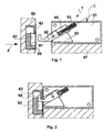
- Figure 1 shows a side view of the latch device of the invention in a first operating position;
- Figure 2 shows a side view of the latch device in Figure 1 in a second operating position;
- Figure 3 shows an exploded axonometric view of the latch device in Figure 1;
- Figure 4 shows an axonometric view of an element forming the latch device in Figure 1;
- Figure 5 shows an axonometric view of an element forming the latch device in Figure 1;
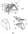
- Figure 6 shows a side section of an embodiment of the latch device of the invention;
- Figure 7 shows an exploded axonometric view of the latch device in Figure 6;
- Figure 8 shows four different operating phases of the latch according to the invention.
- With reference to the Figures cited, a latch device is represented, globally referenced with the reference T, generally, although not necessarily, fixed in one part thereof to a suitable structure of
furniture 57, and in another part thereof to adoor 58. It is however possible to kinetically invert the furniture parts on which the two parts forming the latch are fixed, however without departing from the sphere of the invention. - The part of the latch T destined to be fixed to the
furniture 57 with suitable means that are not described in detail, comprises a box orcontainer 51 with a first groove or longitudinal cavity defining asliding guide 60. In theguide 60 there are theslider 52, thehelical spring 53 or another similar spring, which rests with one end on a shoulder or end of the guide and with the other end on theslider 52, on which ashank 65 is provided to improve contact with thespring 53. Thecontainer 51 has acover 54 to close the open side of theguide 60. - In an advantageous embodiment part of the container is provided with an
insert 50 essentially triangular in shape, which forms one side of theguide 60, or part of one side, to facilitate manufacture and assembly. However, theinsert 50 may alternatively also be eliminated to produce thecontainer 51 in one piece. - The
guide 60 is inclined, with respect to the direction of application of the force F acting on theslider 52, of an angle α, predetermined and defined according to the door or furniture part to be opened. - There is provided, on the side of the
guide 60, a second groove defining atrack 40 with different depths according to areas defining a path with a cam profile. - The
slider 52 also has aseat 71 with a rectangular plane, closed on the bottom, in which is placed aflat spring 72 bent in the shape of a V, on the outward facing side of which aball 73 rests. Theflat spring 72 thus pushes theball 73 towards the bottom of thetrack 40 to make it travel along the path. Athird groove 67 facilitates attachment of thespring 72 in itsseat 71. - The
track 40 is constituted by a longerlongitudinal section 27, the bottom of which varies in thickness and forms an inclined ramp terminating with astep 28, which marks the limit separating it from atransverse section 29 slightly curved in the plane. The bottom of thetransverse section 29 has two sections withlevels 29', 29" slightly staggered, in the deepest of which 29" aseat 30 is provided in the shape of a spherical cap. Running parallel to thesection 27 is a second shorterlongitudinal section 31, which joins with the front part of thesection 27 by means of asection 32, the bottom of which is inclined, and at the end of which a shortinclined ramp 33 is positioned to form afurther step 34 in the connection point with thesection 27. - Fig. 8 shows four positions of the latch, which show its operation between an open position and a locked position and again in an open position. The positions are indicated with the letters a), b), c), d) and also define four corresponding positions of the
ball 73 along the track of the cover. Here the positions are shown as transparency views through the surface of theinsert 50. In position a) thehook 68 is in the outermost position, and therefore the hookingelement 59 and the door connected to it can move freely. When thedoor 58 is pushed towards the closing position, the hookingelement 59 knocks against thehook 68 with a force F, the component thereof parallel to the axis of theguide 60 pushes theslider 52 inside theguide 60 compressing thespring 53 to reach the position shown in Figure 2. - During this sliding, the
hook 68 engages thehooking edge 62 of the hookingelement 59, catching it. At this point as theball 73 cannot travel along thesection 32 as it is obstructed by thestep 34, it travels along theramp 27 and passes beyond thestep 28. Here inclination of the shank of the V-shaped spring 72 pushes theball 73 along thedeepest part 29" of thesection 29 until it enters theseat 30 in the form of spherical cap, becoming locked in the position c). In this position theslider 52 cannot slide in the groove and thehook 68 locks thehooking element 59, so that the furniture part remains locked in its closed position even if no external force is applied thereto. - The operation to open the door or drawer is instead carried out in the following way. After a successive slight thrust in the closing direction of the door, the
ball 73 is moved from theseat 30 towards the shallowest part 29' of thesection 29 and thespring 72 pushes it into the position d). By removing the external force on the furniture part, thehelical spring 53 pushes theslider 52 towards the outside and theball 73 travels along thesections ramp 33 and thestep 34, returning to the initial condition a) wherein the furniture part is released. - Advantageously, the hooking element can be constituted by a
cavity 61 partly open towards the opposed flat surfaces so as to easily produce thehooking edge 62, even with a moulding process. Thebottom 63 constitutes the thrust element of thehook 68 when the latch is in operation, making it slide in combination with the oblique movement in the inclined direction of the angle α, until it is positioned behind thehooking edge 62, as shown in Figures 2 and 6. - The
cover 54 is also provided withshanks 76 suitable to be housed incorresponding holes 75 of thecontainer 51 to allow integral assembly of the two parts. - An embodiment of the latch conforming to the invention is shown in Figures 6 and 7. The
container 81 has an essentially hollow trapezoidal shape inside which asliding guide 90 is placed. One of the sides of the container is open and, in the mounted position of the latch, this side is closed by atriangular insert 80, one of the sides thereof defining a side of theguide 90. Thetriangular insert 80 also has the function of resting on the furniture, with asuitable reference stop 84. Advantageously, although not necessarily, thetrack 40 can be provided on one side of thetriangular insert 80. This element is suitably fixed to thecontainer 81 by means of fixing means of known type, not shown. - From the description above it is apparent that the latch device of the invention is composed of a minimum number of components, is simple to assemble and can be mounted on furniture with an operation that is not difficult even for inexperienced personnel.
- The particular embodiments described herein do not limit the content of this application, which covers all the embodiments of the invention defined by the claims.
Claims (5)
- Opening and closing latch device (T), adapted to facilitate closing and/or opening of a movable part (58) of furniture with respect to the furniture (57), comprising a container (51, 81) defining an intemal cavity with at least one open side and comprising a sliding guide (60, 90),
characterised in that it also comprises:- a sliding element (52), placed in the sliding guide and comprising a hook (68) at a first end, suitable to catch a hooking element (59) integral with said movable part (58),- elastic means (53), placed between the sliding element (52) and the container (51), so that the elastic means (53) exert an elastic force on the sliding element (52) suitable to make it slide, reacting on said container (51),- a track (40), placed on one side of the sliding guide (60, 90), with surface of the bottom defining a cam path and the plan layout of which forms a closed geometrical figure,- tappet means (73), integral with the sliding element (52), suitable to travel along the cam path, so as to define a number of positions of the sliding element (52), corresponding to a release position, a lock position and two intermediate opening and closing positions of said movable part (58),and in that the sliding guide (60, 90) is inclined of an angle (α) with respect to the direction along which a closing and opening movement takes place between the movable part (58) and the furniture (57). - Latch device according the claim 1, wherein the container (51, 81) comprises an insert (50) essentially triangular in shape, one side of which defines a side of the sliding guide (60, 90).
- Latch device according the claim 2, wherein the track (40) is provided on the side of the sliding guide (60, 90) constituted by said insert (50, 80).
- Latch device according the claim 3, wherein the container (51) comprises a cover (54), forming one of the sides of the cavity, and a base with connection means (76) suitable to join the cover to the base.
- Latch device according the claim 4, wherein the tappet means are formed of a ball (73) held in pressure against the bottom of the track (40) by a spring (72).
Priority Applications (1)
| Application Number | Priority Date | Filing Date | Title |
|---|---|---|---|
| SI200430096T SI1583879T1 (en) | 2003-10-15 | 2004-10-14 | Opening and closing latch device for furniture |
Applications Claiming Priority (3)
| Application Number | Priority Date | Filing Date | Title |
|---|---|---|---|
| ITRM20030171U | 2003-10-15 | ||
| IT000171U ITRM20030171U1 (en) | 2003-10-15 | 2003-10-15 | OPENING AND CLOSING DEVICE FOR FURNITURE. |
| PCT/EP2004/052535 WO2005038177A1 (en) | 2003-10-15 | 2004-10-14 | Opening and closing latch device for furniture |
Publications (2)
| Publication Number | Publication Date |
|---|---|
| EP1583879A1 EP1583879A1 (en) | 2005-10-12 |
| EP1583879B1 true EP1583879B1 (en) | 2006-08-09 |
Family
ID=30131515
Family Applications (1)
| Application Number | Title | Priority Date | Filing Date |
|---|---|---|---|
| EP04791222A Expired - Lifetime EP1583879B1 (en) | 2003-10-15 | 2004-10-14 | Opening and closing latch device for furniture |
Country Status (12)
| Country | Link |
|---|---|
| US (1) | US7325844B2 (en) |
| EP (1) | EP1583879B1 (en) |
| JP (1) | JP2007508479A (en) |
| KR (1) | KR20060119698A (en) |
| CN (1) | CN1723327B (en) |
| AT (1) | ATE335904T1 (en) |
| BR (1) | BRPI0406482A (en) |
| DE (1) | DE602004001855T2 (en) |
| ES (1) | ES2274491T3 (en) |
| IT (1) | ITRM20030171U1 (en) |
| TW (1) | TWI327899B (en) |
| WO (1) | WO2005038177A1 (en) |
Cited By (1)
| Publication number | Priority date | Publication date | Assignee | Title |
|---|---|---|---|---|
| DE102014221752A1 (en) | 2014-10-27 | 2016-04-28 | Aug. Winkhaus Gmbh & Co. Kg | Detent device for a window or a door |
Families Citing this family (23)
| Publication number | Priority date | Publication date | Assignee | Title |
|---|---|---|---|---|
| TWI264927B (en) * | 2005-05-12 | 2006-10-21 | Benq Corp | Electronic apparatus capable of fabricating a key module easily |
| WO2006132613A1 (en) * | 2005-06-03 | 2006-12-14 | Linpac Materials Handling | Container assembly and latch apparatus, and related methods |
| ITPN20050096A1 (en) * | 2005-12-29 | 2007-06-30 | Verardo Spa | MOBILE EQUIPPED WITH A DEVICE FOR THE CLOSING AND OPENING OF SLIDING DOORS. |
| DE102006002951B4 (en) * | 2006-01-21 | 2008-10-16 | Zimmer, Günther | Damping set for revolving doors |
| DE102006002952B4 (en) * | 2006-01-21 | 2008-10-16 | Zimmer, Günther | Door pull set for revolving doors |
| WO2008147870A2 (en) * | 2007-05-24 | 2008-12-04 | Illinois Tool Works Inc. | Gasket-compensating latch mechanism |
| US7669820B2 (en) * | 2007-07-06 | 2010-03-02 | Qisda Corporation | Supporting device and electronic apparatus using the same |
| KR100888167B1 (en) * | 2008-03-14 | 2009-03-10 | 동우정밀(주) | Door opening and closing unit |
| TWI395119B (en) * | 2009-12-23 | 2013-05-01 | Compal Electronics Inc | Push-push type stylus eject mechanism |
| DE102010031750B4 (en) * | 2010-07-21 | 2012-07-12 | Eads Deutschland Gmbh | Detachable connection arrangement for attaching externally droppable loads to an aircraft |
| US9243427B2 (en) | 2011-01-24 | 2016-01-26 | Carefusion 303, Inc. | Self-aligning modular latch |
| CN103176519A (en) * | 2011-12-26 | 2013-06-26 | 鸿富锦精密工业(深圳)有限公司 | Electronic device |
| US9235234B2 (en) * | 2012-08-20 | 2016-01-12 | Quanta Computer Inc. | Detaching mechanism and laptop shell assembly |
| CN104323575B (en) * | 2014-10-17 | 2017-06-06 | 吴肖颜 | A kind of wooden table for being easy to short distance to carry |
| AT517063B1 (en) * | 2015-07-07 | 2016-11-15 | Blum Gmbh Julius | Drive device for a movable furniture part |
| CN107086481A (en) * | 2016-12-05 | 2017-08-22 | 温岭市仁全机械设备有限公司 | A kind of firm electric power drawer cabinet equipment |
| CN107086477A (en) * | 2016-12-05 | 2017-08-22 | 温岭市仁全机械设备有限公司 | One kind runs smoothly electric power drawer cabinet |
| US11149477B2 (en) | 2017-06-28 | 2021-10-19 | Snap-On Incorporated | Latch and method of installing a latch |
| CN109209075B (en) * | 2018-08-07 | 2020-07-10 | 广东坚朗五金制品股份有限公司 | Automatic locking devices and doors and windows |
| DE102019133605A1 (en) * | 2019-12-09 | 2021-06-10 | Paul Hettich Gmbh & Co. Kg | Device for the detachable fixation of a front panel on a side frame and drawer |
| CN111619926B (en) * | 2020-05-26 | 2021-12-28 | 青岛黄海学院 | Dedicated teaching aid placer of getting of being convenient for of mathematics teaching |
| US12043456B2 (en) * | 2021-08-17 | 2024-07-23 | United Parcel Service Of America, Inc. | Latching mechanisms, storage receptacles with latching mechanisms, and methods of manufacturing and using the same |
| CN116446728A (en) * | 2023-05-31 | 2023-07-18 | 广东美的厨房电器制造有限公司 | Door assembly of cooking utensil and cooking utensil |
Family Cites Families (24)
| Publication number | Priority date | Publication date | Assignee | Title |
|---|---|---|---|---|
| US983647A (en) * | 1910-02-16 | 1911-02-07 | Leroy Romines | Latch. |
| US1859003A (en) * | 1928-09-29 | 1932-05-17 | Barrett Co | Container and coacting and self-fastening cap therefor |
| US2670981A (en) * | 1952-01-31 | 1954-03-02 | Douglas L Wenham | Latch mechanism |
| JPS5756957U (en) * | 1980-09-22 | 1982-04-03 | ||
| JPS6131581A (en) * | 1984-07-23 | 1986-02-14 | 株式会社 ニフコ | Lock apparatus |
| JPH0412957Y2 (en) * | 1985-04-01 | 1992-03-26 | ||
| JPH0519484Y2 (en) * | 1985-10-16 | 1993-05-21 | ||
| US4792165A (en) * | 1987-09-17 | 1988-12-20 | Futaba Kinzoku Kogyo Kabushiki Kaisha | Push latch device |
| JPH0249749Y2 (en) * | 1988-03-31 | 1990-12-27 | ||
| JPH0441880A (en) * | 1990-06-07 | 1992-02-12 | Inoue Kanamono Kk | Push latch device |
| US5072974A (en) * | 1991-02-07 | 1991-12-17 | The Stanley Works | Push to close latch for self-cleaning oven |
| CN2111336U (en) * | 1991-09-07 | 1992-07-29 | 宗恩泽 | Anti-prizing double-tongue door lock device |
| US5401067A (en) * | 1992-06-10 | 1995-03-28 | Nifco, Inc. | Latch device |
| US5518282A (en) * | 1993-11-30 | 1996-05-21 | Koei Sangyo Co., Ltd. | Locking device for open-close mechanism of a cabinet |
| FR2739268B1 (en) | 1995-10-03 | 1997-12-19 | Piole | DEVICE FOR OPENING AND CLOSING A MOBILE ELEMENT IN RELATION TO A CONTAINER, AND ITS APPLICATION TO MOVABLE DRAWERS |
| DE19753319C2 (en) | 1996-12-02 | 2001-05-31 | Sarnatech Paulmann & Crone | Device that can be locked and unlocked by external force |
| JPH10220091A (en) * | 1997-02-03 | 1998-08-18 | Tokyo Magnet Oyo Seihin Kk | Lock device for opening and closing door |
| US6068307A (en) * | 1998-06-16 | 2000-05-30 | Micron Electronics, Inc. | Closure system for devices having a stylus |
| JP3559954B2 (en) * | 1999-03-05 | 2004-09-02 | 株式会社ケンウッド | Push latch mounting structure |
| DE19910564C2 (en) * | 1999-03-10 | 2003-06-26 | Dometic Gmbh | Safety lock, in particular for doors in built-in areas of mobile homes |
| JP4473403B2 (en) * | 2000-03-23 | 2010-06-02 | 株式会社ニフコ | Latch device |
| CN2446231Y (en) * | 2000-09-15 | 2001-09-05 | 北京第二开关厂 | Rod lock for equipment drawer |
| US6659514B2 (en) * | 2001-05-04 | 2003-12-09 | Thyssen Elevator Capital Corp. | Swinging elevator hatchway door interlock |
| US6588809B1 (en) * | 2002-04-29 | 2003-07-08 | Jay S. Derman | Push-to-release cabinet door latch |
-
2003
- 2003-10-15 IT IT000171U patent/ITRM20030171U1/en unknown
-
2004
- 2004-10-14 WO PCT/EP2004/052535 patent/WO2005038177A1/en not_active Ceased
- 2004-10-14 ES ES04791222T patent/ES2274491T3/en not_active Expired - Lifetime
- 2004-10-14 BR BRPI0406482 patent/BRPI0406482A/en not_active Application Discontinuation
- 2004-10-14 DE DE200460001855 patent/DE602004001855T2/en not_active Expired - Lifetime
- 2004-10-14 CN CN2004800015641A patent/CN1723327B/en not_active Expired - Fee Related
- 2004-10-14 KR KR1020057010904A patent/KR20060119698A/en not_active Withdrawn
- 2004-10-14 EP EP04791222A patent/EP1583879B1/en not_active Expired - Lifetime
- 2004-10-14 US US10/539,688 patent/US7325844B2/en not_active Expired - Fee Related
- 2004-10-14 JP JP2006534759A patent/JP2007508479A/en active Pending
- 2004-10-14 AT AT04791222T patent/ATE335904T1/en active
- 2004-10-15 TW TW93131328A patent/TWI327899B/en not_active IP Right Cessation
Cited By (2)
| Publication number | Priority date | Publication date | Assignee | Title |
|---|---|---|---|---|
| DE102014221752A1 (en) | 2014-10-27 | 2016-04-28 | Aug. Winkhaus Gmbh & Co. Kg | Detent device for a window or a door |
| EP3015627A1 (en) | 2014-10-27 | 2016-05-04 | Aug. Winkhaus GmbH & Co. KG | Catch device for a window or a door |
Also Published As
| Publication number | Publication date |
|---|---|
| US20060087128A1 (en) | 2006-04-27 |
| JP2007508479A (en) | 2007-04-05 |
| EP1583879A1 (en) | 2005-10-12 |
| CN1723327A (en) | 2006-01-18 |
| HK1084429A1 (en) | 2006-07-28 |
| ITRM20030171V0 (en) | 2003-10-15 |
| DE602004001855T2 (en) | 2007-11-29 |
| ITRM20030171U1 (en) | 2005-04-16 |
| CN1723327B (en) | 2011-04-13 |
| TWI327899B (en) | 2010-08-01 |
| TW200522895A (en) | 2005-07-16 |
| US7325844B2 (en) | 2008-02-05 |
| WO2005038177A1 (en) | 2005-04-28 |
| KR20060119698A (en) | 2006-11-24 |
| ES2274491T3 (en) | 2007-05-16 |
| BRPI0406482A (en) | 2005-12-06 |
| DE602004001855D1 (en) | 2006-09-21 |
| ATE335904T1 (en) | 2006-09-15 |
Similar Documents
| Publication | Publication Date | Title |
|---|---|---|
| EP1583879B1 (en) | Opening and closing latch device for furniture | |
| EP1377721B1 (en) | Load floor latch | |
| US4616861A (en) | Lock device | |
| EP1664466A1 (en) | Opening and closing latch device for furniture | |
| US4882919A (en) | Flush mounted panel lock construction | |
| US20060255596A1 (en) | Flush handle latch mechanism | |
| CN101720375A (en) | Drawer lock mechanism | |
| US7261342B2 (en) | Automatically locking window latch | |
| CA2471315A1 (en) | Lock for lever-handled door latch | |
| KR102178474B1 (en) | Furniture door handles with door locking and unlocking means | |
| JPH022853Y2 (en) | ||
| JPH08170460A (en) | Crime preventive lock for sliding door | |
| KR100738735B1 (en) | A device for closing and opening moving part of a piece of furniture | |
| EP2248969A1 (en) | Lock and modification package for a lock | |
| KR200196853Y1 (en) | Window lock system | |
| JPS6233890Y2 (en) | ||
| EP3806124A1 (en) | Actuator unit and safety switch | |
| KR200157884Y1 (en) | One touch button locking device | |
| HK1084429B (en) | Opening and closing latch device for furniture | |
| KR200386711Y1 (en) | Window Locking Device | |
| DK0952282T3 (en) | Door lock with actuator and associated key | |
| KR200424013Y1 (en) | Door lock | |
| KR100809810B1 (en) | Door lock | |
| KR100246209B1 (en) | Device for opening or closing a door | |
| JPS5828132Y2 (en) | Door locking rod protruding control |
Legal Events
| Date | Code | Title | Description |
|---|---|---|---|
| PUAI | Public reference made under article 153(3) epc to a published international application that has entered the european phase |
Free format text: ORIGINAL CODE: 0009012 |
|
| 17P | Request for examination filed |
Effective date: 20050614 |
|
| AK | Designated contracting states |
Kind code of ref document: A1 Designated state(s): AT BE BG CH CY CZ DE DK EE ES FI FR GB GR HU IE IT LI LU MC NL PL PT RO SE SI SK TR |
|
| AX | Request for extension of the european patent |
Extension state: AL HR LT LV MK |
|
| GRAP | Despatch of communication of intention to grant a patent |
Free format text: ORIGINAL CODE: EPIDOSNIGR1 |
|
| GRAS | Grant fee paid |
Free format text: ORIGINAL CODE: EPIDOSNIGR3 |
|
| GRAA | (expected) grant |
Free format text: ORIGINAL CODE: 0009210 |
|
| AK | Designated contracting states |
Kind code of ref document: B1 Designated state(s): AT BE BG CH CY CZ DE DK EE ES FI FR GB GR HU IE IT LI LU MC NL PL PT RO SE SI SK TR |
|
| DAX | Request for extension of the european patent (deleted) | ||
| PG25 | Lapsed in a contracting state [announced via postgrant information from national office to epo] |
Ref country code: IT Free format text: LAPSE BECAUSE OF FAILURE TO SUBMIT A TRANSLATION OF THE DESCRIPTION OR TO PAY THE FEE WITHIN THE PRESCRIBED TIME-LIMIT;WARNING: LAPSES OF ITALIAN PATENTS WITH EFFECTIVE DATE BEFORE 2007 MAY HAVE OCCURRED AT ANY TIME BEFORE 2007. THE CORRECT EFFECTIVE DATE MAY BE DIFFERENT FROM THE ONE RECORDED. Effective date: 20060809 Ref country code: LI Free format text: LAPSE BECAUSE OF FAILURE TO SUBMIT A TRANSLATION OF THE DESCRIPTION OR TO PAY THE FEE WITHIN THE PRESCRIBED TIME-LIMIT Effective date: 20060809 Ref country code: CH Free format text: LAPSE BECAUSE OF FAILURE TO SUBMIT A TRANSLATION OF THE DESCRIPTION OR TO PAY THE FEE WITHIN THE PRESCRIBED TIME-LIMIT Effective date: 20060809 Ref country code: CZ Free format text: LAPSE BECAUSE OF FAILURE TO SUBMIT A TRANSLATION OF THE DESCRIPTION OR TO PAY THE FEE WITHIN THE PRESCRIBED TIME-LIMIT Effective date: 20060809 Ref country code: NL Free format text: LAPSE BECAUSE OF FAILURE TO SUBMIT A TRANSLATION OF THE DESCRIPTION OR TO PAY THE FEE WITHIN THE PRESCRIBED TIME-LIMIT Effective date: 20060809 Ref country code: SK Free format text: LAPSE BECAUSE OF FAILURE TO SUBMIT A TRANSLATION OF THE DESCRIPTION OR TO PAY THE FEE WITHIN THE PRESCRIBED TIME-LIMIT Effective date: 20060809 Ref country code: FI Free format text: LAPSE BECAUSE OF FAILURE TO SUBMIT A TRANSLATION OF THE DESCRIPTION OR TO PAY THE FEE WITHIN THE PRESCRIBED TIME-LIMIT Effective date: 20060809 Ref country code: PL Free format text: LAPSE BECAUSE OF FAILURE TO SUBMIT A TRANSLATION OF THE DESCRIPTION OR TO PAY THE FEE WITHIN THE PRESCRIBED TIME-LIMIT Effective date: 20060809 Ref country code: BE Free format text: LAPSE BECAUSE OF FAILURE TO SUBMIT A TRANSLATION OF THE DESCRIPTION OR TO PAY THE FEE WITHIN THE PRESCRIBED TIME-LIMIT Effective date: 20060809 Ref country code: RO Free format text: LAPSE BECAUSE OF FAILURE TO SUBMIT A TRANSLATION OF THE DESCRIPTION OR TO PAY THE FEE WITHIN THE PRESCRIBED TIME-LIMIT Effective date: 20060809 |
|
| REG | Reference to a national code |
Ref country code: GB Ref legal event code: FG4D |
|
| REG | Reference to a national code |
Ref country code: CH Ref legal event code: EP |
|
| REG | Reference to a national code |
Ref country code: IE Ref legal event code: FG4D |
|
| REF | Corresponds to: |
Ref document number: 602004001855 Country of ref document: DE Date of ref document: 20060921 Kind code of ref document: P |
|
| PG25 | Lapsed in a contracting state [announced via postgrant information from national office to epo] |
Ref country code: IE Free format text: LAPSE BECAUSE OF NON-PAYMENT OF DUE FEES Effective date: 20061016 |
|
| PG25 | Lapsed in a contracting state [announced via postgrant information from national office to epo] |
Ref country code: MC Free format text: LAPSE BECAUSE OF NON-PAYMENT OF DUE FEES Effective date: 20061031 |
|
| PG25 | Lapsed in a contracting state [announced via postgrant information from national office to epo] |
Ref country code: BG Free format text: LAPSE BECAUSE OF FAILURE TO SUBMIT A TRANSLATION OF THE DESCRIPTION OR TO PAY THE FEE WITHIN THE PRESCRIBED TIME-LIMIT Effective date: 20061109 Ref country code: DK Free format text: LAPSE BECAUSE OF FAILURE TO SUBMIT A TRANSLATION OF THE DESCRIPTION OR TO PAY THE FEE WITHIN THE PRESCRIBED TIME-LIMIT Effective date: 20061109 Ref country code: SE Free format text: LAPSE BECAUSE OF FAILURE TO SUBMIT A TRANSLATION OF THE DESCRIPTION OR TO PAY THE FEE WITHIN THE PRESCRIBED TIME-LIMIT Effective date: 20061109 |
|
| PG25 | Lapsed in a contracting state [announced via postgrant information from national office to epo] |
Ref country code: PT Free format text: LAPSE BECAUSE OF FAILURE TO SUBMIT A TRANSLATION OF THE DESCRIPTION OR TO PAY THE FEE WITHIN THE PRESCRIBED TIME-LIMIT Effective date: 20070109 |
|
| NLV1 | Nl: lapsed or annulled due to failure to fulfill the requirements of art. 29p and 29m of the patents act | ||
| REG | Reference to a national code |
Ref country code: CH Ref legal event code: PL |
|
| EN | Fr: translation not filed | ||
| REG | Reference to a national code |
Ref country code: ES Ref legal event code: FG2A Ref document number: 2274491 Country of ref document: ES Kind code of ref document: T3 |
|
| PLBE | No opposition filed within time limit |
Free format text: ORIGINAL CODE: 0009261 |
|
| STAA | Information on the status of an ep patent application or granted ep patent |
Free format text: STATUS: NO OPPOSITION FILED WITHIN TIME LIMIT |
|
| 26N | No opposition filed |
Effective date: 20070510 |
|
| PG25 | Lapsed in a contracting state [announced via postgrant information from national office to epo] |
Ref country code: FR Free format text: LAPSE BECAUSE OF FAILURE TO SUBMIT A TRANSLATION OF THE DESCRIPTION OR TO PAY THE FEE WITHIN THE PRESCRIBED TIME-LIMIT Effective date: 20070511 Ref country code: GR Free format text: LAPSE BECAUSE OF FAILURE TO SUBMIT A TRANSLATION OF THE DESCRIPTION OR TO PAY THE FEE WITHIN THE PRESCRIBED TIME-LIMIT Effective date: 20061110 |
|
| PG25 | Lapsed in a contracting state [announced via postgrant information from national office to epo] |
Ref country code: EE Free format text: LAPSE BECAUSE OF FAILURE TO SUBMIT A TRANSLATION OF THE DESCRIPTION OR TO PAY THE FEE WITHIN THE PRESCRIBED TIME-LIMIT Effective date: 20060809 |
|
| PG25 | Lapsed in a contracting state [announced via postgrant information from national office to epo] |
Ref country code: LU Free format text: LAPSE BECAUSE OF NON-PAYMENT OF DUE FEES Effective date: 20061014 Ref country code: TR Free format text: LAPSE BECAUSE OF FAILURE TO SUBMIT A TRANSLATION OF THE DESCRIPTION OR TO PAY THE FEE WITHIN THE PRESCRIBED TIME-LIMIT Effective date: 20060809 Ref country code: HU Free format text: LAPSE BECAUSE OF FAILURE TO SUBMIT A TRANSLATION OF THE DESCRIPTION OR TO PAY THE FEE WITHIN THE PRESCRIBED TIME-LIMIT Effective date: 20070210 |
|
| PG25 | Lapsed in a contracting state [announced via postgrant information from national office to epo] |
Ref country code: FR Free format text: LAPSE BECAUSE OF FAILURE TO SUBMIT A TRANSLATION OF THE DESCRIPTION OR TO PAY THE FEE WITHIN THE PRESCRIBED TIME-LIMIT Effective date: 20060809 Ref country code: CY Free format text: LAPSE BECAUSE OF FAILURE TO SUBMIT A TRANSLATION OF THE DESCRIPTION OR TO PAY THE FEE WITHIN THE PRESCRIBED TIME-LIMIT Effective date: 20060809 |
|
| GBPC | Gb: european patent ceased through non-payment of renewal fee |
Effective date: 20081014 |
|
| PG25 | Lapsed in a contracting state [announced via postgrant information from national office to epo] |
Ref country code: IT Free format text: LAPSE BECAUSE OF NON-PAYMENT OF DUE FEES Effective date: 20081014 |
|
| PG25 | Lapsed in a contracting state [announced via postgrant information from national office to epo] |
Ref country code: GB Free format text: LAPSE BECAUSE OF NON-PAYMENT OF DUE FEES Effective date: 20081014 |
|
| PGFP | Annual fee paid to national office [announced via postgrant information from national office to epo] |
Ref country code: SI Payment date: 20100901 Year of fee payment: 7 |
|
| PGRI | Patent reinstated in contracting state [announced from national office to epo] |
Ref country code: IT Effective date: 20110616 |
|
| REG | Reference to a national code |
Ref country code: SI Ref legal event code: KO00 Effective date: 20130516 |
|
| PG25 | Lapsed in a contracting state [announced via postgrant information from national office to epo] |
Ref country code: SI Free format text: LAPSE BECAUSE OF NON-PAYMENT OF DUE FEES Effective date: 20121015 |
|
| PGFP | Annual fee paid to national office [announced via postgrant information from national office to epo] |
Ref country code: IT Payment date: 20221020 Year of fee payment: 19 Ref country code: ES Payment date: 20221102 Year of fee payment: 19 Ref country code: DE Payment date: 20221027 Year of fee payment: 19 Ref country code: AT Payment date: 20220921 Year of fee payment: 19 |
|
| P01 | Opt-out of the competence of the unified patent court (upc) registered |
Effective date: 20230515 |
|
| REG | Reference to a national code |
Ref country code: DE Ref legal event code: R119 Ref document number: 602004001855 Country of ref document: DE |
|
| REG | Reference to a national code |
Ref country code: AT Ref legal event code: MM01 Ref document number: 335904 Country of ref document: AT Kind code of ref document: T Effective date: 20231014 |
|
| PG25 | Lapsed in a contracting state [announced via postgrant information from national office to epo] |
Ref country code: AT Free format text: LAPSE BECAUSE OF NON-PAYMENT OF DUE FEES Effective date: 20231014 |
|
| PG25 | Lapsed in a contracting state [announced via postgrant information from national office to epo] |
Ref country code: DE Free format text: LAPSE BECAUSE OF NON-PAYMENT OF DUE FEES Effective date: 20240501 Ref country code: AT Free format text: LAPSE BECAUSE OF NON-PAYMENT OF DUE FEES Effective date: 20231014 |
|
| REG | Reference to a national code |
Ref country code: ES Ref legal event code: FD2A Effective date: 20241128 |
|
| PG25 | Lapsed in a contracting state [announced via postgrant information from national office to epo] |
Ref country code: IT Free format text: LAPSE BECAUSE OF NON-PAYMENT OF DUE FEES Effective date: 20231014 |
|
| PG25 | Lapsed in a contracting state [announced via postgrant information from national office to epo] |
Ref country code: IT Free format text: LAPSE BECAUSE OF NON-PAYMENT OF DUE FEES Effective date: 20231014 |
|
| PG25 | Lapsed in a contracting state [announced via postgrant information from national office to epo] |
Ref country code: ES Free format text: LAPSE BECAUSE OF NON-PAYMENT OF DUE FEES Effective date: 20231015 |
|
| PG25 | Lapsed in a contracting state [announced via postgrant information from national office to epo] |
Ref country code: ES Free format text: LAPSE BECAUSE OF NON-PAYMENT OF DUE FEES Effective date: 20231015 |