EP1583211A2 - Superconductor quench monitoring and control system and method of operating the same - Google Patents
Superconductor quench monitoring and control system and method of operating the same Download PDFInfo
- Publication number
- EP1583211A2 EP1583211A2 EP05250407A EP05250407A EP1583211A2 EP 1583211 A2 EP1583211 A2 EP 1583211A2 EP 05250407 A EP05250407 A EP 05250407A EP 05250407 A EP05250407 A EP 05250407A EP 1583211 A2 EP1583211 A2 EP 1583211A2
- Authority
- EP
- European Patent Office
- Prior art keywords
- coil
- superconductive coil
- temperature
- temperature sensor
- superconductive
- Prior art date
- Legal status (The legal status is an assumption and is not a legal conclusion. Google has not performed a legal analysis and makes no representation as to the accuracy of the status listed.)
- Withdrawn
Links
- 238000010791 quenching Methods 0.000 title claims description 61
- 238000000034 method Methods 0.000 title claims description 22
- 238000012544 monitoring process Methods 0.000 title claims description 8
- 239000002887 superconductor Substances 0.000 title description 2
- 230000005291 magnetic effect Effects 0.000 claims description 13
- 230000000694 effects Effects 0.000 claims description 6
- 230000000171 quenching effect Effects 0.000 description 20
- RYGMFSIKBFXOCR-UHFFFAOYSA-N Copper Chemical compound [Cu] RYGMFSIKBFXOCR-UHFFFAOYSA-N 0.000 description 8
- 229910052802 copper Inorganic materials 0.000 description 8
- 239000010949 copper Substances 0.000 description 8
- 238000001514 detection method Methods 0.000 description 8
- 238000010438 heat treatment Methods 0.000 description 6
- 239000000463 material Substances 0.000 description 5
- 238000009413 insulation Methods 0.000 description 4
- 238000010248 power generation Methods 0.000 description 4
- 239000004020 conductor Substances 0.000 description 3
- 239000007787 solid Substances 0.000 description 3
- 230000001939 inductive effect Effects 0.000 description 2
- 230000003213 activating effect Effects 0.000 description 1
- 230000015556 catabolic process Effects 0.000 description 1
- 230000008859 change Effects 0.000 description 1
- 238000001816 cooling Methods 0.000 description 1
- 238000006731 degradation reaction Methods 0.000 description 1
- 230000005611 electricity Effects 0.000 description 1
- 239000003302 ferromagnetic material Substances 0.000 description 1
- 230000009931 harmful effect Effects 0.000 description 1
- 230000002427 irreversible effect Effects 0.000 description 1
- 230000035699 permeability Effects 0.000 description 1
- BASFCYQUMIYNBI-UHFFFAOYSA-N platinum Chemical compound [Pt] BASFCYQUMIYNBI-UHFFFAOYSA-N 0.000 description 1
- 230000008569 process Effects 0.000 description 1
- 230000009467 reduction Effects 0.000 description 1
- 230000035945 sensitivity Effects 0.000 description 1
- 239000002689 soil Substances 0.000 description 1
- 230000002459 sustained effect Effects 0.000 description 1
- 230000007704 transition Effects 0.000 description 1
Images


Classifications
-
- H—ELECTRICITY
- H02—GENERATION; CONVERSION OR DISTRIBUTION OF ELECTRIC POWER
- H02K—DYNAMO-ELECTRIC MACHINES
- H02K55/00—Dynamo-electric machines having windings operating at cryogenic temperatures
- H02K55/02—Dynamo-electric machines having windings operating at cryogenic temperatures of the synchronous type
- H02K55/04—Dynamo-electric machines having windings operating at cryogenic temperatures of the synchronous type with rotating field windings
-
- H—ELECTRICITY
- H02—GENERATION; CONVERSION OR DISTRIBUTION OF ELECTRIC POWER
- H02K—DYNAMO-ELECTRIC MACHINES
- H02K11/00—Structural association of dynamo-electric machines with electric components or with devices for shielding, monitoring or protection
- H02K11/20—Structural association of dynamo-electric machines with electric components or with devices for shielding, monitoring or protection for measuring, monitoring, testing, protecting or switching
- H02K11/25—Devices for sensing temperature, or actuated thereby
-
- Y—GENERAL TAGGING OF NEW TECHNOLOGICAL DEVELOPMENTS; GENERAL TAGGING OF CROSS-SECTIONAL TECHNOLOGIES SPANNING OVER SEVERAL SECTIONS OF THE IPC; TECHNICAL SUBJECTS COVERED BY FORMER USPC CROSS-REFERENCE ART COLLECTIONS [XRACs] AND DIGESTS
- Y02—TECHNOLOGIES OR APPLICATIONS FOR MITIGATION OR ADAPTATION AGAINST CLIMATE CHANGE
- Y02E—REDUCTION OF GREENHOUSE GAS [GHG] EMISSIONS, RELATED TO ENERGY GENERATION, TRANSMISSION OR DISTRIBUTION
- Y02E40/00—Technologies for an efficient electrical power generation, transmission or distribution
- Y02E40/60—Superconducting electric elements or equipment; Power systems integrating superconducting elements or equipment
Definitions
- the invention relates generally to a rotating electrical machine having a superconductive coil, and in particular to a system and method for quench monitoring and control of a superconductive rotor coil of a rotating electrical machine.
- a superconductor is a material that will conduct electricity with no electrical resistance. Most electrical conductors have some electrical resistance. However, electrical resistance is an undesirable property for a conductor to have because the electrical resistance consumes energy as heat. Superconductivity occurs in certain materials when the material is cooled below a critical temperature.
- the rotors of rotating electrical machines typically use an electrical current flowing through a coil to produce a magnetic field.
- the amount of electrical current that flows through the rotor coil may be significant.
- a portion of the electrical current is consumed as resistive heating, reducing the efficiency of the power generation system. Consequently, superconductive rotor coils have been developed for use in rotating electric machines.
- the coil At ambient temperatures, the coil has a defined electrical resistance. However, when cooled below the critical temperature, the coil enters a superconducting state and loses its electrical resistance.
- a portion of the superconductive rotor coil may change from the superconducting state to a normal resistive state.
- the portion of the coil in the normal resistive state will cause resistive heating to occur in the superconductive rotor coil.
- the coil may enter a state of irreversible thermal runaway, known as a quench.
- a sustained high current density in the coil may lead to intense local heating, causing a rapid temperature rise in the region of the coil experiencing the quench.
- a sufficient temperature gradient may be generated in the rotor coil to cause differential expansion to occur that may, in turn, lead to strain related damage in the coil.
- Quenching may occur in a superconductive rotor coil for reasons other than the coil current exceeding the critical current.
- Other potential causes of quenching in the superconductive coil may include a loss of cooling, a failure of the thermal insulation around the coil, bad joints at current lead junctions, and the degradation over time of the superconducting properties of the coil.
- quenching in a superconductive rotor coil is detected by measuring the voltage developed across the rotor coil.
- this method of detecting quenching is problematic in generators because large inductive voltages are generated across the coil during normal operation of the generator, thus making it difficult to determine when quenching is actually occurring in the coil.
- a technique that enables quenching to be detected in a superconductive rotor coil without using the voltage across the coil as the indicator of quenching is desirable.
- a technique that enables the superconductive coil to be protected from damage caused by quenching is also desirable.
- a rotating machine comprising a superconductive rotor coil and a temperature sensor operable to provide a signal representative of superconductive rotor coil temperature
- the rotating machine may comprise a control system communicatively coupled to the temperature sensor.
- the control system may be operable to reduce electric current in the superconductive rotor coil when a signal representative of a defined superconducting coil temperature is received from the temperature sensor.
- a method of operating a rotating electric machine may comprise transmitting a signal representative of superconductive rotor coil temperature from a temperature sensor to a control system.
- the method may also comprise activating a circuit to remove electrical current in the superconductive rotor coil when a defined superconducting coil temperature is detected.
- the power generation system 10 has a superconductive rotor coil 12.
- a quench monitoring and control system 14 is provided to protect the superconductive rotor coil 12 from damage due to a quench condition.
- the quench monitoring and control system 14 is operable to detect when a quench condition exists in the rotor coil 12 and to act to protect the rotor coil 12 from damage that may be caused by the quench condition.
- the quench monitoring and control system 14 comprises a quench detection system 16, telemetry 18, a quench control system 20, and a dump circuit 22.
- the quench detection system is operable to transmit a signal representative of the temperature of the rotor coil 12 to the quench control system 20 via the telemetry 18. Upon receipt of the signal, the quench control system 20 determines if a quench condition exists and, if so, removes power to the coil 12. In addition, the quench control system 20 discharges the magnetic field stored in the coil 12.
- the rotating electrical machine 10 comprises a generator 24 having a rotor 26 and a stator 28.
- the rotor 26 comprises the superconductive rotor coil 12 and a rotor core 30.
- the superconductive rotor coil 12 is wound on the rotor core 30.
- the rotor core 30 has end shaft 32 that enable the rotor core 30 to rotate about a longitudinal axis 34 through the stator 28.
- the solid core 30 of the rotor 26 is made of ferromagnetic material having a high magnetic permeability.
- a thermal shield 36 is disposed around the superconductive coil 12, which is disposed circumferentially around the solid core 30 of the rotor 26. The thermal shield 36 is generally spaced apart from the superconductive coil 12 and the solid core 30.
- the quench detection system 16 comprises a temperature sensor 38 that is operable to produce a signal representative of the temperature of the superconductive coil 12. In addition, the quench detection system 16 is operable to transmit the signal representative of rotor coil temperature to the quench control system 20 via telemetry 18.
- the temperature sensor 38 is explained in more detail with reference to Fig 4 below.
- the quench control system 20 is operable to receive the signal representative of the superconductive rotor coil 12 temperature from the telemetry 18 and to act to protect the coil 12 when a quench condition is detected.
- the quench control system 20 is coupled to the dump circuit 22. When activated by the quench control system 20, the dump circuit 22 removes power from the coil 12 and connects a resistor in series with the coil 12 to discharge the magnetic field stored in the coil 12.
- the quench control system 20 is configured to activate the dump circuit 22 when the temperature of the superconductive rotor coil 12 rises to a defined temperature limit.
- the temperature sensor 38 detects the temperature of the coil 12 to rise. This rise in temperature is detected by the temperature sensor 38.
- the temperature limit is set at a temperature above the normal operating temperature of the superconductive rotor coil 12, but low enough to trigger the quench control system 20 to act before the coil 12 is damaged.
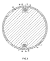
- a cross-sectional view of the rotor 26 of Fig. 2 is illustrated.
- the superconductive rotor coil 12 is disposed within slots 40 formed in the rotor core 30.
- the rotor 26 also comprises an electromagnetic shield 42 disposed around the rotor core 30.
- a vacuum envelope 44 extends around the rotor core 30 between the electromagnetic shield 42 and the rotor core 30.
- the quench detection system 16 comprises a thermally conductive copper sheet 46 formed around the superconductive rotor coil 12 and an insulation layer 48 disposed between the copper sheet 46 and the coil 12.
- the copper sheet 46 disseminates heat generated by the superconductive coil 12 when the coil 12 is driven into a resistive state, thereby reducing the temperature. This reduction in temperature increases the over-current capacity of the coil 12 and reduces the peak temperature in the event of a quench.
- the copper sheet 46 also serves to conduct heat to the temperature sensor 38.
- the copper sheet 46 may couple the heat produced as a result of the quenching to the temperature sensor 38, thereby improving the ability of the temperature sensor 38 to detect quenching.
- a copper sheet is used in the illustrated embodiment, other thermally conductive materials may be used.
- the layer of insulation 48 in the illustrated embodiment is made of a G10 or similar material.
- the temperature sensor 38 is disposed on the superconductive coil between the superconductive coil 12 and the copper sheet 46.
- the temperature sensor 38 is a resistance temperature detector (RTD) wire embedded in the insulation layer 48.
- the electrical resistance of the temperature sensor 38 varies with the temperature of the superconductive rotor coil 12.
- a platinum wire is used as the temperature sensor 38 because of its resistivity at the critical temperature of the superconductive rotor coil.
- wire of a different material may be used as the temperature sensor 38.
- Other types of temperature feedback devices may be used, such as a thermocouple.
- the temperature sensor 38 is mounted in a bifilar configuration to minimize the effect of voltages induced in the temperature sensor 38.
- the wire sensor 38 is disposed along the superconductive rotor coil 12 adjacent to the expected regions 50 of the lowest critical current in the coil 12.
- the critical current is the current beyond which the superconductive coil 12 undergoes a transition from a superconducting state to a normal resistive state.
- the region of the coil 12 that has the lowest critical current 50 is the region that would be expected to quench first in the event of a quench.
- the critical current is a function of the magnetic field distribution of the superconductive coil 12, i.e., the critical current changes with respect to both the magnitude and the direction of the magnetic field.
- the region of the lowest critical current may be determined by first computing the magnetic field distribution as a function of the critical current along the entire coil. The data obtained from the magnetic field distribution is used to calculate the critical current at each point in the coil.
- the region of the coil 12 with the lowest critical current may be determined.
- the temperature sensor 38 extends along a substantial length of the superconductive coil 12, partial quenches that occur at locations along the length of the coil 12 may be detected by the temperature sensor 38.
- the copper sheet 46 is operable to conduct heat to the temperature sensor 38 from hot spots located at a distance from the temperature sensor 48, thereby increasing the sensitivity of the temperature sensor 38.
- a method of monitoring and protecting a superconductive rotor coil from a quench condition is illustrated, and represented generally by reference numeral 52.
- the method 52 comprises providing a signal representative of superconductive coil temperature to a control system operable to control current to the superconductive coil, as represented by block 54.
- the method may also comprise processing the signal representative of the temperature of the superconductive rotor coil 12 received from the temperature sensor 38, as represented by block 56.
- the quench control system 20 is operable to receive the signal representative of the temperature of the superconductive rotor coil 12 from the telemetry 18 and determine the temperature of the superconductive rotor coil 12. As noted above, the quench control system 20 may compensate for any magneto-resistance effects experienced by the temperature sensor 38 due to the magnetic field produced by the superconductive rotor coil 12.
- the method also comprises determining if a quench condition exists based on the temperature of the superconductive rotor coil 12, as represented by block 58. If the temperature of the superconductive rotor coil 12 rises to the defined temperature, the quench control system 20 determines that quenching is occurring. If quenching is occurring, the quench control system 20 activates the dump circuit 22 to reduce the current flowing in the superconductive rotor coil 12, as represented by block 60.
- the dump circuit 22 removes power to the coil 12 and couples the coil 12 to a dump resistor in the dump circuit 22 to discharge the magnetic energy stored in the coil 12, further reducing the flow of current in the coil 12. With no current flowing through the coil 12, no resistive heating can occur in the coil 12. Thus, the superconductive coil 12 is protected from the harmful effects of quenching.
- the techniques described above provide a system and method for protecting a superconductive rotor coil 12 from quenching by using the temperature of the superconductive rotor coil as the indicator of quenching. Using the temperature of the superconductive rotor coil 12 as the indicator of quenching removes the influence of large inductive voltages produced in the rotor 26 from the quench detection process.
- the techniques described above increase the ability of the superconductive rotor coil 12 to tolerate resistive heating during quenching by providing a path for heat to flow away from the superconductive coil 12 and into the thermally conductive sheet 46 disposed proximate to the soil 12, thereby reducing the effect of quenching.
Landscapes
- Engineering & Computer Science (AREA)
- Power Engineering (AREA)
- Microelectronics & Electronic Packaging (AREA)
- Superconductive Dynamoelectric Machines (AREA)
Abstract
Description
Claims (10)
- A rotating machine (10), comprising:a superconductive coil (12) disposed within a rotor (26); anda temperature sensor (38) operable to provide a signal representative of superconductive coil temperature.
- The rotating machine (10) of claim 1, comprising a control system (20) communicatively coupled to the temperature sensor (38) and operable to reduce electric current in the superconductive coil (12) when a signal representative of a defined superconductive coil temperature is received from the temperature sensor (38).
- The rotating machine (10) of claim 2, comprising a thermally conductive sheet (46) disposed around the superconductive coil (12), wherein the temperature sensor (38) is disposed between the thermally conductive sheet (46) and the superconductive coil (12).
- The rotating machine (10) of claim 2, wherein the control system (20) is operable to compensate for magneto-resistive effects produced in the temperature sensor (38) by the magnetic field produced by the superconductive coil (12).
- The rotating machine (10) of claim 1, wherein the temperature sensor (38) is a resistance temperature detector.
- The rotating machine (10) of claim 5, wherein the resistance temperature detector (38) comprises a wire disposed adjacent to an expected region of the lowest critical current (50) in the superconductive coil (12).
- A quench monitoring and control system (14) for a superconductive coil (12), the system comprising:a temperature sensor (38) operable to provide a signal representative of superconductive coil temperature; anda control system (20) coupled to the temperature sensor (38) and operable to reduce electric current in the superconductive coil (12) when a signal representative of a defined superconductive coil temperature is received from the temperature sensor (38).
- A method of operating a rotating machine (10) having a superconductive coil (12), the method comprising:providing a signal representative of superconductive coil temperature to a control system (20) operable to control current to the superconductive coil (12); andreducing current to the superconductive coil (12) when a signal representative of a defined superconductive coil temperature is received.
- The method of claim 8, wherein reducing current to the superconductive coil (12) comprises compensating for magneto resistance effects caused by the superconductive coil (12) on a temperature sensor (38).
- The method of claim 23, wherein compensating for magneto-resistance effects comprises establishing a magnetic field strength experienced by the sensor (38) based on superconductive coil current and applying a correction to the signal representative of superconductive coil temperature based on the magnetic field strength.
Applications Claiming Priority (2)
| Application Number | Priority Date | Filing Date | Title |
|---|---|---|---|
| US813281 | 1997-03-10 | ||
| US10/813,281 US7053509B2 (en) | 2004-03-30 | 2004-03-30 | Quench monitoring and control system and method of operating same |
Publications (2)
| Publication Number | Publication Date |
|---|---|
| EP1583211A2 true EP1583211A2 (en) | 2005-10-05 |
| EP1583211A3 EP1583211A3 (en) | 2009-09-09 |
Family
ID=34887704
Family Applications (1)
| Application Number | Title | Priority Date | Filing Date |
|---|---|---|---|
| EP05250407A Withdrawn EP1583211A3 (en) | 2004-03-30 | 2005-01-26 | Superconductor quench monitoring and control system and method of operating the same |
Country Status (3)
| Country | Link |
|---|---|
| US (1) | US7053509B2 (en) |
| EP (1) | EP1583211A3 (en) |
| JP (1) | JP4733989B2 (en) |
Cited By (3)
| Publication number | Priority date | Publication date | Assignee | Title |
|---|---|---|---|---|
| EP2104198A3 (en) * | 2008-03-19 | 2011-08-17 | General Electric Company | Systems And Methods Involving Protection Of Superconducting Generators For Power Applications |
| WO2012171776A3 (en) * | 2011-06-14 | 2013-05-30 | Siemens Aktiengesellschaft | Synchronous machine with hts rotor |
| JP2013183465A (en) * | 2012-02-29 | 2013-09-12 | Kawasaki Heavy Ind Ltd | Field rotator of superconduction rotary machine |
Families Citing this family (12)
| Publication number | Priority date | Publication date | Assignee | Title |
|---|---|---|---|---|
| US7262679B2 (en) * | 2005-07-19 | 2007-08-28 | E.I. Du Pont De Nemours And Company | Rotary transformer |
| US7719400B1 (en) | 2005-08-02 | 2010-05-18 | Rtd Company | Method and apparatus for flexible temperature sensor having coiled element |
| US7630179B2 (en) * | 2005-09-22 | 2009-12-08 | Reliance Electric Technologies, Llc | Protective link for superconducting coil |
| JP4825605B2 (en) * | 2006-07-04 | 2011-11-30 | 株式会社東芝 | High temperature superconducting coil device |
| US7633192B2 (en) * | 2006-09-28 | 2009-12-15 | Siemens Energy, Inc. | Superconducting coil support structures |
| US8251579B2 (en) | 2007-07-16 | 2012-08-28 | Rtd Company | Robust stator winding temperature sensor |
| EP2458256A1 (en) * | 2010-11-30 | 2012-05-30 | Converteam Technology Ltd | Insulation for a cryogenic component |
| EP2909594A4 (en) | 2012-10-16 | 2016-05-18 | Measurement Spec Inc | ENHANCED SOFT TEMPERATURE SENSOR |
| FR3000321B1 (en) * | 2012-12-20 | 2016-07-22 | European Aeronautic Defence & Space Co Eads France | ELECTRICAL MACHINE WITH SUPERCONDUCTING COILS |
| US9240681B2 (en) | 2012-12-27 | 2016-01-19 | General Electric Company | Superconducting coil system and methods of assembling the same |
| US9112444B2 (en) * | 2013-03-14 | 2015-08-18 | Remy Technologies, L.L.C. | Electric machine including a temperature sensing system |
| US11521771B2 (en) | 2019-04-03 | 2022-12-06 | General Electric Company | System for quench protection of superconducting machines, such as a superconducting wind turbine generator |
Family Cites Families (8)
| Publication number | Priority date | Publication date | Assignee | Title |
|---|---|---|---|---|
| JPS63190313A (en) * | 1987-02-03 | 1988-08-05 | Japan Atom Energy Res Inst | Detection of normal conduction transition in superconducting magnet |
| US5047741A (en) | 1989-08-17 | 1991-09-10 | General Electric Company | Epoxy-impregnated superconductive tape coils |
| DE4124433C2 (en) * | 1990-08-20 | 2003-02-20 | Siemens Ag | Circuit arrangement with an electrical conductor and a device for detecting the temperature along the electrical conductor |
| US5548168A (en) | 1994-06-29 | 1996-08-20 | General Electric Company | Superconducting rotor for an electrical machine |
| US6420842B1 (en) | 2000-01-11 | 2002-07-16 | American Superconductor Corporation | Exciter and electronic regulator for rotating machinery |
| WO2001058005A2 (en) * | 2000-01-11 | 2001-08-09 | American Superconductor Corporation | Exciter assembly telemetry |
| JP3717792B2 (en) * | 2001-02-27 | 2005-11-16 | 住友重機械工業株式会社 | Refrigerator cooled superconducting magnet device |
| US6642682B1 (en) * | 2002-02-21 | 2003-11-04 | Active Power Inc. | Circuits and methods for preheating a rotor of a motor-generator device |
-
2004
- 2004-03-30 US US10/813,281 patent/US7053509B2/en not_active Expired - Fee Related
-
2005
- 2005-01-26 EP EP05250407A patent/EP1583211A3/en not_active Withdrawn
- 2005-01-28 JP JP2005021072A patent/JP4733989B2/en not_active Expired - Fee Related
Cited By (4)
| Publication number | Priority date | Publication date | Assignee | Title |
|---|---|---|---|---|
| EP2104198A3 (en) * | 2008-03-19 | 2011-08-17 | General Electric Company | Systems And Methods Involving Protection Of Superconducting Generators For Power Applications |
| WO2012171776A3 (en) * | 2011-06-14 | 2013-05-30 | Siemens Aktiengesellschaft | Synchronous machine with hts rotor |
| JP2013183465A (en) * | 2012-02-29 | 2013-09-12 | Kawasaki Heavy Ind Ltd | Field rotator of superconduction rotary machine |
| EP2822162A4 (en) * | 2012-02-29 | 2016-02-24 | Kawasaki Heavy Ind Ltd | SURFACE ROTOR ROTOR OF SUPERCONDUCTING ROTATING MACHINE |
Also Published As
| Publication number | Publication date |
|---|---|
| EP1583211A3 (en) | 2009-09-09 |
| JP4733989B2 (en) | 2011-07-27 |
| US20050218731A1 (en) | 2005-10-06 |
| JP2005287286A (en) | 2005-10-13 |
| US7053509B2 (en) | 2006-05-30 |
Similar Documents
| Publication | Publication Date | Title |
|---|---|---|
| US7053509B2 (en) | Quench monitoring and control system and method of operating same | |
| EP1612903B1 (en) | System and method for quench and over-current protection of superconductor | |
| JP4856393B2 (en) | System and method for quench protection of superconductors | |
| US20140055103A1 (en) | System and method for monitoring temperature inside electric machines | |
| US10984934B2 (en) | Fast inductive heaters for active quench protection of superconducting coil | |
| EP0489291B1 (en) | Superconducting magnet system with inductive quench heaters | |
| Ariyama et al. | Quench protection of YBCO coils: Co-winding detection method and limits to hot-spot temperature | |
| EP2755216B1 (en) | Superconducting coil protection method and superconducting magnet device | |
| US7477492B2 (en) | Superconducting magnet system | |
| US4978922A (en) | Superconducting sensor for quench detection in a superconductor | |
| Kim et al. | Normal zone propagation in 2-dimensional YBCO winding pack models | |
| US7630179B2 (en) | Protective link for superconducting coil | |
| US5862028A (en) | Method and apparatus for detecting quenching of a coil for a superconducting magnet | |
| Eckert et al. | Numerical treatment of the quenching process in superconducting magnet systems | |
| GB2126028A (en) | Quench detector for superconducting winding | |
| JP5057965B2 (en) | Superconducting device, energy storage device including the superconducting device, and magnetic field generating device including the superconducting device | |
| KR101759269B1 (en) | Local-insulation winding for high temperature superconducting magnets and manufacture method of the same | |
| Toriyama et al. | Quench protection of HTS magnet composed of multiple pancake-coils by forming auxiliary dump resistor loop | |
| JPH05299245A (en) | Method and device for measuring temperature of superconductor, and method and device for predicting quench of superconducting magnet | |
| JPS61230303A (en) | Protection circuit for superconductive electromagnet | |
| WO2025147419A1 (en) | Co-wound coaxial voltage sensors for quench detection in grooved, stacked-plate, no-insulation superconducting coils | |
| Eckert et al. | A computer program simulating the quench of superconducting magnet systems | |
| JPS62176Y2 (en) | ||
| JPS5933803A (en) | Sensor for detecting quenching of superconductive coil | |
| Schmidt et al. | Quench studies for the LHC corrector magnet MSBH |
Legal Events
| Date | Code | Title | Description |
|---|---|---|---|
| PUAI | Public reference made under article 153(3) epc to a published international application that has entered the european phase |
Free format text: ORIGINAL CODE: 0009012 |
|
| AK | Designated contracting states |
Kind code of ref document: A2 Designated state(s): AT BE BG CH CY CZ DE DK EE ES FI FR GB GR HU IE IS IT LI LT LU MC NL PL PT RO SE SI SK TR |
|
| AX | Request for extension of the european patent |
Extension state: AL BA HR LV MK YU |
|
| PUAL | Search report despatched |
Free format text: ORIGINAL CODE: 0009013 |
|
| AK | Designated contracting states |
Kind code of ref document: A3 Designated state(s): AT BE BG CH CY CZ DE DK EE ES FI FR GB GR HU IE IS IT LI LT LU MC NL PL PT RO SE SI SK TR |
|
| AX | Request for extension of the european patent |
Extension state: AL BA HR LV MK YU |
|
| 17P | Request for examination filed |
Effective date: 20100309 |
|
| AKX | Designation fees paid |
Designated state(s): DE FR GB IT |
|
| 17Q | First examination report despatched |
Effective date: 20100726 |
|
| STAA | Information on the status of an ep patent application or granted ep patent |
Free format text: STATUS: THE APPLICATION IS DEEMED TO BE WITHDRAWN |
|
| 18D | Application deemed to be withdrawn |
Effective date: 20140801 |