BACKGROUND OF THE INVENTION
FIELD OF THE INVENTION
The present invention relates to a leader tape, to a
magnetic tape cartridge in which the cartridge case rotatably
houses a reel with a magnetic tape wound up therearound along
with the leader tape bonded thereto, and to a magnetic recording
and reproduction method.
DESCRIPTION OF THE INVENTION
As magnetic tape cartridges used as recording media for
external memory devices for computers and others, heretofore
known are those of a type where a magnetic tape is wound up around
one or more reels rotatably housed in the cartridge case. Since
the magnetic tapes are used for data storage for computers and
others and since important information is recorded therein, the
cartridges are specifically so designed that they are free from
a trouble of tape jamming and that a magnetic tape is not carelessly
led out of them.
In a single reel-type cartridge, a leader member such
as a leader pin or a leader block is fitted to the top end of
the magnetic tape, via which the magnetic tape is led out of
the cartridge; or a leader tape is bonded thereto, which is formed
of a relatively hard plastic material and which has engage holes
formed at the top end of the tape. For the cartridge of the
type, a drive device is so constructed that the magnetic tape
therein could be loaded/unloaded (draw out/ wind up) while the
leader member or the leader tape top end is held by the holder
member on the side of a recording and reproduction device.
In the loading/unloading process as above where the
magnetic tape is drawn out toward the side of the magnetic
recording and reproduction device and its top end is wound up
around the drive reel in the device, the top end of the magnetic
tape is contacted with the tape guide and the magnetic head
disposed along the tape-running route, while not accurately
positioned relative to them, and in that condition, it is pulled
and is therefore readily damaged. Accordingly, it is desirable
that the top end of the magnetic tape is reinforced.
In addition, the reinforcement is also desirable in order
to prevent the leader block level difference occurring in the
drive reel from being embossed onto a data-recording magnetic
tape to increase the dropouts in the tape. For this, a leader
tape having a higher strength than that of a magnetic tape is
bonded to the top end of the magnetic tape (e.g., see
JP-A-2001-110169).
With the recent increase in the capacity of magnetic tape
cartridges, the recording density of magnetic tapes is increasing,
and drive makers are now toward increasing the in-plane recording
density of magnetic tapes by reducing the recording wavelength
so as to increase the recording density in the machine direction
of tapes and further by reducing the recording track width so
as to increase the recording density in the lateral direction
thereof. With the increase in the recording density, the
influence of the spacing between the magnetic layer and the
magnetic head increases, and therefore, when magnetic tapes are
deformed, then they cause dropouts and significantly increase
error rates.
The leader block mentioned above is so designed that it
may be housed in the recess formed in the core of a take-up reel,
and when housed therein, a part of the leader block forms a part
of the arc face of the core.
This is graphically illustrated. As in Fig. 4A, a leader
block 40 is fitted.into the recess 42 formed along the radial
direction of the core 41, and, for example, in this condition,
the end face 40a of the leader block 40 forms a part of the take-up
face of the core 41. As illustrated, the end face 40a of the
leader block 40 is curved like an arc in correspondence to the
outer peripheral face of the core 41, in order to smoothly wind
up the magnetic tape MT around it.
However, in such a related art tape drive, the end face
40a may protrude above the core 41, as in Fig. 4B, depending on
the dimensional accuracy of the leader block 40 that constitutes
a part of the take-up face, and it may form an unacceptable level
difference in the take-up face of the core 41.
The level difference may cause folding or deformation
of the leader tape LT, and, as in Fig. 4C, the folding and the
deformation occur similarly also in the part of the magnetic
tape MT which is wound up as the subsequent layers and which
is to be a substantial recording region (this may be referred
to as "leader block embossment"). The leader block embossment
may cause a problem in that a suitable distance between the tape
and the recording/reproducing head could not be ensured in the
process of information recording/reproduction, and it may
therefore cause recording failure and information loss.
If the time for which the tape is kept wound up around
a take-up reel is short, then the leader block embossment would
not cause the problems as above, but when the magnetic tape MT
is kept wound up around the take-up reel and left as such for
long, then the magnetic tape MT may often have a regular leader
block embossment on the surface thereof, at a pitch of nearly
the circumference length of the core 41.
Accordingly, it has become necessary to improve the leader
tape. This phenomenon is more remarkable in a system where the
line recording density is smaller. In a system where the
difference between the recording track width and the reproduction
track width is over 17 µm, tape deformation to cause track shifting
by a few µm or so may not result in the increase in dropouts,
since the recording track width is much broader than the
reproduction track width and therefore the tape may run on the
recording track even after such a little tape deformation.
However, in a magnetic recording and reproduction device where
the difference between the recording track width and the
reproduction track width is at most 16 µm, the track shifting
owing to tape deformation becomes remarkable; and in a magnetic
recording and reproduction device where the difference is at
most 10 µm, it is substantially remarkable.
SUMMARY OF THE INVENTION
An object of the invention is to provide a leader tape
not so much troubled by the increase in dropouts to be caused
by embossment of a drive reel or a leader block onto it during
long-term storage or high-temperature running in or through a
magnetic tape cartridge for magnetic recording and reproduction
devices for high-density recording at high line recording density
and high track density; and to provide a magnetic tape cartridge,
and a magnetic recording and reproduction method.
The object of the invention can be attained by the
following means:
The leader tape of the invention is designed to have a
specifically-defined surface roughness, and therefore, when it
is wound up, a suitable distance may be formed between the faces
of the wound tape. The remarkable advantages of the leader tape
of the type are that, since the pressure to it may be relieved,
a leader block and others are prevented from being embossed to
magnetic tapes; and even when the line recording density is
increased and the track width is narrowed in magnetic recording
and reproduction devices, the leader tape may effectively prevent
the increase in dropouts and error rates that may be caused by
the leader block embossment.
BRIEF DESCRIPTION OF THE DRAWINGS
Fig. 1 is a constitutional view conceptually showing a
magnetic recording and reproduction device of one embodiment
of the invention.
Fig. 2 is a perspective exploded view showing the magnetic
tape cartridge used in the magnetic recording and reproduction
device.
Fig. 3A is a perspective view of the drive reel used in
the magnetic recording and reproduction device; Fig. 3B is a
partly-enlarged cross-sectional view of Fig. 3A cut along the
IIIB-IIIB line.
Figs. 4A to 4C are explanatory views of a related art.
DETAILED DESCRIPTION OF THE INVENTION
The center line average roughness (Ra) of at least one
face of the leader tape of the invention is from 10 to 60 nm.
"Ra" as referred to herein means a value measured with
a photointerference surface roughness meter (WYKO's HD-2000)
under the condition mentioned below.
Objective lens: 50-power, intermediate lens: 0.5-power, and
detection range: 242 µm × 184 µm; and after cylindrical
correction and inclination correction, Ra is calculated.
The leader tape of the invention is used in a magnetic
recording and reproduction device in which the line recording
density is at least 100 kfci and the difference between the
recording track width and the reproduction track width is from
0 to 16 µm.
Not specifically defined, the magnetic recording and
reproduction device may be any one that comprises a magnetic
tape cartridge and a magnetic tape drive.
Not also specifically defined, the magnetic tape
cartridge may be any one in which a magnetic tape with the leader
tape of the invention bonded thereto is wound up around one or
more reels rotatably housed in the cartridge case . The invention
produces better results when applied to single reel devices.
The leader tape of the invention may be bonded to the
top end of a magnetic tape on and from which signals are recorded
and reproduced, by attaching a known splicing tape thereto in
such a manner that one end of the leader tape is butt-jointed
with the top end of the magnetic tape. The other end of the
leader tape is provided with an engaging member such as leader
pin, and this is used for fixing the leader tape to the drive
reel of a magnetic recording and reproduction device.
The magnetic recording and reproduction method of the
invention is characterized in that the magnetic tape cartridge
of the invention is used in the magnetic recording and
reproduction device where the leader tape of the invention is
used, and it enables recording and reproduction under the
condition where the line recording density of the magnetic tape
to which the leader tape is bonded is at least 100 kfci (preferably
at least 130 kfci, more preferably at least 150 kfci) and the
difference between the recording track width (preferably at most
28 µm, more preferably at most 16 µm) and the reproduction track
width (preferably at most 13 µm, more preferably at most 8 µm)
is from 0 to 16 µm (preferably from 4 to 16 µm, more preferably
from 4 to 10 µm).
The magnetic recording and reproduction method of the
invention prevents track shifting and enables stable recording
and reproduction even when the recording track width is narrow
and the difference between the recording track width and the
reproduction track width is small as in the method.
The recording and reproduction device in which recording
and reproduction is attained at the above-mentioned track width
is not specifically defined, for which are usable any known
magnetic recording and reproduction devices equipped with
recording/reproduction heads.
The magnetic head for use in the invention is preferably
an inductive head for recording, and anMR head for reproduction.
The invention is described in more detail hereinunder.
[Leader Tape]
The coating layer formed on the support essentially
comprises a dispersion of a fine inorganic powder in a binder.
The fine inorganic powder may be a non-magnetic powder or a
magnetic powder. The coating layer may be single-layered or
multi-layered. The coating layer is formed on at least one of
the face of the support that is to be in contact with a magnetic
head, or the opposite face thereto.
The object of the coating layer is for optionally giving
some additional function to the support. For example, abrasive
particles are added to the face of the support that is to be
in contact with a magnetic head so as to make the resulting tape
have a cleaning effect; conductive particles are added thereto
so as to make the resulting tape have an antistatic function;
or a magnetic substance is added thereto in order to record
magnetic signals on the resulting tape.
The coating layer may further contains a lubricant by
which the friction factor of the layer may be controlled.
Preferably, the coating layer is so designed that the same
magnetic layer as that in the data tape to be bonded to the leader
tape, or a non-magnetic tape each alone, or a double layer that
comprises such a magnetic layer formed on a non-magnetic layer
is formed on the side of the support that is to be in contact
with a magnetic head and a back layer of essentially carbon black
is formed on the opposite side thereto.
Preferably, the overall thickness of the leader tape is
from 5 to 20 µm, more preferably from 8 to 18 µm.
Regarding the thickness of the coating layer, the single
layer or a total of multiple layers is preferably from 0.1 to
5.0 µm, more preferably from 0.5 to 3.0 µm. Also preferably,
the thickness of the support is from 3 to 17 µm, more preferably
from 6 to 17 µm.
The center line average roughness (Ra) of at least one
surface of the leader tape is from 10 to 60 nm, preferably from
15 to 45 µm. This produces a cushion effect when the tape is
wound up around a reel, and therefore prevents leader block
embossment to the tape. The surface roughness Ra of the leader
tape may be the same or may differ between the back face and
the front face thereof. The surface roughness may be controlled
in various methods. For example, the roughness of the support,
the thickness of the coating layer, the particle size of the
inorganic particles to be sued in the coating layer and the
calendering condition may be varied. When the surface roughness
of the leader tape is controlled by the roughness of the support,
then the roughness of the support may be from 5 to 80 nm, preferably
from 10 to 65 nm. The inorganic powder to be in the coating
layermayhave ameanparticle size of from 0.02 to 1 µm, preferably
from 0.05 to 0.6 µm. Its shape maybe any of granular, needle-like,
tabular or cubic ones.
Preferably, the surface resistivity of the leader tape
is at most 1010 Ω/sq, more preferably at most 109 Ω/sq. Thus
controlled, the leader tape is prevented frombeing statistically
charged and is prevented from being damaged by static charges
of magnetic heads, whereby its reliability is increased. In
addition, the strength of the leader tape is basically higher
than that of the magnetic tape which is bonded to the leader
tape, and when the magnetic tape cartridge having therein the
two tapes bonded to each other is driven in a magnetic recording
and reproduction device in which the tapes are repeatedly
loaded/unloaded, then the durability of the leader tape is kept
high.
For controlling the surface resistivity of the leader
tape to fall within the predetermined range, for example, a
conductive powder such as carbon black may be added to at least
one layer of the lower layer, the upper layer and the back layer
of the tape. For example, from 1 to 20 parts by weight of carbon
black may be added to 100 parts by weight of the binder in each
layer.
Preferably, the leader tape is a magnetic tape that
comprises a non-magnetic layer containing an inorganic powder
and a binder as the lower layer and a magnetic layer containing
a ferromagnetic powder and a binder as the upper layer, and has
a back layer formed on the opposite side thereto.
The leader tape that is the magnetic tape as above is
described in detail hereinunder.
(Magnetic Layer)
<Binder in Magnetic Layer and Non-Magnetic Layer>
The binder to be used in the magnetic layer and the
non-magnetic layer may be any of known thermoplastic resins,
thermosetting resins, reactive resins and their mixtures. The
thermoplastic resin may have a glass transition point falling
between -100 and 150°C, a number-average molecular weight falling
between 1000 and 200000, preferably between 10000 and 100000,
and a degree of polymerization falling between about 50 and 1000
or so.
Examples of the resin of the type are polymers or
copolymers comprising constitutive units of vinyl chloride,
vinyl acetate, vinyl alcohol, maleic acid, acrylic acid, acrylate,
vinylidene chloride, acrylonitrile, methacrylic acid,
methacrylate, styrene, butadiene, ethylene, vinyl butyral,
vinyl acetal, vinyl ether and the like; and polyurethane resins,
and various rubber-type resins. The thermosetting resin and
the reactive resin include, for example, phenolic resins, epoxy
resins, polyurethane-curable resins, urea resins, melamine
resins, alkyd resins, acrylic reactive resins, formaldehyde
resins, silicone resins, epoxy-polyamide resins, mixtures of
polyester resins and isocyanate prepolymers, mixtures of
polyester-polyols and polyisocyanates, and mixtures of
polyurethanes and polyisocyanates. These resins are described
in detail in Plastic Handbook (published by Asakura Shoten).
In addition, any known electron ray-curable resin may be used
in each layer. Its examples and its production methods are
described in JP-A 62-256219.
The above-mentioned resins may be used herein either
singly or as combined. Preferably, at least one selected from
polyvinyl chloride resins, vinyl chloride-vinyl acetate
copolymers, vinyl chloride-vinyl acetate-vinyl alcohol
copolymers and vinyl chloride-vinyl acetate-maleic anhydride
copolymers is combined with a polyurethane resin and a
polyisocyanate for use in the invention.
The polyurethane resin may have any known structure of
polyester-polyurethane, polyether-polyurethane,
polyether-polyester-polyurethane,
polycarbonate-polyurethane,
polyester-polycarbonate-polyurethane, and
polycaprolactone-polyurethane. Optionally but preferably,
all these binders have at least one polar group selected from
COOM, SO3M, OSO3M, P=O(OM)2, O-P=O(OM)2 (in these, M represents
a hydrogen atom or an alkali metal base), OH, N (R)2, N+(R)3 (where
R represents a hydrocarbon group), epoxy group, SN and CN,
introduced thereinto through copolymerization or addition
reaction, in order that the binders may realize further better
dispersibility and durability. The amount of the polar group
in the binders may be from 10-1 to 10-8 mol/g, preferably from
10-2 to 10-6 mol/g.
Preferably, the number of the hydroxyl groups to be in
the polyurethane resin is from 3 to 20 in one molecule, more
preferably from 4 or 5 in one molecule. If the number is smaller
than 3 in one molecule, then the reactivity of the resin with
a polyisocyanate curing agent may lower and therefore the film
strength and the durability may lower. If, however, the number
is larger than 20, then the solubility and the dispersibility
in solvent of the resin may lower. For controlling the content
of the hydroxyl groups in the polyurethane resin, a compound
having at least three functional hydroxyl groups may be used
in producing the polyurethane resin. Concretely, there are
mentioned trimethylolethane, trimethylolpropane, trimellitic
anhydride, glycerin, pentaerythritol, hexanetriol; as well as
branched polyesters and polyether-esters having 3 or more
functional hydroxyl groups that are obtained from a dibasic
starting from a polyester-polyol described in JP-B 6-64726 and
the compound serving as a glycol component. Preferred for use
herein are tri-functional compounds. Tetra- or more
multi-functional compounds may readily gel in the reaction step.
The polyisocyanates usable herein are, for example,
isocyanates such as tolylene diisocyanate,
4,4'-diphenylmethane diisocyanate (MDI), hexamethylene
diisocyanate, xylylene diisocyanate,
naphthylene-1,5-diisocyanate, o-toluidine diisocyanate,
isophorone diisocyanate, triphenylmethane triisocyanate;
products of these isocyanates with polyalcohols; and
polyisocyanates produced through condensation of these
isocyanates.
The amount of the binder to be in the magnetic layer and
the non-magnetic layer may be generally from 5 to 50 % by weight,
preferably from 10 to 30 % by weight of the ferromagnetic powder
in the magnetic layer or of the non-magnetic inorganic powder
in the non-magnetic layer. When a vinyl chloride-based rein
is used, its amount may be from 5 to 30 % by weight and when
a polyurethane resin is used, its amount may be from 2 to 20 %
by weight; and the amount of the polyisocyanate to be combined
with these is preferably from 2 to 20 % by weight. For example,
however, when head corrosion may occur owing to minor
dechlorination, a combination of only polyurethane and
isocyanate may be used.
In the magnetic tape of the type, the amount of the binder,
the proportion of the vinyl chloride-based resin in the binder,
the amount of the polyurethane resin, the polyisocyanate resin
and other resins, the molecular weight and the polar group content
of the resins constituting the magnetic layer, as well as various
physical properties of the resins mentioned above may be
optionallyvariedbetween the non-magnetic layer and the magnetic
layer, and they are rather optimized in the respective layers.
For this, employable are any known techniques relating to
multi-layered magnetic layers. For example, when the binder
amount is varied in each layer, it is effective to increase the
binder amount in the magnetic layer so as to reduce the surface
abrasion of the magnetic layer. In order to improve the head
touch of the tape to heads, the binder amount in the non-magnetic
layer may be increased so as to soften the tape.
<Ferromagnetic Powder>
The ferromagnetic powder to be used in the magnetic layer
ispreferablyaferromagnetic alloy powder comprising a principal
component of α-Fe. The ferromagnetic powder may contain any
other atoms such as Al, Si, S, Sc, Ca, Ti, V, Cr, Cu, Y, Mo,
Rh, Pd, Ag, Sn, Sb, Te, Ba, Ta, W, Re, Au, Hg, Pb, Bi, La, Ce,
Pr, Nd, P, Co, Mn, Zn, Ni, Sr and B, in addition to the predetermined
atom. In particular, the powder preferably contains at least
one of Al, Si, Ca, Y, Ba, La, Nd, Co, Ni and B, in addition to
α-Fe, more preferably at least one of Co, Y and Al.
The ferromagnetic alloy powder may contain a small amount
of a hydroxide or an oxide. The ferromagnetic alloy powder for
use herein may be any one produced according to any known method.
For producing it, for example, the following methods may be
mentioned: A method of reducing a composite organic acid salt
(principally oxalate) with a reducing vapor such as hydrogen;
a method of reducing iron oxide with a reducing vapor such as
hydrogen to obtain Fe or Fe-Co particles; a method of pyrolyzing
a metal carbonyl compound; a method of adding a reducing agent
such as sodium borohydride, hypophosphite or hydrazine to an
aqueous solution of a ferromagnetic metal so as to reduce the
metal; a method of vaporizing a metal in a low-pressure inert
gas to obtain a fine powder of the metal. Thus obtained, the
ferromagnetic alloy powder may be subjected to known slow
oxidation, for example, according to a method of dipping it in
an organic solvent and then drying it; or a method of dipping
it in an organic solvent, then introducing oxygen-containing
gas into it so as to form an oxide film on the surface of the
particles and thereafter drying the particles; or a method of
forming an oxide film on the surface of the particles by
controlling the partial pressure of the oxygen gas and the inert
gas applied thereto, not using an organic solvent. The
ferromagnetic alloy powder thus processed in any of these methods
may be used herein.
A hexagonal-system ferrite powder may also be used for
the ferromagnetic powder to be in the magnetic layer. The
hexagonal-system ferrite includes, for example, barium ferrite,
strontium ferrite, lead ferrite, calcium ferrite, and their
substituted derivatives such as Co-substituted derivatives.
Concretely, there are mentioned magnetoplumbite-type barium
ferrite and strontium ferrite, spinel-coated
magnetoplumbite-type ferrite, partially spinel
phase-containing magnetoplumbite-type barium ferrite and
strontium ferrite. They may contain any other atoms such as
Al, Si, S, Sc, Ti, V, Cr, Cu, Y, Mo, Rh, Pd, Ag, Sn, Sb, Te,
Ba, Ta, W, Re, Au, Hg, Pb, Bi, La, Ce, Pr, Nd, P, Co, Mn, Zn,
Ni, Sr, B, Ge and Nb, in addition to the predetermined atoms.
In general, substances with elements such as Co-Ti, Co-Ti-Zr,
Co-Ti-Zn, Ni-Ti-Zn, Nb-Zn-Co, Sb-Zn-Co or Nb-Zn added thereto
may be used.
(Non-Magnetic Layer)
The inorganic powder to be sued in the non-magnetic layer
is a non-magnetic powder and may be selected, for example, from
inorganic compounds such as metal oxides, metal carbonates, metal
sulfates, metal nitrides, metal carbides, metal sulfides.
Carbon black may be added to the non-magnetic layer so as to
attain known effects of reducing the surface resistivity Rs,
reducing the light transmittance and obtaining a desired
micro-Vickers hardness. When carbon black is added to the lower
layer, then the layer may be effective for storing lubricant.
Regarding its type, carbon black usable herein may be any of
furnace black for rubber, thermal black for rubber, black for
color, and acetylene black. Depending on the desired effect
thereof, carbon black to be in the lower layer must optimize
the characteristics mentioned below. When combined in the layer,
carbon black may exhibit its effect. In addition, the
non-magnetic layer may contain an organic powder depending on
its object. Known techniques relating to the magnetic layer
may apply to the lubricant, the dispersant, the additive, the
solvent and the dispersion method in the non-magnetic layer.
[Additive]
The additives that may be in the magnetic layer and the
non-magnetic layer may be those having a head-cleaning effect,
a lubricating effect, an antistatic effect, a dispersing effect
and a plasticizing effect. Concretely, those described in
WO98/35345 may be used herein.
For the lubricant, for example, herein usable are
monobasic fatty acids having from 10 to 24 carbon atoms, and
their metal salts (e.g., with Li, Na, K, Cu); monofatty acid
esters, difatty acid esters or trifatty acid esters of monobasic
fatty acids having from 10 to 24 carbon atoms and at least any
one of mono, di, tri, tetra, penta or hexa-alcohols having from
2 to 12 carbon atoms; fatty acid esters of monoalkyl ethers of
alkylene oxide polymers; and fatty acid amides having from 8
to 22 carbon atoms. The fatty acids and alcohols may contain
unsaturated bond and may be branched.
Specific examples of the fatty acids are capric acid,
caprylic acid, lauric acid, myristic acid, palmitic acid, stearic
acid, behenic acid, oleic acid, elaidic acid, linolic acid,
linolenic acid, isostearic acid. The esters include butyl
stearate, octyl stearate, amyl stearate, isooctyl stearate,
butyl myristate, octyl myristate, butoxyethyl stearate,
butoxydiethyl stearate, 2-ethylhexyl stearate, 2-octyldodecyl
palmitate, 2-hexyldodecyl palmitate, isohexadecyl stearate,
oleyloleate, dodecylstearate,tridecylstearate,oleylerucate,
neopentylglycol didecanoate, ethylene glycol dioleate.
(Back Layer)
Preferably, the back layer contains carbon black and an
inorganic powder. Regarding the binder and various additives
to the back layer, referred to are those mentioned hereinabove
for the magnetic layer and the non-magnetic layer. The thickness
of the back layer is preferably from 0 .1 to 1. 0 µm, more preferably
from 0.4 to 0.6 µm.
(Support)
The support for the magnetic tape is preferably a
non-magnetic flexible support. For this, usable are any known
films of polyesters such as polyethylene terephthalate,
polyethylene naphthalate; as well as polyolefins, cellulose
triacetate, polycarbonates, aromatic or aliphatic polyamides,
polyimides, polyamidimides, polysulfones, polyaramids, and
polybenzoxazole. Of those, preferred are polyethylene
terephthalate films and polyimide films. The support may be
previously processed for corona discharge treatment, plasma
treatment, adhesiveness improvement treatment, thermal
treatment or dust removal treatment.
Preferably, the support has an elastic modulus in the
machine direction of from 3.5 to 20 GPa, and an elastic modulus
in the cross direction of from 3.5 to 20 GPa. More preferably,
the elastic modulus of the support is from 4 to 15 in both the
machine direction and the cross direction.
(Production Method)
The magnetic layer and the non-magnetic layermaybe formed
by dissolving or dispersing the above-mentioned components in
a solvent to prepare coating compositions for these, and applying
the compositions in order on a support (web). The method may
be either a wet-on-wet system where the magnetic layer is formed
while the underlying non-magnetic layer is still wet, or a
wet-on-dry system where the magnetic layer is formed after the
underlying non-magnetic layer is dried. Thus coated and dried,
the web is suitably oriented, calendered and slit.
[Data-Recording Magnetic Tape]
The data-recording magnetic tape for use herein comprises
a magnetic layer formed on a non-magnetic support, and optionally
has a back layer. One preferred embodiment of the tape comprises
a non-magnetic lower layer and a magnetic upper layer formed
on a support having a thickness of from 2 to 9 µm, and has a
back layer formed on the opposite side thereto. The constitutive
elements of the magnetic tape are suitable to high-density
recording, and the magnetic tapes described in JP-A 2001-250219
and 2002-251710 are preferred examples for use herein.
[Magnetic Tape-Cartridge]
Themagnetic tape cartridge of the invention is so designed
that a magnetic tape is wound up around one ormore reels rotatably
housed in the cartridge case, and this is characterized in that
the leader tape that is bonded to the top end of the magnetic
tape and is let out toward a magnetic recording and reproduction
device while leading the magnetic tape is the leader tape of
the invention.
[Magnetic Recording and Reproduction Device, and Magnetic
Recording and Reproduction Method]
The leader tape of the invention exhibits its effect when
used in a magnetic recording and reproduction device where the
line recording density is at least 100 kfci and the difference
between the recording track width and the reproduction track
width is from 0 to 16 µm, and its effect is more remarkable when
it is used in a magnetic recording and reproduction device where
the difference between the recording track width and the
reproduction track width is at most 10 µm.
Preferably, the thickness of the leader tape is at most
5 times that of the magnetic tape, more preferably at most 3
times, even more preferably at most 2 times.
Also preferably, the length of the leader tape is not
shorter than the length corresponding to at least 3 windings
of the drive reel in the magnetic recording and reproduction
device, plus the tape running route length from the mouth of
the cartridge case to the drive reel.
One embodiment of the magnetic recording and reproduction
device and the magnetic recording and reproduction method of
the invention is described in detail with reference to the
drawings attached hereto. Of the drawings that are referred
to herein, Fig. 1 is a constitutional view conceptually showing
one embodiment of the recording and reproduction device of the
invention; Fig. 2 is a perspective exploded view showing the
magnetic tape cartridge used in the magnetic recording and
reproduction device; Fig. 3A is a perspective view of the drive
reel (take-up reel) used in the magnetic recording and
reproduction device; Fig. 3B is a partly-enlarged
cross-sectional view of Fig. 3A cut along the IIIB-IIIB line.
Themagnetic recording and reproduction device of this embodiment
comprises a magnetic tape cartridge with a magnetic tape wound
up around one cartridge reel (let-off reel) and a magnetic tape
drive (tape drive) loaded with the magnetic tape cartridge, and
this is used in the magnetic recording and reproduction method
described hereinunder.
As in Fig. 1, the magnetic recording and reproduction
device 1 comprises a magnetic tape cartridge 10 and a magnetic
tape drive 20. In the magnetic recording and reproduction device
1 of the type, the magnetic tape MT wound up in the magnetic
tape cartridge 10 is let off and taken by the drive reel of the
magnetic tape drive 20 that serves as a tape receiver, or the
magnetic tape MT thus wound up around the drive reel 20 is unwound
toward the cartridge reel (let-off reel) 11, whereby information
is recorded on the magnetic tape MT or the information thus
recorded on the magnetic tape MT is reproduced.
As in Fig. 2, the magnetic tape cartridge 10 satisfies
the LTO Standard, and this has a cartridge case 2 divided into
a lower half 2B and an upper half 2A. Inside it, the cartridge
case 2 houses a single cartridge reel 11 around which a magnetic
tape MT is wound up; a reel lock and a compression coil spring
5 for keeping the rotation of the cartridge reel 11 locked; a
release pad 6 for releasing the locked condition of the cartridge
reel 11; a slide door 2D for opening and closing the magnetic
tape let-off mouth 2C formed on one face of the cartridge case
2 to extend to both the lower half 2B and the upper half 2A;
a twisted coil spring 7 for forcedly pushing the slide door 2D
toward the closing position of the magnetic tape let-off mouth
2C; amiserasure preventing claw 8; and a leader pin rack 9 formed
near the magnetic tape let-off mouth 2C. A leader tape LT is
bonded to the top end of the magnetic tape MT. The magnetic
tape MT in Fig. 2 is the leader tape LT.
The magnetic tape cartridge 10 is loaded in the magnetic
tape drive 20, as in Fig. 1, and the leader tape LT is let out
by the leader block 31 which will be described hereinunder, and
the leader block 31 is fitted into the recess 23 formed in the
core 22 of the drive reel 21 in the magnetic tape drive 20.
Accordingly, the leader tape TL from the magnetic tape cartridge
10 may be thereby wound up around the core 22 of the drive reel
21.
The leader tape LT and the magnetic tape MT used in the
magnetic tape cartridge 10 of this embodiment are described in
detail.
The leader tape LT is formed long, and in this embodiment,
its length is enough to correspond to at least 3 windings around
the core 22 of the drive reel 21 in the magnetic tape drive 20.
The leader tape LT preferably has a length of from 0.5 to 5.0
m, more preferably 0.9 m.
Next described is the magnetic tape drive 20.
The magnetic tape drive 20 comprises a spindle 24, a
spindle drive unit 25 for driving the spindle 24, a magnetic
head H, a drive reel 21, a take-up reel drive unit 26 for driving
the drive reel 21, and a control unit 27, as in Fig. 1.
In addition, the magnetic tape drive 20 is provided with
a leader block 31 capable of engaging with the leader pin (see
Fig. 2) disposed at the top end of the leader tape LT from the
magnetic tape cartridge 10, and the leader block 31 is moved
toward the magnetic tape cartridge 10 by a lead-off mechanism
(not shown) including a lead-off guide 32 or the like.
When data are recorded/reproduced on/from the magnetic
tape MT, the spindle drive unit 25 and the take-up reel drive
unit 26 act to rotate and drive the spindle 24 and the drive
reel 21, whereby the magnetic tape MT is moved.
The drive reel 21 is so designed that the upper face of
the lower flange 21a has radial grooves 21b formed at regular
intervals, as in Figs. 3A and 3B. The grooves 21b function as
discharge paths for discharging the air that may enter the drive
reel 21 while the magnetic tape MT is wound up around it.
The action of the magnetic tape drive 20 is described.
When the magnetic tape cartridge 10 is set in the magnetic
tape drive 20 as in Fig. 1, then the lead-off guide 32 (see Fig.
2) acts to lead out the leader pin 30 and move it to the drive
reel 21 via the magnetic head H, and the leader block 31 is thereby
fitted into the recess 23 of the core 22 of the drive reel 21.
The recess 23 is provided with an anchor part (not shown) that
engages with the leader block 31 to thereby prevent the leader
block 31 from jumping out of the recess 23.
With that, the spindle drive unit 25 and the take-up reel
drive unit 26 are driven while controlled by the control unit
27, and the spindle 24 and the drive reel 21 are rotated in the
same direction so that the leader tape LT and the magnetic tape
MT are moved toward the drive reel 21 from the cartridge reel
11. Accordingly, the leader tape LT is wound up around the drive
reel 21, and then the magnetic tape MT is wound up around the
drive reel 21, whereupon information is recorded on the magnetic
tape MT or the information recorded on the magnetic tape MT is
reproduced by the action of the magnetic head H.
When the magnetic tape MT is rewound around the cartridge
reel 11, the spindle 24 and the drive reel 21 are rotated and
driven in the direction opposite to the above, whereby the
magnetic tape MT is moved toward the cartridge reel 11. Also
in the rewinding operation, information recording on the magnetic
tape MT or information reproduction from the magnetic tape MT
may be attained by the magnetic head H.
In the magnetic recording and reproduction device 1 of
the type, the magnetic tape MT is generally kept wound in the
magnetic cartridge 10 in many cases, but in some use embodiment,
it may be kept wound up around the drive reel 21 in the magnetic
tape drive 20 for a long period of time. In some such use
embodiment, the usefulness of preventing leader block embossment
is extremely great, and the leader tape and the magnetic tape
cartridge employed in the magnetic recording and reproduction
device 1 of this embodiment and the magnetic recording and
reproduction method for the device 1 are favorable for the case.
Specifically, when the magnetic tape MT is wound up around the
drive reel 21 of the magnetic tape drive 20 from the magnetic
tape cartridge 10, the leader block 31 that acts to lead the
magnetic tape MT out of the magnetic tape cartridge 10 is fitted
into the core 22 of the drive reel 21, but depending on the
dimensional accuracy of the leader block 31, the leader block
31 may protrude (as level difference) from the edge face of the
core 22. In such a case, when a related art leader tape is wound
up around the drive reel 21, then the level difference may be
embossed to the magnetic tape MT and the distance between the
magnetic head and the magnetic layer may be enlarged, therefore
causing some problems of recording failure and information loss
in the magnetic tape MT.
Contrary to this, in the magnetic recording and
reproduction method of the invention, the level difference can
be well absorbed by the leader tape LT, and even when the magnetic
recording and reproduction device 1 is used, in which the line
recording density is at least 100 kfci and the difference between
the recording track width and the reproduction track width is
from 0 to 16 µm, the method of the invention enjoys the advantage
in that it can evade the problems of recording failure and
information loss in the magnetic tape MT.
EXAMPLES
The invention is described in detail with reference to
the following Examples, to which, however, the invention should
not be limited.
[Example 1]
In the Examples, "part" is by weight.
| Formation of Leader Tape: |
| <Preparation of Coating Compositions> |
| Coating Composition for upper layer: |
| Ferromagnetic metal powder | 100 parts |
| coercive force Hc: 191 kA/m (2400 Oe) |
| specific surface area by BET method: 62 m2/g |
| crystallite size: 110 angstroms |
| saturation magnetization σs: 117 A·m2/kg |
| mean major axis length: 45 nm |
| mean acicular ratio: 5 |
| pH: 9.3 |
| Co/Fe: 25 atm.% |
| Al/Fe: 7 atm. % |
| Y/Fe: 12 atm.% |
| Vinyl chloride-based copolymer (Nippon Zeon's MR-100) | 5 parts |
| (-SO3Na content: 5 × 10⁻⁶ eq/g, degree of polymerization: 350), epoxy content: 3.5 mas.% as monomer unit) |
| Polyester-polyurethane resin | 12 parts |
| (neopentylglycol/caprolactone polyol/MDI = 0.9/2.6/1 by weight, -SO3Na content: 1 × 10⁻⁴ eq/g) |
| α-alumina (mean particle size: 0.3 µm) | 10 parts |
| Carbon black (mean particle size: 0.10 µm) | 1 part |
| Butyl stearate | 1.5 parts |
| Stearic acid | 0.5 parts |
| Methyl ethyl ketone | 150 parts |
| Cyclohexanone | 50 parts |
| Toluene | 40 parts |
| Coating Composition for under layer: |
| Non-magnetic powder, acicular α-iron oxide | 80 parts |
| specific surface area by BET method: 58 m2/g |
| mean major axis length: 0.15 µm |
| acicular ratio: 7.5 |
| Carbon black | 20 parts |
| mean primary particle size: 16 nm |
| DBP oil absorption: 80 ml/100 g |
| pH: 8.0 |
| specific surface area by BET method: 250 m2/g |
| Vinyl chloride-based polymer | 12 parts |
| Nippon Zeon's MR-100 |
| Polyester-polyurethane resin | 5 parts |
| (neopentylglycol/caprolactone polyol/MDI = 0.9/2.6/1 by weight, -SO3Na content: 1 × 10⁻⁴ eq/g) |
| Butyl stearate | 1.06 parts |
| Stearic acid | 1.18 parts |
| Methyl ethyl ketone | 150 parts |
| Cyclohexanone | 50 parts |
| Toluene | 40 parts |
The constitutive components of the upper layer coating composition and those of the lower layer coating composition were separately kneaded in a continuous kneader and then dispersed by the use of a sand mill. 5 parts of polyisocyanate (Nippon Polyurethane's Coronate L) was added to each of the resulting dispersions, and 40 parts of methyl ethyl ketone was added to each of them. The dispersions were filtered through a filter membrane having a mean pore size of 1 µm, and the upper layer coating composition and the lower layer coating composition were thus obtained.
| Coating Composition for back layer formation: |
| Particulate carbon black | 100 parts |
| (Cabot's BP-800, mean particle size: 17 nm) |
| Coarse carbon black | 10 parts |
| (Carncalp's thermal black, mean particle size: 270 nm) |
| α-alumina | 5 parts |
| (hard inorganic powder) (mean particle size: 200 nm, Mohs' hardness: 9) |
| Nitrocellulose resin | 140 parts |
| Polyurethane resin | 15 parts |
| Polyester resin |
| | 5 parts |
| Dispersant: copper oleate | 5 parts |
| Copper phthalocyanine |
| | 5 parts |
| Barium sulfate (precipitating) | 5 parts |
| (BF-1, mean particle size: 50 nm, Mohs' hardness: 3, by Sakai Kagaku Kogyo) |
| Methyl ethyl ketone | 1200 parts |
| Butyl acetate | 300 parts |
| Toluene | 600 parts |
The constitutive components of the back layer coating
composition were kneaded in a continuous kneader and then
dispersed by the use of a sand mill. 40 parts of polyisocyanate
(Nippon Polyurethane' s Coronate L) and 1000 parts of methyl ethyl
ketone were added to the resulting dispersion, and this was
filtered through a filter membrane having a mean pore size of
1 µm to prepare a back layer coating composition.
Formation of Leader Tape:
The upper layer coating composition and the lower layer
coating composition thus obtained in the above were applied at
the same time to a long-size polyethylene terephthalate (PET)
support (thickness: 14.5 µm, Young's modulus in MD direction:
500kg/mm2 (4.9 GPa), Young's modulus in TD direction: 500 kg/mm2
(4.9 GPa), center line average roughness Ra of the upper
layer-coated face: 35 nm, Ra of the back layer-coated face: 36
nm) in a mode of simultaneous coating to form an upper layer
and a lower layer so that they could have a dry thickness of
0.1 µm and 1.4 µm, respectively. Next, while the upper layer
was still wet, this was oriented by the use of a cobalt magnet
having a magnetic force of 300 mT and a solenoid having a magnetic
force of 150 mT. Next, this was dried, and the upper layer was
thus formed.
Next, on the other face of the support (opposite side
to the upper layer), the back layer coating composition was
applied to form a back layer so that it could have a dry thickness
of 0.5 µm. Then, this was dried and the back layer was formed.
Accordingly, a leader tape roll was thus obtained, having the
upper layer on one face of the support and having the back layer
on the other face thereof.
Further, after heat-treated, the roll was calendered by
passing it through a 7-stage calendering machine (temperature:
90°C, linear pressure: 300 kg/cm (294 kN/m)) that comprises a
heating metal roll and an elastic roll formed by covering a core
metal with a thermosetting resin.
The resulting roll was further heated at 50°C for 48 hours.
Next, this was cut into pieces having a width of 1/2 inches to
obtain leader tapes. The overall thickness of the leader tape
was 16.5 µm, and Ra of the magnetic face thereof was 25 nm and
Ra of the back face thereof was 30 nm.
[Data Recording Magnetic Tape]
The upper and lower layer coating compositions and the
back layer coating composition used for the leader tape as above
were applied to a polyethylene naphthalate (PEN) support having
Ra of the face thereof to be coated with a magnetic layer of
3 nm and having a thickness of 5.2 µm. Concretely, the coating
compositions were applied to the support at the same time in
a mode of simultaneous coating to form a non-magnetic lower layer
having a thickness of 1.0 µm and a magnetic upper layer having
a thickness of 0.1 µm. Then, this was subjected to the same
magnetic field orientation as that for the above-mentioned leader
tape.
Next, a back layer was formed on it so as to have a dry
thickness of 0.5 µm. Also like the leader tape as above, this
was worked into data recording magnetic tapes having a width
of 1/2 inches.
[Construction of Magnetic Tape Cartridge]
The 1/2-inch wide magnetic tape obtained in the above
was used as a leader tape, and this was connected to the data
recording magnetic tape to construct a magnetic tape cartridge.
In this, 830 m of the magnetic tape was wound up.
[Example 2]
In the formation of a leader tape as in Example 1, herein
used was a PET support of which one face to be coated with
multi-layers had a center line average roughness Ra of 10 nm.
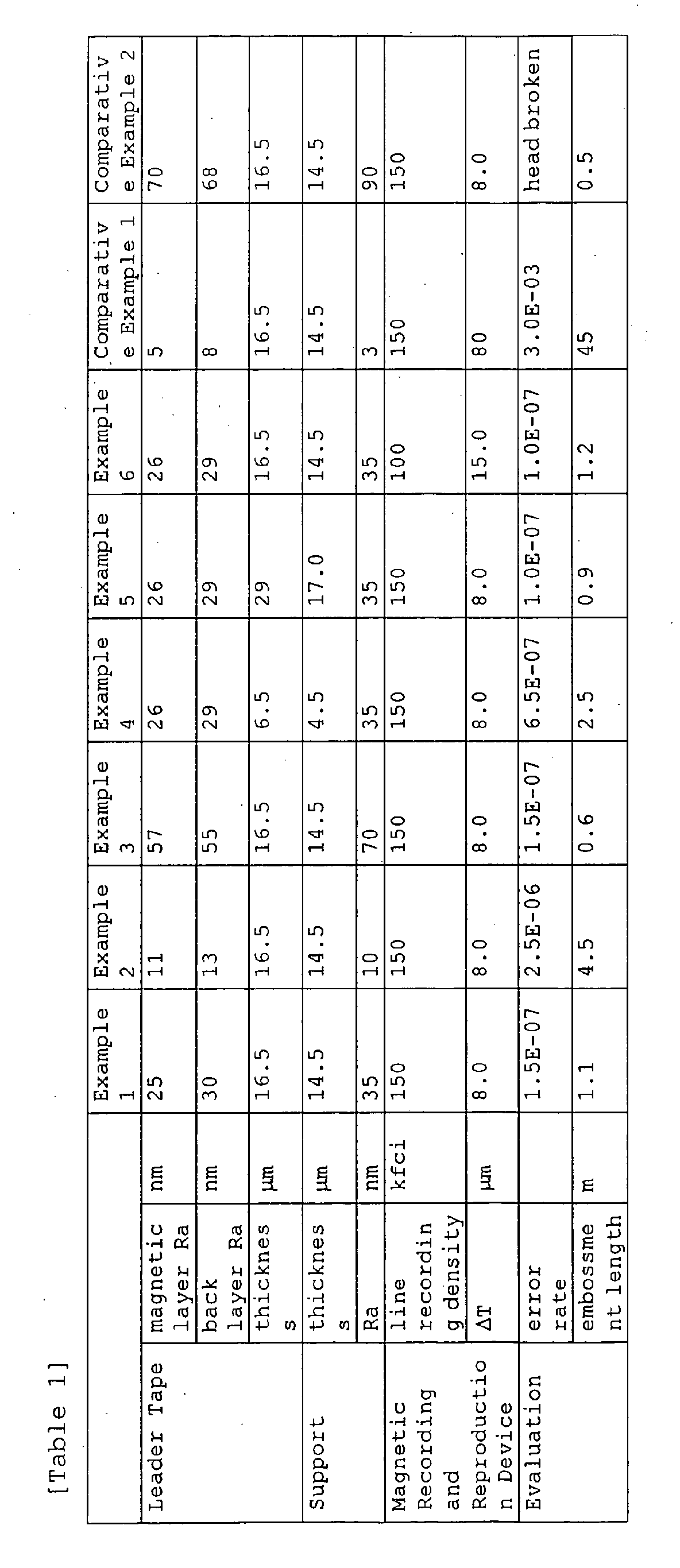
[Examples 3 to 6]
In the formation of a leader tape as in Example 1, the
thickness of the PET support and Ra of the support were varied
as in Table 1, and the others were the same as in Example 1 to
construct magnetic tape cartridges of the invention.
[Comparative Example 1]
In the formation of a leader tape as in Example 1, Ra
of the support was controlled like in the Example.
[Comparative Example 2]
In the formation of a leader tape as in Example 1, only
the upper layer having a thickness of 1.5 µm was formed in a
mode of single-layer formation, and the others were the same
as in Example 1 to construct a magnetic tape cartridge.
[Evaluation of Magnetic Tape Cartridge]
Thus obtained, the magnetic tape cartridge were tested
under the test condition mentioned below and evaluated.
(Leader block embossment Test)
The magnetic tape cartridge was set in an LTO-modified
drive, in which a signal of a line recording density of 150 kfci
was recorded on the recording tape at a recording track width
of 10 µm and a reproduction track width of 4.5 µm, and all its
length was wound up around the drive reel under a tension of
0.8 N. In that condition, every drive stored at 50°C for 12
hours. After the storage, the tape was reproduced, and the error
rate at the tape start end was determined and the length of the
tape having leader block embossment thereto (embossment length:
distance from the leader tape bonding part) was visually measured.
The error rate expression "1.5E-07" means "1.5 × 10⁻⁷" (the same
shall apply to the others).
In Example 6, the head design was varied, and the recording
track width, the reproduction track width and the line recording
density were changed as in Table 1 . In that condition, the tape
was subjected to the same embossment test. ΔT indicates the
difference between the recording track width and the reproduction
track width.
It is understood that in the Examples of the invention
where the magnetic recording and reproduction device used is
so controlled that the line recoding density is 150 kfci and
Δt is 8 . 0 µm, the error rate is smaller and the embossment length
is shorter than those in the Comparative Examples.
This application is based on Japanese Patent application
JP 2004-091822, filed March 26, 2004, the entire content of
which is hereby incorporated by reference. This claim for
priority benefit is being filed concurrently with the filing
of this application.
List of reference numbers:
FIG. 1:
- 1
- MAGNETIC RECORDING AND REPRODUCTION DEVICE
- 10
- MAGNETIC TAPE CARTRIDGE
- 24
- SPINDLE
- 20
- MAGNETIC TAPE DRIVE
- 11
- CARTRIDGE REEL
- H
- MAGNETIC HEAD
- MT
- MAGNETIC TAPE
- 31
- LEADER BLOCK
- 21
- DRIVE REEL
- 25
- SPINDLE DRIVE UNIT
- 27
- CONTROL UNIT
- 26
- TAKE-UP REEL DRIVE UNIT
FIG. 2:
- 10
- MAGNETIC TAPE CARTRIDGE
- 2
- CARTRIDGE CASE
- 2A
- UPPER HALF
- 2B
- LOWER HALF
- 11
- CARTRIDGE REEL
- MT
- MAGNETIC TAPE (LT LEADER TAPE)
- 30
- LEADER PIN
- 31
- LEADER BLOCK
FIGS. 3A AND 3B:
- 21
- DRIVE REEL (TAKE-UP REEL)
- 21A
- FLANGE
- 21B
- GROOVE
- 21
- DRIVE REEL (TAKE-UP REEL)
- 21B
- GROOVE
- 21A
- FLANGE
FIGS. 4A TO 4C:
- 41
- CORE
- 40A
- END FACE
- LT
- LEADER TAPE
- 41
- CORE
- 40A
- END FACE
- LT
- LEADER TAPE
- LT
- LEADER TAPE
- 41
- CORE
- MT
- MAGNETIC TAPE