EP1582956A2 - Manual operating unit for robot - Google Patents
Manual operating unit for robot Download PDFInfo
- Publication number
- EP1582956A2 EP1582956A2 EP05006908A EP05006908A EP1582956A2 EP 1582956 A2 EP1582956 A2 EP 1582956A2 EP 05006908 A EP05006908 A EP 05006908A EP 05006908 A EP05006908 A EP 05006908A EP 1582956 A2 EP1582956 A2 EP 1582956A2
- Authority
- EP
- European Patent Office
- Prior art keywords
- robot
- section
- motion command
- index
- operating unit
- Prior art date
- Legal status (The legal status is an assumption and is not a legal conclusion. Google has not performed a legal analysis and makes no representation as to the accuracy of the status listed.)
- Withdrawn
Links
Images


Classifications
-
- G—PHYSICS
- G05—CONTROLLING; REGULATING
- G05B—CONTROL OR REGULATING SYSTEMS IN GENERAL; FUNCTIONAL ELEMENTS OF SUCH SYSTEMS; MONITORING OR TESTING ARRANGEMENTS FOR SUCH SYSTEMS OR ELEMENTS
- G05B19/00—Program-control systems
- G05B19/02—Program-control systems electric
- G05B19/18—Numerical control [NC], i.e. automatically operating machines, in particular machine tools, e.g. in a manufacturing environment, so as to execute positioning, movement or co-ordinated operations by means of program data in numerical form
- G05B19/409—Numerical control [NC], i.e. automatically operating machines, in particular machine tools, e.g. in a manufacturing environment, so as to execute positioning, movement or co-ordinated operations by means of program data in numerical form characterised by using manual data input [MDI] or by using control panel, e.g. controlling functions with the panel; characterised by control panel details or by setting parameters
-
- B—PERFORMING OPERATIONS; TRANSPORTING
- B25—HAND TOOLS; PORTABLE POWER-DRIVEN TOOLS; MANIPULATORS
- B25J—MANIPULATORS; CHAMBERS PROVIDED WITH MANIPULATION DEVICES
- B25J13/00—Controls for manipulators
- B25J13/06—Control stands, e.g. consoles, switchboards
-
- G—PHYSICS
- G05—CONTROLLING; REGULATING
- G05B—CONTROL OR REGULATING SYSTEMS IN GENERAL; FUNCTIONAL ELEMENTS OF SUCH SYSTEMS; MONITORING OR TESTING ARRANGEMENTS FOR SUCH SYSTEMS OR ELEMENTS
- G05B2219/00—Program-control systems
- G05B2219/30—Nc systems
- G05B2219/36—Nc in input of data, input key till input tape
- G05B2219/36162—Pendant control box
-
- G—PHYSICS
- G05—CONTROLLING; REGULATING
- G05B—CONTROL OR REGULATING SYSTEMS IN GENERAL; FUNCTIONAL ELEMENTS OF SUCH SYSTEMS; MONITORING OR TESTING ARRANGEMENTS FOR SUCH SYSTEMS OR ELEMENTS
- G05B2219/00—Program-control systems
- G05B2219/30—Nc systems
- G05B2219/39—Robotics, robotics to robotics hand
- G05B2219/39443—Portable, adapted to handpalm, with joystick, function keys, display
-
- G—PHYSICS
- G05—CONTROLLING; REGULATING
- G05B—CONTROL OR REGULATING SYSTEMS IN GENERAL; FUNCTIONAL ELEMENTS OF SUCH SYSTEMS; MONITORING OR TESTING ARRANGEMENTS FOR SUCH SYSTEMS OR ELEMENTS
- G05B2219/00—Program-control systems
- G05B2219/30—Nc systems
- G05B2219/39—Robotics, robotics to robotics hand
- G05B2219/39446—Display of manipulator and workpiece and jog directions
Definitions
- the present invention relates to a manual operating unit used for a manual-mode operation of an industrial robot.
- a manual operating unit connected to a robot controller is used to perform a keying operation.
- Figs. 1A and 1B show, respectively, the external appearances of front and back sides of a conventional and typical portable manual operating unit 1.
- the manual operating unit 1 is provided on the front side of a housing 2 with a display 3, a plurality of operation keys 4, an enable switch 5 and an emergency shutdown switch 6, and on the back side of the housing 2 with a dead man's switch 7.
- the display 3 functions to display the coordinate of a current position of the robot on a screen, or to display an operation program and/or the status of an external input/output signal on the screen.
- the plural operation keys 4 are used for entering a motion command to the robot, editing a program, setting the external I/O signals, or the like.
- the enable switch 5 functions to change the state of the operating function of the manual operating unit 1 from valid to invalid and vice versa.
- the emergency shutdown switch 6 and the dead man's switch 7 function to halt the motion of the robot in case of emergency.
- the robot When the robot is operated using the manual operating unit 1, an operator holds the manual operating unit 1 in his hand, turns the enable switch 5 to ON (i.e., the valid state of an operating function) with fingers placed on the dead man's switch 7, and operates the operation keys 4 while imaging a coordinate system preset for the robot, so as to cause the robot to perform an intended action.
- ON i.e., the valid state of an operating function
- Fig. 2 shows a typical conventional array of the operation keys 4.
- the plural operation keys 4 include motion command keys for causing the robot to perform, with respect to the plural coordinate axes of a coordinate system set for the robot, a translational motion along each coordinate axis and a rotational motion about each coordinate axis.
- a desired one of the coordinate systems may be designated by operating a specified key.
- a manual operating unit 9 as shown in Fig. 3, which includes a display section 8 provided with a touch panel, and in which a robot is operated by pushing a desired point of a diagram of the robot shown in the display section 8 with a finger or the like with the aid of the observation of the diagram.
- the manual operating unit 9 also includes operation keys 4 having an input function different from a motion command input by operating the touch panel of the display 8, an enable switch 5, an emergency shutdown switch 6 and a dead man's switch (not shown, arranged on the back side).
- a robot can perform a motion in a direction designated by a touching operation with a finger or the like on the display section 8.
- the touch panel has, however, an unsatisfactory durability and reliability, and also is unsatisfactory in terms of a reliable and safe operation because a simultaneous touching operation on plural points are processed as an input by a touching operation at a quite different point. Further, it is required that the display section 8 is provided with a sufficiently large touch panel in order to facilitate an accurate input operation, which may lead to a problem in terms of manufacturing cost.
- the present invention provides a manual operating unit for a robot, comprising a housing; a robot diagram provided on the housing, the robot diagram schematically showing an external appearance of a robot mechanical section; an index provided on the housing in association with the robot diagram, the index representing a plurality of directions of motions to be performed by the robot mechanical section under control; and a motion command section provided on the housing in association with the index, the motion command section causing the robot mechanical section to perform the motions in the directions represented by the index.
- the index may comprise a drawing illustrating three coordinate axes of a three-axis rectangular coordinate system provided for the robot mechanical section; and the motion command section may comprise a plurality of motion command keys for causing the robot mechanical section to perform the motions along the three coordinate axes illustrated by the drawing.
- the index may comprise a drawing illustrating directions of motions in a plurality of control axes provided for the robot mechanical section; and the motion command section may comprise a plurality of motion command keys for causing the robot mechanical section to perform the motions along the plurality of control axes illustrated by the drawing.
- the above-described manual operating unit may further comprise a display section provided on the housing independently of the motion command section and an operation key provided on the housing independently of the motion command section and the display section.
- the above-described manual operating unit may further comprise at least one of an enable switch, an emergency shutdown switch and a dead man's switch, which are provided on the housing independently of the motion command section.
- Fig. 4 shows the entire configuration of a robot system including a manual operating unit 10 according to an embodiment of the present invention.
- the robot system includes a robot mechanical section 12 having three or more degrees of freedom of motion, a robot controller 14 connected to the robot mechanical section 12 and controls the operation of the robot mechanical section 12, and a portable manual operating unit 10 used to operate the robot mechanical section 12 in a manual mode for the purpose of a teaching, a start/stop operation, or the like.
- Figs. 5A and 5B show the schematic form of the manual operating unit 10.
- the manual operating unit 10 includes a housing 16, a robot diagram 18 provided on the housing 16 and schematically showing an external appearance of the robot mechanical section 12, an index 20 provided on the housing 16 in association with the robot diagram 18 and representing a plurality of directions of motions to be performed by the robot mechanical section 12 under control, and a motion command section 22 provided on the housing 16 in association with the index 20 and causing, in a manual mode, the robot mechanical section 12 to perform the motions in the directions represented by the index 20.
- the manual operation unit 10 is also provided on the front side of the housing 16 (Fig.
- a display section with a plurality of operation keys 26, an enable switch 28 and an emergency shutdown switch 30, and on the back side of the housing 16 (Fig. 5B) with a dead man's switch 32.
- These components 24 to 32 are provided on the housing 16 independently of the robot diagram 18, the index 20 and the motion command section 22, as well as of each other.
- the manual operating unit may include at least one of the enable switch 28, the emergency shutdown switch 30 and the dead man's switch 32.
- the display section 24 includes, for example, a liquid crystal panel, and functions to display the coordinates of a current position of the robot mechanical section 12 on a screen, or to display an operation program and/or the status of an external input/output signal on the screen.
- the plural operation keys 26 are used for an instruction and data input operation other than the manual mode operation of the robot mechanical section 12, such as for editing a program, for setting an external I/O signal, and so on.
- the enable switch 28 functions to change the state of the operating function of the manual operating unit 10 as to be valid to invalid and vice versa.
- the emergency shutdown switch 30 and the dead man's switch 32 respectively function to halt the motion of the robot mechanical section 12 in case of emergency.
- the index 20 and the motion command section 22 are provided in positions closely related to a drawing (a schematic perspective view, in the illustrated embodiment) of the robot mechanical section 12 diagrammatically shown by the robot diagram 18.
- the motion command section 22 includes a plurality of motion command keys (as described later) respectively function to input a motion command in a desired direction, similar to a coordinate-axis key or a control-axis key in the operation keys 4 (Fig. 2) of the conventional manual operating unit 1 as already described.
- the index 20 is provided to assist an operator in recognizing the relation between the respective motion command keys and the actual directions of motions of the robot mechanical section 12 when the operator performs an input operation for the motion command keys.
- the index 20 is comprised of a drawing illustrating three coordinate axes X, Y, Z (Fig. 4) of a three-axes rectangular coordinate system provided for the robot mechanical section 12 (Fig. 4). More specifically, the index 20 is composed of six arrows (i.e., index elements) 20a, 20b, 20c, 20d, 20e, 20f respectively representing six axis directions (+X axis direction, -X axis direction, +Y axis direction, -Y axis direction, +Z axis direction, -Z axis direction) in a three-dimensional rectangular coordinate system having the origin thereof at a predetermined position in an arm distal end in the robot diagram 18.
- arrows i.e., index elements
- the motion command section 22 includes a plurality of motion command keys 22a, 22b, 22c, 22d, 22e, 22f provided adjacent to and individually corresponding to the arrows 20a to 20f.
- the motion command keys 22a to 22f have command input functions for causing the robot mechanical section 12 to perform a translational motion in the directions of the corresponding arrows along the three coordinate axes X, Y, Z illustrated by the drawing of the index 20.
- the three-dimensional rectangular coordinate system illustrated by the index 20 may be previously provided as one coordinate system (e.g., a robot-base coordinate system set as a world coordinate system for the robot mechanical section 12) specified among plural coordinate systems previously set in the robot system.
- it may be allowed to suitably change the manual-mode effective coordinate system to another one (e.g., change a robot-base coordinate system to a mechanical interface coordinate system securely set at the distal end of the robot arm, and vice versa) by using the keying operation (e.g., the input operation of a predetermined operation key 32) of the manual operating unit 10.
- the index 20 as a drawing is not always common to these two coordinate systems. Therefore, it is advantageous to provide, e.g., a red-colored index adapted to be used when a robot-base coordinate system is effective and a blue-colored index adapted to be used when a mechanical interface coordinate system is effective, on the housing 16 in advance, and to selectively use one of these two indexes as occasion demands. In this case, it is possible to display in the display section 24 which coordinate system is currently selected as the manual-mode effective coordinate system.
- the input operation of the motion command key 22a causes the robot mechanical section 12 to operate in a jog-feed motion in a +X axis direction in the robot-base coordinate system
- the input operation of the motion command key 22d causes the robot mechanical section 12 to operate in a jog-feed motion in a -Y axis direction in the robot-base coordinate system
- the input operation of the motion command key 22f causes the robot mechanical section 12 to operate in a jog-feed motion in a -Z axis direction in the mechanical interface coordinate system.
- the motion command keys 22a to 22f are respectively located adjacent to the corresponding arrows (or index elements) 20a to 20f of the index 20. Contrary to this, it is possible to modify the locations of the motion command keys 22a to 22f, provided that the correlation between the keys and the arrows is explicitly represented.
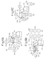
- Fig. 6B shows a second example of combination having such an arrangement.
- the correlation between the plural arrows of the index 20 (or index elements) 20a to 20f and the plural motion command keys 22a to 22f is represented by solid line segments L1, L2, L3. Also, + and - signs indicating the directions of the respective coordinate axes are incorporated into the index 20 to be shown as a drawing and further clarify the correlation between the axes and to the motion command keys 22a to 22f.
- Respective functions of the index 20 and the motion command section 22 are the same as in the first example. For example, the input operation of a "-" key 22b on the right-hand of a character "X" in the motion command section 22 causes the robot mechanical section 12 (Fig. 4) to operate in a jog-feed motion in a -X axis direction in the manual-mode effective coordinate system as presently set.
- a third example as shown in Fig. 6C is configured such that a manual-mode operation is performed by designating a control axis in the robot mechanical section 12 (Fig. 4).
- the index 20 is comprised of a drawing illustrating the directions of motions in a plurality of control axes J1, J2, J3 provided for the robot mechanical section 12. More specifically, the index 20 is composed of six arrows (i.e., index elements) 20g, 20h, 20i, 20j, 20k, 20l respectively representing, near the J1 axis, J2 axis, J3 axis in the robot diagram 18, normal and reverse directions of rotation in the respective control axes.
- the motion command section 22 includes a plurality of motion command keys 22g, 22h, 22i, 22j, 22k, 22l provided adjacent to and individually corresponding to the arrows 20g to 20l.
- the motion command keys 22g to 22l have command input functions for causing the robot mechanical section 12 to perform a motion (a rotational motion, in the illustrated example) in the directions of the corresponding arrows along the three control axes J1, J2, J3 illustrated by the drawing of the index 20.
- the input operation of the motion command key 22g causes the robot mechanical section 12 to operate in a rotational jog-feed motion about the J1 axis in a normal (+) direction
- the input operation of the motion command key 22j causes the robot mechanical section 12 to operate in a rotational jog-feed motion about the J2 axis in a reverse (-) direction.
- two robot diagrams 18 may be provided on the housing 16, and the indexes 20 and the motion command sections 22, having the configurations of the first and third examples as described above, may be provided respectively for the diagrams.
- the robot mechanical section 12 Fig.
- the index 20 and the motion command section 22 may be provided for the remaining control axes (J4 axis to J6 axis), so as to permit the manual operating unit to operate the normal and reverse rotations about the J1 axis to the J6-axis. Further, if an index representing normal and reverse rotational motions about each of the X axis, Y axis and Z axis of the manual-mode effective coordinate system, as well as a corresponding motion command section are provided, it is possible for the manual operating unit to operate the normal and reverse rotational motions about each of X, Y, Z axes.
- the present invention is capable of solving the problems associated with the prior art, in the manual operating unit for a robot, by providing the robot diagram on the housing, incorporating the index including the index elements such as arrows representing the actual direction of motion into the robot diagram, and providing the motion command section including the motion command keys assigned correspondingly to the respective index elements. Therefore, according to the present invention, it is possible, even for an operator who is not skilled in the manual operation of a robot and who cannot properly image a desired coordinate system in the robot system, to readily recognize the direction of the actual motion of the robot mechanical section, and thus to operate the robot mechanical section with no operating error. Further, a touch panel is not used in an input section, so that it is possible to provide the manual operating unit that is excellent in terms of reliability, durability and economy.
Landscapes
- Engineering & Computer Science (AREA)
- Human Computer Interaction (AREA)
- Manufacturing & Machinery (AREA)
- Physics & Mathematics (AREA)
- General Physics & Mathematics (AREA)
- Automation & Control Theory (AREA)
- Robotics (AREA)
- Mechanical Engineering (AREA)
- Manipulator (AREA)
- Numerical Control (AREA)
Abstract
Description
Claims (5)
- A manual operating unit (10) for a robot, comprising:a housing (16);a robot diagram (18) provided on said housing, said robot diagram schematically showing an external appearance of a robot mechanical section (12);an index (20) provided on said housing in association with said robot diagram, said index representing a plurality of directions of motions to be performed by the robot mechanical section under control; anda motion command section (22) provided on said housing in association with said index, said motion command section causing the robot mechanical section to perform said motions in said directions represented by said index.
- A manual operating unit as set forth in claim 1, wherein said index comprises a drawing (20a - 20f) illustrating three coordinate axes (X, Y, Z) of a three-axis rectangular coordinate system provided for the robot mechanical section; and wherein said motion command section comprises a plurality of motion command keys (22a - 22f) for causing the robot mechanical section to perform said motions along said three coordinate axes illustrated by said drawing.
- A manual operating unit as set forth in claim 1, wherein said index comprises a drawing (20g - 20l) illustrating directions of motions in a plurality of control axes (J1, J2, J3) provided for the robot mechanical section; and wherein said motion command section comprises a plurality of motion command keys (22g - 22l) for causing the robot mechanical section to perform said motions along said plurality of control axes illustrated by said drawing.
- A manual operating unit as set forth in claim 1, further comprising a display section (24) provided on said housing independently of said motion command section and an operation key (26) provided on said housing independently of said motion command section and said display section.
- A manual operating unit as set forth in claim 1, further comprising at least one of an enable switch (28), an emergency shutdown switch (30) and a dead man's switch (32), which are provided on said housing independently of said motion command section.
Applications Claiming Priority (2)
| Application Number | Priority Date | Filing Date | Title |
|---|---|---|---|
| JP2004104537A JP2005288581A (en) | 2004-03-31 | 2004-03-31 | Portable teaching operation panel |
| JP2004104537 | 2004-03-31 |
Publications (3)
| Publication Number | Publication Date |
|---|---|
| EP1582956A2 true EP1582956A2 (en) | 2005-10-05 |
| EP1582956A8 EP1582956A8 (en) | 2006-01-11 |
| EP1582956A3 EP1582956A3 (en) | 2007-11-21 |
Family
ID=34880052
Family Applications (1)
| Application Number | Title | Priority Date | Filing Date |
|---|---|---|---|
| EP05006908A Withdrawn EP1582956A3 (en) | 2004-03-31 | 2005-03-30 | Manual operating unit for robot |
Country Status (4)
| Country | Link |
|---|---|
| US (1) | US20050231332A1 (en) |
| EP (1) | EP1582956A3 (en) |
| JP (1) | JP2005288581A (en) |
| CN (1) | CN1677301A (en) |
Cited By (3)
| Publication number | Priority date | Publication date | Assignee | Title |
|---|---|---|---|---|
| ITTV20120138A1 (en) * | 2012-07-25 | 2014-01-26 | Isis S R L | METHOD FOR THE CONTROL AND ACTIVATION OF A USER INTERFACE AND DEVICE AND PLANT WITH THIS METHOD AND INTERFACE |
| EP2957398A4 (en) * | 2013-02-15 | 2017-07-12 | Kabushiki Kaisha Kobe Seiko Sho (Kobe Steel, Ltd.) | Robot pendant |
| US10513039B2 (en) | 2016-12-16 | 2019-12-24 | Fanuc Corporation | Teach pendant and robot system provided with the same |
Families Citing this family (12)
| Publication number | Priority date | Publication date | Assignee | Title |
|---|---|---|---|---|
| FR2879803B1 (en) * | 2004-12-20 | 2007-01-19 | Dav Sa | TOUCH SURFACE ACTIVATION DEVICE, IN PARTICULAR FOR CONTROLS OF A VEHICLE |
| JP4584877B2 (en) * | 2006-07-14 | 2010-11-24 | 日本電産サンキョー株式会社 | Robot teaching system and robot teaching method |
| JP5467508B2 (en) * | 2009-10-30 | 2014-04-09 | 株式会社Ihi | Hand guide device and control method thereof |
| JP5467509B2 (en) * | 2009-10-30 | 2014-04-09 | 株式会社Ihi | Hand guide device and control method thereof |
| JP5467510B2 (en) * | 2009-10-30 | 2014-04-09 | 株式会社Ihi | External operation hand guide device and control method thereof |
| JP5383468B2 (en) * | 2009-12-21 | 2014-01-08 | 三菱電機株式会社 | Robot teaching device |
| CN103197783A (en) * | 2012-01-09 | 2013-07-10 | 豪力辉工业股份有限公司 | Digital teach pendant |
| CA163908S (en) * | 2015-06-12 | 2016-05-26 | Comau Spa | Portable control terminal for industrial machines |
| EP3308229B1 (en) | 2015-06-15 | 2021-09-08 | Comau S.p.A. | Portable safety control device for industrial machines, in particular robots |
| JP6915288B2 (en) * | 2017-02-08 | 2021-08-04 | オムロン株式会社 | Image processing system, image processing device, circuit reconstruction method in FPGA (Field Programmable Gate Array), and circuit reconstruction program in FPGA |
| JP1606242S (en) * | 2017-11-22 | 2018-06-11 | ||
| JP7619070B2 (en) * | 2021-02-10 | 2025-01-22 | セイコーエプソン株式会社 | Teaching device, teaching method, and teaching program |
Family Cites Families (9)
| Publication number | Priority date | Publication date | Assignee | Title |
|---|---|---|---|---|
| CH300264A (en) * | 1947-04-11 | 1954-07-15 | Berthiez Charles William | Selection station for controlling parts of a machine. |
| US5511147A (en) * | 1994-01-12 | 1996-04-23 | Uti Corporation | Graphical interface for robot |
| JPH07295625A (en) * | 1994-04-28 | 1995-11-10 | Fanuc Ltd | Jog feed information display device for robot |
| JP4014662B2 (en) * | 1995-09-18 | 2007-11-28 | ファナック株式会社 | Robot teaching operation panel |
| WO1998003314A1 (en) * | 1996-07-24 | 1998-01-29 | Fanuc Ltd | Jog feeding method for robots |
| JP3901772B2 (en) * | 1996-11-13 | 2007-04-04 | 三菱重工業株式会社 | Robot teaching operation method |
| US6040839A (en) * | 1997-01-31 | 2000-03-21 | Van Eldik; Benjamin J. | Referencing system and method for three-dimensional objects displayed on a computer generated display |
| US6351678B1 (en) * | 1997-11-07 | 2002-02-26 | Hill-Rom Services, Inc. | Medical equipment controller |
| US6366293B1 (en) * | 1998-09-29 | 2002-04-02 | Rockwell Software Inc. | Method and apparatus for manipulating and displaying graphical objects in a computer display device |
-
2004
- 2004-03-31 JP JP2004104537A patent/JP2005288581A/en active Pending
-
2005
- 2005-03-28 US US11/090,235 patent/US20050231332A1/en not_active Abandoned
- 2005-03-30 CN CN200510058887.0A patent/CN1677301A/en active Pending
- 2005-03-30 EP EP05006908A patent/EP1582956A3/en not_active Withdrawn
Cited By (5)
| Publication number | Priority date | Publication date | Assignee | Title |
|---|---|---|---|---|
| ITTV20120138A1 (en) * | 2012-07-25 | 2014-01-26 | Isis S R L | METHOD FOR THE CONTROL AND ACTIVATION OF A USER INTERFACE AND DEVICE AND PLANT WITH THIS METHOD AND INTERFACE |
| EP2690514A2 (en) | 2012-07-25 | 2014-01-29 | ISIS Srl | User interface with integrated dead man switch |
| EP2690514A3 (en) * | 2012-07-25 | 2016-04-13 | ISIS Srl | User interface with integrated dead man switch |
| EP2957398A4 (en) * | 2013-02-15 | 2017-07-12 | Kabushiki Kaisha Kobe Seiko Sho (Kobe Steel, Ltd.) | Robot pendant |
| US10513039B2 (en) | 2016-12-16 | 2019-12-24 | Fanuc Corporation | Teach pendant and robot system provided with the same |
Also Published As
| Publication number | Publication date |
|---|---|
| EP1582956A3 (en) | 2007-11-21 |
| EP1582956A8 (en) | 2006-01-11 |
| CN1677301A (en) | 2005-10-05 |
| JP2005288581A (en) | 2005-10-20 |
| US20050231332A1 (en) | 2005-10-20 |
Similar Documents
| Publication | Publication Date | Title |
|---|---|---|
| US20050231332A1 (en) | Manual operating unit for robot | |
| US6218802B1 (en) | Robot control unit | |
| EP2617530B1 (en) | Master operation input device and master-slave manipulator | |
| JP4014662B2 (en) | Robot teaching operation panel | |
| JP2000079587A (en) | Robot remote control method and system | |
| EP2923806A1 (en) | Robot control device, robot, robotic system, teaching method, and program | |
| KR101010761B1 (en) | Robot control device with robot body and additional mechanism with additional axis of motion | |
| JP2005533326A (en) | Parallel haptic joystick system | |
| JP4347313B2 (en) | Robot teaching operation panel | |
| WO2012062374A1 (en) | A control system and an operating device for controlling an industrial robot comprising a touch -screen | |
| JP2010182235A (en) | Touch panel input device and display control method of the same | |
| CN100537155C (en) | Origin adjustment method for industrial robot | |
| US20240123607A1 (en) | Robot system comprising robot equipped with display unit | |
| JPH11262884A (en) | Robot manual operation device | |
| JP2005339306A (en) | Data input device | |
| JP2003091353A (en) | Input device for HMD | |
| JP2013058219A (en) | Touch panel type input device and screen display method for touch panel type input device | |
| US10932389B2 (en) | Frame member attached to mobile terminal, operation device for machine including frame member, and computer program for mobile terminal | |
| JPH0985660A (en) | Robot teaching device | |
| JPH06328380A (en) | Robot teaching device, industrial robot, and operating device | |
| JP5464252B2 (en) | Touch panel type input device and screen display method of touch panel type input device | |
| CN117331338B (en) | A remote control controller for a mobile robot arm | |
| JPS6171984A (en) | General-purpose master operating section for steering type manipulator | |
| JP2025174046A (en) | Control device for multi-degree-of-freedom input device | |
| JP3196972B2 (en) | Robot direct teaching device |
Legal Events
| Date | Code | Title | Description |
|---|---|---|---|
| PUAI | Public reference made under article 153(3) epc to a published international application that has entered the european phase |
Free format text: ORIGINAL CODE: 0009012 |
|
| AK | Designated contracting states |
Kind code of ref document: A2 Designated state(s): AT BE BG CH CY CZ DE DK EE ES FI FR GB GR HU IE IS IT LI LT LU MC NL PL PT RO SE SI SK TR |
|
| AX | Request for extension of the european patent |
Extension state: AL BA HR LV MK YU |
|
| RIN1 | Information on inventor provided before grant (corrected) |
Inventor name: YAMASHIRO, HIKARU Inventor name: YASUMURA, MITSUHIRO Inventor name: KINOSHITA, SATOSHI Inventor name: NIHEI, RYO |
|
| PUAL | Search report despatched |
Free format text: ORIGINAL CODE: 0009013 |
|
| AK | Designated contracting states |
Kind code of ref document: A3 Designated state(s): AT BE BG CH CY CZ DE DK EE ES FI FR GB GR HU IE IS IT LI LT LU MC NL PL PT RO SE SI SK TR |
|
| AX | Request for extension of the european patent |
Extension state: AL BA HR LV MK YU |
|
| RIC1 | Information provided on ipc code assigned before grant |
Ipc: B25J 13/02 20060101ALI20071016BHEP Ipc: G05B 19/409 20060101AFI20071016BHEP |
|
| 17P | Request for examination filed |
Effective date: 20071212 |
|
| AKX | Designation fees paid |
Designated state(s): DE |
|
| STAA | Information on the status of an ep patent application or granted ep patent |
Free format text: STATUS: THE APPLICATION HAS BEEN WITHDRAWN |
|
| 18W | Application withdrawn |
Effective date: 20080820 |