EP1582861A2 - Photography control apparatus and program - Google Patents
Photography control apparatus and program Download PDFInfo
- Publication number
- EP1582861A2 EP1582861A2 EP05006931A EP05006931A EP1582861A2 EP 1582861 A2 EP1582861 A2 EP 1582861A2 EP 05006931 A EP05006931 A EP 05006931A EP 05006931 A EP05006931 A EP 05006931A EP 1582861 A2 EP1582861 A2 EP 1582861A2
- Authority
- EP
- European Patent Office
- Prior art keywords
- photography
- intervals
- data sets
- unit
- control apparatus
- Prior art date
- Legal status (The legal status is an assumption and is not a legal conclusion. Google has not performed a legal analysis and makes no representation as to the accuracy of the status listed.)
- Granted
Links
Images



Classifications
-
- G—PHYSICS
- G03—PHOTOGRAPHY; CINEMATOGRAPHY; ANALOGOUS TECHNIQUES USING WAVES OTHER THAN OPTICAL WAVES; ELECTROGRAPHY; HOLOGRAPHY
- G03B—APPARATUS OR ARRANGEMENTS FOR TAKING PHOTOGRAPHS OR FOR PROJECTING OR VIEWING THEM; APPARATUS OR ARRANGEMENTS EMPLOYING ANALOGOUS TECHNIQUES USING WAVES OTHER THAN OPTICAL WAVES; ACCESSORIES THEREFOR
- G03B15/00—Special procedures for taking photographs; Apparatus therefor
-
- G—PHYSICS
- G01—MEASURING; TESTING
- G01N—INVESTIGATING OR ANALYSING MATERIALS BY DETERMINING THEIR CHEMICAL OR PHYSICAL PROPERTIES
- G01N21/00—Investigating or analysing materials by the use of optical means, i.e. using sub-millimetre waves, infrared, visible or ultraviolet light
- G01N21/62—Systems in which the material investigated is excited whereby it emits light or causes a change in wavelength of the incident light
- G01N21/63—Systems in which the material investigated is excited whereby it emits light or causes a change in wavelength of the incident light optically excited
- G01N21/64—Fluorescence; Phosphorescence
- G01N21/6428—Measuring fluorescence of fluorescent products of reactions or of fluorochrome labelled reactive substances, e.g. measuring quenching effects, using measuring "optrodes"
-
- G—PHYSICS
- G01—MEASURING; TESTING
- G01N—INVESTIGATING OR ANALYSING MATERIALS BY DETERMINING THEIR CHEMICAL OR PHYSICAL PROPERTIES
- G01N21/00—Investigating or analysing materials by the use of optical means, i.e. using sub-millimetre waves, infrared, visible or ultraviolet light
- G01N21/62—Systems in which the material investigated is excited whereby it emits light or causes a change in wavelength of the incident light
- G01N21/63—Systems in which the material investigated is excited whereby it emits light or causes a change in wavelength of the incident light optically excited
- G01N21/64—Fluorescence; Phosphorescence
- G01N21/645—Specially adapted constructive features of fluorimeters
- G01N21/6456—Spatial resolved fluorescence measurements; Imaging
Definitions
- the present invention relates to a photography system that images a subject, which is provided within a frame.
- Apparatuses that place subjects within frames, and image the subjects by irradiating the subjects with a light source provided within the frame, are utilized in various fields.
- a fluorescence detecting system that utilizes fluorescent materials as marker substances is known in the field of biochemistry.
- the fluorescence detecting system is capable of evaluating gene sequences, levels of gene expression, separation, fixation, molecular weights and characteristics of proteins, and the like, by reading out fluorescence images.
- fluorescent dyes are added to a solution that includes a plurality of DNA fragments which are to be subjected to electrophoresis. Then, the plurality of DNA fragments are caused to undergo electrophoresis on a gel substrate. Alternatively, a plurality of DNA fragments may be caused to undergo electrophoresis on a gel substrate that contains fluorescent dyes. After the plurality of DNA fragments undergo electrophoresis on the gel substrate, the DNA fragments are marked by soaking the gel substrate in a solution that contains fluorescent dyes or the like. Then, the fluorescent dyes are excited by excitation light, and fluorescence generated by the excitation is detected to form an image. Thereby, the DNA distribution on the gel substrate can be detected.
- a plurality of DNA fragments may be caused to undergo electrophoresis on a gel substrate, then denatured. Next, at least a portion of the denatured DNA fragments are transferred onto a transfer substrate such as cellulose nitrate by the Southern Blotting method.
- a probe which is prepared by marking a DNA which is complementary to a target DNA with fluorescent dye or by marking RNA with fluorescent dye, is hybridized with the denatured DNA fragments. The DNA fragments, which are complementary to the probe DNA or the probe RNA, are selectively marked. Then, the fluorescent dyes are excited by excitation light, and fluorescence generated by the excitation is detected to form an image. Thereby, the distribution of target DNA on the transfer substrate can be detected.
- micro array analysis systems are gathering attention as a biochemical analytic system.
- micro array analysis systems that utilize fluorescent materials as marker substances.
- specific bonding materials which specifically bind with tissue derived substances and of which base sequences and base lengths are known, are spotted on different positions of a carrier such as a glass slide or a membrane filter by a spotter apparatus, thereby forming a plurality of independent spots.
- the specific bonding materials include: hormones, tumor markers, enzymes, antibodies, antigens, abzymes, other proteins, nucleic acids, cDNA, DNA, and RNA.
- tissue derived substances which are collected from tissue by extraction, isolation or the like, or tissue derived substances, which have been chemically processed or chemically modified and marked with a fluorescent marker substance such as fluorescent dyes, are specifically bonded with the specific bonding materials by hybridization or the like.
- the tissue derived substances include: hormones, tumor markers, enzymes, antibodies, antigens, abzymes, other proteins, nucleic acids, cDNA, DNA, and mRNA.
- the micro array, on which the specifically bound materials are arranged is excited by excitation light, and fluorescence generated by the excitation of fluorescent materials and marker substances is photoelectrically detected. Thereby, the tissue derived materials are analyzed.
- chemiluminescence methods that utilize chemiluminescence reactions, in which substances emit light during chemical reactions, have also been proposed.
- the chemiluminescence methods may be employed to inspect and research (genetic analysis, diagnosis, aging) living tissue, or to evaluate deterioration of organic compounds and polymeric compounds.
- tissue derived substances are marked with antigens.
- Antibodies are marked with marker substances that generate chemical luminescence when they come into contact with chemically luminescent ground substances.
- the tissue derived substances are brought into contact with the antibodies, then brought into contact with the chemically luminescent ground substances, to generate chemiluminescence.
- the fluorescence and the chemiluminescence which are to be detected in the aforementioned fluorescence methods and the chemiluminescence methods, are extremely faint. Therefore, subjects are hosed within a light shielding frame, and the fluorescence or the chemiluminescence emitted by the subject is detected by a cooled CCD (photography unit), as disclosed in U.S. Patent Application Publication No. 20030214581.
- a cooled CCD photography unit
- an excitation light source provided within the frame irradiates excitation light onto the subject.
- the fluorescence emitted by the subject due to the excitation is focused as a visible image on the cooled CCD via a high sensitivity lens.
- the excitation light source is not activated, and the luminescence emitted by the subject is focused as a visible image on the cooled CCD via the high sensitivity lens.
- the present invention has been developed in view of the above circumstances. It is an object of the present invention to provide a photography control apparatus and a photography control program, which are capable of efficiently and automatically photographing a subject a plurality of times.
- the photography control apparatus of the present invention is an apparatus for controlling a photography apparatus, comprising:
- the photography control program of the present invention is a program for realizing functions that control a photography apparatus, comprising:
- the input receiving means receives input of photography intervals, that is, the interval between completion of a previous photography operation and initiation of a next photography operation, for the second and later photography operations.
- the input receiving means may either receive or not receive input of a photography interval for the first photography operation.
- a photography interval for the first photography operation is set, a time interval between issuance of a photography command and the initiation of the first photography operation is set.
- the "interval between completion of a previous photography operation and initiation of a next photography operation” may be a time interval between a time that the photography unit completes a photography operation and a time that the photography unit initiates a next photography operation.
- the “interval” may be a time interval between a time that image processes are completed on an image data set obtained by the photography unit and a time that the photography unit initiates a next photography operation.
- the photography control apparatus may further comprise storage means for storing a plurality of template data sets, in which photography intervals are set in advance.
- the input receiving means reads out one of the template data sets from the storage means and receives input of the photography intervals, which is set in the template data set.
- the input receiving means may have a function of correcting the photography intervals, which are set in the template data sets.
- the photography control means may control the photography unit to perform the plurality of photography operations, based on the corrected photography intervals which are set in the corrected template data sets. Note that the correction of the photography intervals may be administered on a portion or on all of the photography intervals which are set in the template data sets.
- the photography control apparatus may further comprise a display unit and display control means for displaying the photography intervals, which are received by the input receiving means, on the display unit.
- the display control means may have a function of displaying that the template data set has been corrected, in the case that the input receiving means corrects the template data set.
- the display control means may have a function of displaying the image data sets, which have been obtained by the photography unit.
- the display control means may display the image data sets on the display unit, correlated with the photography intervals at which the image data sets were obtained.
- the photography control apparatus and the photography control program of the present invention perform the functions of receiving input of photography intervals between completion of a previous photography operation and initiation of a next photography operation; and controlling the photography unit to perform a plurality of photography operations, based on the photography intervals received by the input receiving means. Therefore, users are enabled to set desired photography timings for each photography operation during repeated photography of a subject. Accordingly, problems such as obtainment of unnecessary image data sets and an inability to obtain desired image data sets are prevented, and efficient and automatic photography of a subject a plurality of times becomes possible.
- the photography control apparatus may further comprise: storage means for storing a plurality of template data sets, in which photography intervals are set in advance; wherein:
- the input receiving means may have a function of correcting the photography intervals, which are set in the template data sets.
- the photography control means may control the photography unit to perform the plurality of photography operations, based on the corrected photography intervals which are set in the corrected template data sets. If this configuration is adopted, setting of the image intervals is facilitated when users desire to correct a portion of the template data sets, because it is not necessary to re-input the photography intervals for each photography operation.
- the photography control apparatus may further comprise: a display unit; and display control means for displaying the photography intervals, which are received by the input receiving means, on the display unit.
- the display control means may have a function of displaying that the template data set has been corrected, in the case that the input receiving means corrects the template data set. If this configuration is adopted, whether the template data set to be utilized for repeated photography has been corrected can be confirmed easily, without referring to each of the plurality of photography intervals set within the template data set. Therefore, the convenience for users is improved.
- the display control means may have a function of displaying the image data sets, which have been obtained by the photography unit.
- the display control means may display the image data sets on the display unit, correlated with the photography intervals at which the image data sets were obtained. If this configuration is adopted, users are enabled to view the image data sets and the photography intervals simultaneously. Therefore, the convenience for users is further improved.
- FIG. 1 is a perspective view of a photography system 1 that utilizes the photography control apparatus of the present invention.
- the photography system 1 is a fluorescence detecting system for displaying fluorescence images by irradiating excitation light onto subjects, which are fluorescent materials.
- the photography system 1 comprises a photography apparatus 10 and a photography control apparatus 100.
- the photography apparatus 10 and the photography control apparatus 100 are to be used on a desktop.
- the photography control apparatus 100 may be a personal computer, for example, which is connected to input means 2, such as a mouse and a keyboard, and a display unit 3, such as a CRT or LCD monitor.
- the photography apparatus 10 photographs a subject PS and transmits image data sets of the subject PS to the photography control apparatus 100.
- the photography control apparatus 100 administers image processes on the image data sets, and displays the image data sets on the display unit 3.
- the subject may be a test substance that emits luminescence when it comes into contact with a chemically luminescent ground substance (chemiluminescence method).
- the subject may be test substance which is marked with fluorescent dye that emits fluorescence when irradiated by excitation light (fluorescence method).
- FIG 2 is a schematic view that illustrates a preferred embodiment of the photography apparatus 10 in the photography system 1 of the present invention.
- the photography apparatus 10 illustrated in Figure 2 comprises: a frame 20; and a photography unit 30.
- the frame 20 houses subjects therein.
- the photography unit 30 photographs subjects which are housed within the frame 20, and outputs image data sets.
- the frame 20 is formed substantially as a parallelepiped having a hollow portion 21.
- a subject placement unit 40 on which subjects PS are placed, is provided in the interior of the frame 20.
- a lid 22 is removably attached to the frame 20, to enable users to open the lid 22 and place subjects inside the frame 20.
- the frame 20 is constituted to be a darkroom, having the hollow portion 21 into which external light does not enter. Therefore, photography is enabled even if the light emitted from the subject is faint.
- the photography unit 30 is fixed on the upper surface 20a of the frame 20.
- the photography unit 30 is configured to photograph the subject PS, which is placed within the frame 20, and to output image data sets.
- a cooling unit (not shown) is mounted on the photography unit 30.
- the cooling unit is provided to cool the photography unit 30, to prevent noise components due to dark current from being included in image data sets obtained thereby.
- a lens unit 31, which is to be focused on the subject PS, is mounted on the photography unit 30.
- Incident light sources 50 and a bottom light source 60 are provided within the frame 20.
- the incident light sources 50 irradiate excitation light onto the subject PS, which is a luminescent material, to cause the subject PS to emit light.
- the incident light sources 50 are provided above the subject placement unit 40.
- the bottom light source 60 irradiates excitation light onto the subject from below.
- FIG 3 is a schematic view that illustrates a preferred embodiment of the photography control apparatus 100 according to the present invention.
- the photography control apparatus 100 will be described with reference to Figure 1 and Figure 3.
- the structures of the photography control apparatus 100 illustrated in Figure 3 are realized by executing a photography control program, which is written into an auxiliary memory apparatus, on a computer (for example, a personal computer).
- the photography control program may be recorded in data recording media such as CD-ROM's and distributed, or distributed via networks such as the Internet, and installed on computers.
- the photography control apparatus 100 controls the photography apparatus 10 to perform a plurality of photography operations to image the subject PS.
- the photography control apparatus 100 comprises: input receiving means 110; photography control means 120, display control means 140; and image obtaining means 130.
- the input receiving means 110 receives input of photography intervals, that is, time intervals between completion of a previous photography operation and initiation of a next photography operation, for each photography operation.
- the photography control means 120 controls the photography unit 30 to perform a plurality of photography operations at the photography intervals received by the input receiving means 110.
- the display control means 140 displays the photography intervals received by the input receiving means 110 on the display unit 3.
- the image obtaining means 130 obtains image data sets, which have been imaged by the photography apparatus 10.
- the display control means 140 is configured to display a photography condition setting window TW, as illustrated in Figure 4, during reception of the time intervals by the input receiving means 110. Input is received from the input means 2.
- the photography condition setting window TW comprises a plurality of condition setting frames 210. Each of the condition setting frames enables setting of a photography interval PI and an exposure time. When an exposure count (number of times photography is to be performed) is specified, the same number of frames 210 are activated.
- the input receiving means 110 receives input of the photography intervals PI and the exposure times within the frames 210 from the input means 2.
- the photography control apparatus 100 illustrated in Figure 3 further comprises storage means TP, in which a plurality of template data sets are stored.
- the template data sets have photography intervals for each photography operation set therein in advance.
- the input receiving means 110 is configured to read out a template data set from within the storage means TP, and to receive input of each of the photography intervals which are set in the template data set.
- the photography condition setting window TW comprises a template combination box 220, which is used to select a template data set to be utilized.
- the template combination box 220 is configured to display the names of the plurality of template data sets so that they are selectable.
- the photography sensitivity, the number of photography operations, the photography intervals PI and the exposure times, which are preset in the template data set are automatically input into the condition setting frames 210.
- the input receiving means 110 is configured to receive input of the photography intervals PI, which are preset in the template data set.
- additional information such as comments regarding subjects on which a template data set is used, and characteristics of the template data set, are included in the template data sets, along with the photography sensitivity, the number of photography operations, the photography intervals, and exposure times.
- the additional information is displayed in a template comment box 240.
- the input receiving means 110 has a function of receiving corrections to the photography intervals which are set in the template data sets.
- the photography control means 120 is configured to control the photography unit to photograph the subject PS at the photography intervals which are set in the corrected template data sets. Specifically, when a template data set is selected as described above, the photography sensitivity, the number of photography operations, the photography intervals PI, and the exposure times, which are set in the template data set, are automatically input to the frames 210. At this time, the photography sensitivity, the number of photography operations, and the photography intervals PI and the exposure times within each condition setting frame 210 are correctable.
- the input receiving means 110 is configured to receive settings of a corrected template data set, if users use the input means 2 to correct a portion or the entirety of the photography sensitivity, the number of photography operations, the photography intervals and the exposure times. Therefore, in cases that a portion of the template data set is desired to be corrected, it is not necessary to re-input values for each photography operation. Accordingly, the setting of photography conditions is facilitated.
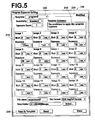
- the display control means 140 has a function of displaying that template data sets have been corrected on the display unit 3, in the case that the input receiving means 110 receives corrections to the template data sets, as illustrated in the upper right corner of Figure 5, for example. Thereby, whether a template data set to be utilized for repeated photography has been corrected can be confirmed easily, without referring to each of the plurality of photography intervals set within the template data set. Therefore, the convenience for users is improved.
- the display control means 140 also has a function of displaying image data sets, which have been obtained by the photography unit 30, on the display unit 3.
- the display control means 140 is configured to display a plurality of image data sets, correlated with the photography intervals and the exposure times during obtainment thereof.
- the display control means 140 has a function of displaying a preview window PW, in which a plurality of image data sets are arranged, on the display unit 3, as illustrated in Figure 6.
- the display control means 140 is configured to display an image data set PD within a picture box PB of the preview window PW, every time that the image obtaining means 130 obtains an image data set from the photography apparatus 10.
- the display control means 140 is configured to display the photography interval PI and the exposure time which were employed during photography of the image data set in the picture box PB. Thereby, users are enabled to confirm both the image data set and the photography interval simultaneously. Accordingly, the convenience for users is improved. Note that if users select a picture box PB within the preview window, the image data set within the picture box PB is enlarged and displayed.
- the display control means 140 first displays the same number of picture boxes PB as the number of photography operations, which is set in the condition setting window TW, in the preview window PW. Then, as the image obtaining means 110 obtains image data sets PD, the image data sets PD are displayed within the picture boxes PB. This configuration enables users to recognize how many photography operations remain, during repeated photography.
- FIG 7 is a flow chart that illustrates an example of the processes performed by the photography control apparatus 100.
- the processes performed by the photography control apparatus 100 will be described with reference to Figures 1 through 7.
- the display control means 140 displays the condition setting window TW on the display unit 3, as illustrated in Figure 4 (step ST1) .
- a user inputs photography intervals PI and exposure times in each condition setting frame 210, or selects a template data set from the template combination box 220 (step ST2) .
- the input receiving means 110 receives the photography sensitivity, the number of photography operations, the photography intervals PI and the exposure times, and the photography control means 120 causes the photography apparatus 10 to perform photography of the subject PS according to the input settings (step ST3).
- photography is performed with the exposure time set within the condition setting frame 210 for Image 1, after the photography interval PI for Image 1 has passed, as illustrated in Figure 4. Thereafter, readout of image data sets from the photography unit 30 and data processes, such as image processes, are performed.
- the photography intervals PI are time intervals that begin after readout of data from the photography unit 30 and data processes, such as image processes, are completed.
- the photography intervals PI may be time intervals that begin immediately following completion of photography by the photography unit 30.
- the display control means 140 causes image data sets to be displayed within the picture boxes PB of the preview window PW illustrated in Figure 6, along with the photography intervals PI and the exposure times, every time that the image obtaining means 130 obtains an image data set from the photography apparatus 10.
- the photography control apparatus comprises: the input receiving means 110, for receiving input of photography intervals between completion of a previous photography operation to initiation of a next photography operation; and the photography control means 120, for controlling the photography unit 30 to perform a plurality of photography operations according to the photography intervals which have been received by the input receiving means 110. Therefore, users are enabled to set desired photography timings for each photography operation during repeated photography of a subject. Accordingly, problems such as obtainment of unnecessary image data sets and an inability to obtain desired image data sets are prevented, and efficient and automatic photography of a subj ect a plurality of times becomes possible.
- the photography control apparatus may further comprise: the storage means TP for storing a plurality of template data sets, in which photography intervals are set in advance, as illustrated in Figure 3.
- the input receiving means 110 reads out one of the template data sets from the storage means TP and receives input of the photography intervals, which is set in the template data set. If this configuration is adopted, users are not required to set the photography intervals every time that repeated photography is to be performed. Accordingly, the photography intervals are enabled to be set efficiently.
- the input receiving means 110 may have a function of correcting the photography intervals, which are set in the template data sets.
- the photography control means 120 may control the photography unit to perform the plurality of photography operations, based on the corrected photography intervals which are set in the corrected template data sets. If this configuration is adopted, setting of the image intervals is facilitated when users desire to correct a portion of the template data sets, because it is not necessary to re-input the photography intervals for each photography operation.
- the photography control apparatus may further comprise: the display unit 3; and the display control means 140 for displaying the photography intervals, which are received by the input receiving means 110, on the display unit 3.
- the display control means 140 may have a function of displaying that the template data set has been corrected, in the case that the input receiving means corrects the template data set, as illustrated in Figure 5. If this configuration is adopted, whether the template data set to be utilized for repeated photography has been corrected can be confirmed easily, without referring to each of the plurality of photography intervals set within the template data set. Therefore, the convenience for users is improved.
- the display control means 140 may have a function of displaying the image data sets, which have been obtained by the photography unit.
- the display control means may display the image data sets on the display unit, correlated with the photography intervals at which the image data sets were obtained. If this configuration is adopted, users are enabled to view the image data sets and the photography intervals simultaneously. Therefore, the convenience for users is further improved.
- a warning indicating that settings are not within allowable ranges may be output from the display control means 140 to the display 3, in the case that an exposure time of 50 hours is set, for example.
- the display control means 140 may display the last image data set obtained, from among a plurality of image data sets, with different gradation in the picture box PB illustrated in Figure 6.
- a "Stop” button for causing photography to be ceased, may be provided in the preview window PW of Figure 6. If users press the "Stop” button, the photography control means 140 causes the photography unit 30 to cease photography operations.
Landscapes
- Health & Medical Sciences (AREA)
- Physics & Mathematics (AREA)
- General Physics & Mathematics (AREA)
- Immunology (AREA)
- Chemical & Material Sciences (AREA)
- Biochemistry (AREA)
- Life Sciences & Earth Sciences (AREA)
- General Health & Medical Sciences (AREA)
- Nuclear Medicine, Radiotherapy & Molecular Imaging (AREA)
- Analytical Chemistry (AREA)
- Pathology (AREA)
- Chemical Kinetics & Catalysis (AREA)
- Optics & Photonics (AREA)
- Studio Devices (AREA)
- Investigating, Analyzing Materials By Fluorescence Or Luminescence (AREA)
- Investigating Or Analysing Materials By The Use Of Chemical Reactions (AREA)
- Details Of Cameras Including Film Mechanisms (AREA)
- Cameras Adapted For Combination With Other Photographic Or Optical Apparatuses (AREA)
Abstract
Description
The photography control apparatus may further comprise storage means for storing a plurality of template data sets, in which photography intervals are set in advance. In this case, the input receiving means reads out one of the template data sets from the storage means and receives input of the photography intervals, which is set in the template data set.
Claims (9)
- A photography control apparatus for controlling a photography apparatus, comprising:a frame for housing a subject within its interior; anda photography unit for photographing the subject within the frame a plurality of times and for outputting image data sets obtained by each photography operation; the photography control apparatus being characterized by comprising:input receiving means for receiving input of photography intervals between completion of a previous photography operation and initiation of a next photography operation; andphotography control means for controlling the photography unit to perform a plurality of photography operations, based on the photography intervals received by the input receiving means.
- A photography control apparatus as defined in Claim 1, further comprising:a display unit; anddisplay control means for displaying the photography intervals, which are received by the input receiving means, on the display unit.
- A photography control apparatus as defined in Claim 2, further comprising:storage means for storing a plurality of template data sets, in which photography intervals are set in advance; wherein:the input receiving means reads out one of the template data sets from the storage means and receives input of the photography intervals, which is set in the template data set.
- A photography control apparatus as defined in Claim 3, wherein:the input receiving means has a function of correcting the photography intervals, which are set in the template data sets; andthe photography control means controls the photography unit to perform the plurality of photography operations, based on the corrected photography intervals which are set in the corrected template data sets.
- A photography control apparatus as defined in Claim 4, wherein:the display control means has a function of displaying that the template data set has been corrected, in the case that the input receiving means corrects the template data set.
- A photography control apparatus as defined in Claim 5, wherein:the display control means has a function of displaying the image data sets, which have been obtained by the photography unit.
- A photography control apparatus as defined in Claim 6, wherein:the display control means displays the image data sets on the display unit, correlated with the photography intervals at which the image data sets were obtained.
- A photography control program for controlling a photography apparatus that comprises: a frame for housing a subject within its interior; and a photography unit for photographing the subject within the frame a plurality of times and for outputting image data sets obtained by each photography operation; the program being characterized by comprising the functions of:receiving input of photography intervals between completion of a previous photography operation and initiation of a next photography operation; andcontrolling the photography unit to perform a plurality of photography operations, based on the photography intervals received by the input receiving means.
- A computer readable medium having the program defined in Claim 8 recorded therein.
Applications Claiming Priority (2)
| Application Number | Priority Date | Filing Date | Title |
|---|---|---|---|
| JP2004105850A JP4034288B2 (en) | 2004-03-31 | 2004-03-31 | Imaging control apparatus and program |
| JP2004105850 | 2004-03-31 |
Publications (3)
| Publication Number | Publication Date |
|---|---|
| EP1582861A2 true EP1582861A2 (en) | 2005-10-05 |
| EP1582861A3 EP1582861A3 (en) | 2006-04-19 |
| EP1582861B1 EP1582861B1 (en) | 2018-07-25 |
Family
ID=34880080
Family Applications (1)
| Application Number | Title | Priority Date | Filing Date |
|---|---|---|---|
| EP05006931.9A Ceased EP1582861B1 (en) | 2004-03-31 | 2005-03-30 | Photography control apparatus and program |
Country Status (3)
| Country | Link |
|---|---|
| US (1) | US7576774B2 (en) |
| EP (1) | EP1582861B1 (en) |
| JP (1) | JP4034288B2 (en) |
Family Cites Families (18)
| Publication number | Priority date | Publication date | Assignee | Title |
|---|---|---|---|---|
| US4466721A (en) * | 1983-03-30 | 1984-08-21 | Gregory Detuzzi | Time lapse programmer |
| US5485200A (en) * | 1990-12-26 | 1996-01-16 | Asahi Kogaku Kogyo Kabushiki Kaisha | Operational information renewing and memorizing apparatus and method for a photographing instrument |
| US6416959B1 (en) * | 1997-02-27 | 2002-07-09 | Kenneth Giuliano | System for cell-based screening |
| JP3861396B2 (en) * | 1997-08-01 | 2006-12-20 | 株式会社ニコン | Microscope image acquisition device |
| US6674485B2 (en) * | 1998-08-31 | 2004-01-06 | Hitachi Software Engineering Co., Ltd. | Apparatus and method for image compositing |
| JP4016505B2 (en) * | 1998-10-07 | 2007-12-05 | アイシン精機株式会社 | Monitoring system for long exposure photography |
| JP3678397B2 (en) * | 1998-12-15 | 2005-08-03 | 富士写真フイルム株式会社 | Shooting system |
| JP3853532B2 (en) * | 1999-02-15 | 2006-12-06 | 富士写真フイルム株式会社 | Photographing method and photographing apparatus |
| CA2392534A1 (en) * | 1999-11-30 | 2001-06-07 | Oncosis | Method and apparatus for selectively targeting specific cells within a cell population |
| US7053933B2 (en) * | 2000-04-04 | 2006-05-30 | Canon Kabushiki Kaisha | Image pickup apparatus having an automatic mode control |
| JP4146991B2 (en) * | 2000-09-18 | 2008-09-10 | キヤノン株式会社 | Electronic camera system, electronic camera, and control method of electronic camera system |
| JP3913972B2 (en) * | 2000-11-20 | 2007-05-09 | 富士フイルム株式会社 | Image data generation method and apparatus |
| JP5015381B2 (en) * | 2001-03-22 | 2012-08-29 | オリンパス株式会社 | Photomicroscope |
| JP2002310894A (en) | 2001-04-11 | 2002-10-23 | Japan Science & Technology Corp | Luminescence observation device, luminous body selection device, and luminous body selection method |
| US7053936B2 (en) * | 2001-04-23 | 2006-05-30 | Nikon Corporation | Electronic camera and photographic information data file management method |
| DE10202050A1 (en) * | 2002-01-18 | 2003-07-31 | Siemens Ag | Imaging of live small animals using luminescence techniques for biological, medical and pharmaceutical research, whereby LEDs are used as a cost effective and low-power light source that provides sufficient excitation light energy |
| JP3723145B2 (en) * | 2002-03-28 | 2005-12-07 | 富士写真フイルム株式会社 | Imaging apparatus, image processing apparatus, and imaging system |
| JP2004233664A (en) * | 2003-01-30 | 2004-08-19 | Olympus Corp | Microscopic image acquisition device and method therefor |
-
2004
- 2004-03-31 JP JP2004105850A patent/JP4034288B2/en not_active Expired - Fee Related
-
2005
- 2005-03-30 EP EP05006931.9A patent/EP1582861B1/en not_active Ceased
- 2005-03-31 US US11/094,361 patent/US7576774B2/en not_active Expired - Fee Related
Also Published As
| Publication number | Publication date |
|---|---|
| JP2005291856A (en) | 2005-10-20 |
| US7576774B2 (en) | 2009-08-18 |
| US20050219369A1 (en) | 2005-10-06 |
| EP1582861B1 (en) | 2018-07-25 |
| EP1582861A3 (en) | 2006-04-19 |
| JP4034288B2 (en) | 2008-01-16 |
Similar Documents
| Publication | Publication Date | Title |
|---|---|---|
| JP6158318B2 (en) | Nucleic acid analyzer and nucleic acid analysis method using the same | |
| JPH1021373A (en) | Picture analyzing device | |
| JP3723145B2 (en) | Imaging apparatus, image processing apparatus, and imaging system | |
| JP2001283190A (en) | Picture processor | |
| JP2007003323A (en) | Photographing system | |
| JP4724126B2 (en) | Biochemical inspection apparatus and biochemical inspection method | |
| EP1582861B1 (en) | Photography control apparatus and program | |
| JP2002181708A (en) | Microarray chip reading method and apparatus therefor | |
| JP3896390B2 (en) | Voltage value setting method for scanner and scanner photomultiplier | |
| US6351286B1 (en) | Image producing apparatus enabling a user to evaluate an intermediate image | |
| US6822242B2 (en) | Image data producing method and apparatus | |
| JP2003298952A (en) | Ccd imaging apparatus | |
| US20050219368A1 (en) | Photography system | |
| JP2017198609A (en) | Image processing method, image processing apparatus, and program | |
| EP2988490B1 (en) | Photographing apparatus and method | |
| JPH10222652A (en) | Image analyzing device | |
| JP2001101424A (en) | Image analyzer | |
| JP4571543B2 (en) | Imaging device | |
| JPH10215395A (en) | Image generator | |
| JPH1051639A (en) | Image processor | |
| JPH10215404A (en) | Image pickup device | |
| JP2003189194A (en) | Cooling ccd camera | |
| JPH0814862A (en) | Image analyzing device | |
| JP2000163591A (en) | Device for analyzing picture | |
| JP2001216497A (en) | Image analyzing device |
Legal Events
| Date | Code | Title | Description |
|---|---|---|---|
| PUAI | Public reference made under article 153(3) epc to a published international application that has entered the european phase |
Free format text: ORIGINAL CODE: 0009012 |
|
| AK | Designated contracting states |
Kind code of ref document: A2 Designated state(s): AT BE BG CH CY CZ DE DK EE ES FI FR GB GR HU IE IS IT LI LT LU MC NL PL PT RO SE SI SK TR |
|
| AX | Request for extension of the european patent |
Extension state: AL BA HR LV MK YU |
|
| PUAL | Search report despatched |
Free format text: ORIGINAL CODE: 0009013 |
|
| AK | Designated contracting states |
Kind code of ref document: A3 Designated state(s): AT BE BG CH CY CZ DE DK EE ES FI FR GB GR HU IE IS IT LI LT LU MC NL PL PT RO SE SI SK TR |
|
| AX | Request for extension of the european patent |
Extension state: AL BA HR LV MK YU |
|
| RIC1 | Information provided on ipc code assigned before grant |
Ipc: G03B 17/40 20060101ALI20060227BHEP Ipc: G01N 21/64 20060101AFI20050712BHEP |
|
| 17P | Request for examination filed |
Effective date: 20061019 |
|
| AKX | Designation fees paid |
Designated state(s): DE FR GB SE |
|
| RAP1 | Party data changed (applicant data changed or rights of an application transferred) |
Owner name: FUJIFILM CORPORATION |
|
| 17Q | First examination report despatched |
Effective date: 20071228 |
|
| STAA | Information on the status of an ep patent application or granted ep patent |
Free format text: STATUS: EXAMINATION IS IN PROGRESS |
|
| GRAP | Despatch of communication of intention to grant a patent |
Free format text: ORIGINAL CODE: EPIDOSNIGR1 |
|
| STAA | Information on the status of an ep patent application or granted ep patent |
Free format text: STATUS: GRANT OF PATENT IS INTENDED |
|
| INTG | Intention to grant announced |
Effective date: 20180208 |
|
| GRAS | Grant fee paid |
Free format text: ORIGINAL CODE: EPIDOSNIGR3 |
|
| GRAA | (expected) grant |
Free format text: ORIGINAL CODE: 0009210 |
|
| STAA | Information on the status of an ep patent application or granted ep patent |
Free format text: STATUS: THE PATENT HAS BEEN GRANTED |
|
| AK | Designated contracting states |
Kind code of ref document: B1 Designated state(s): DE FR GB SE |
|
| REG | Reference to a national code |
Ref country code: GB Ref legal event code: FG4D |
|
| REG | Reference to a national code |
Ref country code: DE Ref legal event code: R096 Ref document number: 602005054303 Country of ref document: DE |
|
| PG25 | Lapsed in a contracting state [announced via postgrant information from national office to epo] |
Ref country code: SE Free format text: LAPSE BECAUSE OF FAILURE TO SUBMIT A TRANSLATION OF THE DESCRIPTION OR TO PAY THE FEE WITHIN THE PRESCRIBED TIME-LIMIT Effective date: 20180725 |
|
| RIC2 | Information provided on ipc code assigned after grant |
Ipc: G03B 17/40 20060101ALI20060227BHEP Ipc: G01N 21/64 20060101AFI20050712BHEP |
|
| REG | Reference to a national code |
Ref country code: DE Ref legal event code: R097 Ref document number: 602005054303 Country of ref document: DE |
|
| PGFP | Annual fee paid to national office [announced via postgrant information from national office to epo] |
Ref country code: DE Payment date: 20190319 Year of fee payment: 15 |
|
| PLBE | No opposition filed within time limit |
Free format text: ORIGINAL CODE: 0009261 |
|
| STAA | Information on the status of an ep patent application or granted ep patent |
Free format text: STATUS: NO OPPOSITION FILED WITHIN TIME LIMIT |
|
| 26N | No opposition filed |
Effective date: 20190426 |
|
| GBPC | Gb: european patent ceased through non-payment of renewal fee |
Effective date: 20190330 |
|
| PG25 | Lapsed in a contracting state [announced via postgrant information from national office to epo] |
Ref country code: GB Free format text: LAPSE BECAUSE OF NON-PAYMENT OF DUE FEES Effective date: 20190330 |
|
| PG25 | Lapsed in a contracting state [announced via postgrant information from national office to epo] |
Ref country code: FR Free format text: LAPSE BECAUSE OF NON-PAYMENT OF DUE FEES Effective date: 20190331 |
|
| REG | Reference to a national code |
Ref country code: DE Ref legal event code: R119 Ref document number: 602005054303 Country of ref document: DE |
|
| PG25 | Lapsed in a contracting state [announced via postgrant information from national office to epo] |
Ref country code: DE Free format text: LAPSE BECAUSE OF NON-PAYMENT OF DUE FEES Effective date: 20201001 |