EP1582838A1 - Template for evaluating turbine blades - Google Patents
Template for evaluating turbine blades Download PDFInfo
- Publication number
- EP1582838A1 EP1582838A1 EP05251995A EP05251995A EP1582838A1 EP 1582838 A1 EP1582838 A1 EP 1582838A1 EP 05251995 A EP05251995 A EP 05251995A EP 05251995 A EP05251995 A EP 05251995A EP 1582838 A1 EP1582838 A1 EP 1582838A1
- Authority
- EP
- European Patent Office
- Prior art keywords
- template
- feature
- protuberances
- blade
- desired location
- Prior art date
- Legal status (The legal status is an assumption and is not a legal conclusion. Google has not performed a legal analysis and makes no representation as to the accuracy of the status listed.)
- Withdrawn
Links
Images

Classifications
-
- G—PHYSICS
- G01—MEASURING; TESTING
- G01B—MEASURING LENGTH, THICKNESS OR SIMILAR LINEAR DIMENSIONS; MEASURING ANGLES; MEASURING AREAS; MEASURING IRREGULARITIES OF SURFACES OR CONTOURS
- G01B3/00—Measuring instruments characterised by the use of mechanical techniques
- G01B3/14—Templates for checking contours
-
- B—PERFORMING OPERATIONS; TRANSPORTING
- B33—ADDITIVE MANUFACTURING TECHNOLOGY
- B33Y—ADDITIVE MANUFACTURING, i.e. MANUFACTURING OF THREE-DIMENSIONAL [3D] OBJECTS BY ADDITIVE DEPOSITION, ADDITIVE AGGLOMERATION OR ADDITIVE LAYERING, e.g. BY 3D PRINTING, STEREOLITHOGRAPHY OR SELECTIVE LASER SINTERING
- B33Y80/00—Products made by additive manufacturing
Definitions
- This invention relates to templates used for evaluating parts. Specifically, the present invention relates to templates for gross error evaluation of a manufactured product.
- a template for evaluating a part comprising: a surface having a shape corresponding to the part; and at least one element on the surface corresponding to a desired location of a feature on the part.
- the element assists a user to determine whether the feature is at said desired location.
- a method of evaluating a part comprising the steps of: providing a template having a shape corresponding to the part and at least one element thereon corresponding to a desired location of a feature on the part; associating the template with the part; and using the element to determine whether the feature is at the desired location.
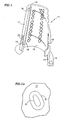
- Figures 1, 1 a, 2 and 2a display one possible embodiment of the present invention.
- the figures display a template 11 manufactured, for example, using stereo lithography (SLA) from a suitable material such as an extra clear resin.
- SLA stereo lithography
- the template 11 has a body 13 that generally corresponds to the shape of the object targeted for gross error evaluation.
- the shape of the body 13 could be determined from a solid model computer file of the object targeted for gross error evaluation.
- the body 13 has an interior surface 15 that faces the object and an exterior surface 17 that faces away from the object.
- the interior surface 15 includes a plurality of protuberances 19.
- the protuberances 19 contact the object, and keep the remainder of the body 13 offset from the surface of the object.
- the protuberances 19 preferably have a height that accommodates variation in object size without the remainder of the body 13 contacting the object.
- the location of the protuberances 19 could conform to a point system used during the manufacturing process.
- the body 13 has six protuberances 19 since the point system used during the manufacturing process identifies six points on the object.
- Figure 1a is a detailed view of the exterior surface 17 of the body 13.
- the exterior surface 17 preferably has one or more scribe lines 21 thereon. If formed during an SLA process, the scribe lines 21 could be grooves that extend a distance into the exterior surface 17 of the body 13.
- the present invention could utilize other suitable techniques to form the scribe lines 21.
- the scribe lines 21 could be printed indicia. In other words, the scribe lines are printed onto the exterior surface 17 of the body 13.
- the scribe lines 21 allow the user to evaluate the object, specifically a feature of the object, for gross errors. Accordingly, the scribes lines 21 are positioned on the exterior surface 17 so as to correspond to the location of such feature on the object. As shown in Figure 1a, the template could have two scribe lines 21 per feature. One scribe line 21 could identify a minimum of a tolerance range for the location of the feature on the object. The other scribe line 21 could identify a maximum of a tolerance range for the location of the feature on the object.
- the template 11 could also include printed indicia 23 to identify the object targeted for gross error evaluation.
- the printed indicia 23 could be the part number of the object targeted for gross error evaluation. Other manners of identifying the object targeted for gross error evaluation, however, could be used.
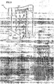
- FIGS 2 and 2a display one possible application of the template 11.
- the object targeted for gross error evaluation in the figure is a blade 50 of a gas turbine engine (not shown).
- the blade 50 includes a root section 51 for securing to a disc, an airfoil section 53 for converting the velocity of the fluid exiting the combustion section (not shown) of the engine into rotation of the disc, and a medial section 55 between the root section 51 and airfoil section 53.
- the manufacturing process for the blade 50 identifies points 57 thereon. Preferably, the manufacturing process identifies six points 57 on the blade 50.
- the airfoil section 53 can have apertures 59 in communication with a hollow interior (not shown). Cooling air (not shown) provided to the hollow interior exits the apertures 59 to provide film cooling to the blade 50.
- the template 11 allows the user to ensure, after the manufacture of the blade 50, that: (1) the apertures 59 exist on the suction side of the airfoil section 53 of the blade 50; and/or (2) the apertures 59 are properly located (i.e. within the tolerance range of the location of the feature on the object) on the suction side of the airfoil section 53 of the blade 50.
- the blade 50 receives the template 11.
- the protuberances 19 engage the blade 50 at the points 57 identified during the manufacturing process.
- Figure 2a displays a view through the template 11 with a properly located cooling hole 59 (the cooling hole 59 has been shown in phantom line to avoid confusion as the cooling hole 59 resides behind the clear template 11).
- the protuberances 19 keep the remainder of the body 13 of the template 11 away from the surface of the blade 50. The distance between the body 13 and the blade 50 is kept to a minimum to avoid parallax error.
- Figure 3 displays another possible embodiment of the present invention.
- the figure displays a template 111.
- the template 111 is preferably used to evaluate a different section of the object targeted for gross error evaluation. Save for a change in the hundreds digit, the reference characters identifying features of template 111 correspond to the reference characters identifying the same features of template 111.
- template 111 has a body 113 manufactured, for example, using stereo lithography (SLA) from a suitable material such as an extra clear resin.
- the body 113 generally corresponds to the shape of the object targeted for gross error evaluation.
- the body 113 has an interior surface 115 that faces the object and an exterior surface 117 that faces away from the object.
- the interior surface 15 includes a plurality of protuberances 119.
- the protuberances 119 contact the object, and keep the remainder of the body 113 offset from the surface of the object
- the protuberances 119 conform to a point system used during the manufacturing process.
- the template 111 has six protuberances 119.
- the exterior surface 117 of the body 113 preferably has one or more scribe lines 121 thereon. If formed during an SLA process, the scribe lines 121 could be grooves that extend a distance into the exterior surface 117 of the body 113. The present invention could utilize other suitable techniques to form the scribe lines 121. For example, the scribe lines 121 could be printed indicia. In other words, the scribe lines are printed onto the exterior surface 117 of the body 113.
- the scribe lines 121 allow the user to evaluate the object, specifically a feature of the object, for gross errors. Accordingly, the scribe lines 121 are positioned on the exterior surface 117 so as to correspond to the location of such feature on the object.
- the template 111 has two scribe lines 121 per feature. One scribe line 121 could identify a minimum of a tolerance range for the location of the feature on the object. The other scribe line 121 could identify a maximum of a tolerance range for the location of the feature on the object.
- the template 111 could also include printed indicia 123 to identify the object targeted for gross error evaluation.
- the printed indicia 123 could be the part number of the object targeted for gross error evaluation. Other manners of identifying the object targeted for gross error evaluation, however, could be used.
- Figure 4 displays the template 111 mounted on the blade 50.
- the template 111 allows the user to ensure, after the manufacture of the blade 50, that: (1) the apertures 59 exist on the pressure side of the airfoil section 53 of the blade 50; and/or (2) the apertures 59 are properly located (i.e. within the tolerance range of the location of the feature on the object) on the pressure side of the airfoil section 53 of the blade 50.
- the protuberances 119 engage the blade 50 at the points 57 identified during the manufacturing process. Comparing Figures 2 and 4 (note the figures show different sides of the blade), it is clear that the protuberances 119 contact the same points on the blade 50 as the protuberances 19 when using the template 11.
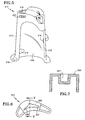
- Figures 5-7 display another possible embodiment of the present invention.
- the figures display a template 211.
- the template 211 is preferably used to evaluate a different section of the object targeted for gross error evaluation than templates 11, 111.
- the template 211 has features corresponding to the features of templates 11, 111. These features used the same reference character, save a change in the hundreds digit. Template 211 does have features different that those described with templates 11, 111. The features will have different reference characters.
- template 211 has a body 213 manufactured, for example, using stereo lithography (SLA) from a suitable material such as an extra clear resin.
- the body 213 generally corresponds to the shape of the object targeted for gross error evaluation.
- the body 213 has an interior surface 215 that faces the object and an exterior surface 217 that faces away from the object.
- the interior surface 215 includes a plurality of protuberances 219.
- the protuberances 219 conform to a point system used during the manufacturing process.
- the template 211 could also include printed indicia 223 to identify the object targeted for gross error evaluation.
- the printed indicia 223 could be the part number of the object targeted for gross error evaluation. Other manners of identifying the object targeted for gross error evaluation, however, could be used.
- the template 211 also includes a section 225 having a depressed area 227.
- the depressed area 227 has scallops 229 therein.
- the scallops 229 allow the user to evaluate the object, specifically features of the object, for gross errors. Accordingly, the scallops 229 are positioned on the depressed area 227 of the section 225 so as to correspond to the location of such features on the object.
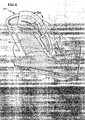
- Figure 8 displays the template 211 mounted on the blade 50.
- the template 211 allows the user to ensure, after the manufacture of the blade 50, that: (1) the apertures 59 exist on the radial tip of the airfoil section 53 of the blade 50; and/or (2) the apertures 59 are properly located (i.e. within the tolerance range of the location of the feature on the object) on the radial tip of the airfoil section 53 of the blade 50.
- Figure 8a shows
- the protuberances 119 engage the blade 50 at the points 57 identified during he manufacturing process. Comparing Figures 2 and 4 (note the figures show different sides of the blade), it is clear that the protuberances 119 contact the same points on the blade 50 as the protuberances 19 when using the template 11.
- Figure 8a displays a view through the template 211 with a properly located cooling hole 59 (the cooling hole 59 has been shown in phantom line to avoid confusion as the cooling hole 59 resides behind the clear template 211).
- the template 211 has five protuberances 219.
- the depressed area 227 serves as the sixth contact point with the blade 50.
- the location where depressed area 227 contacts blade 50 does not correspond to the sixth point location used with templates 11, 111. Nevertheless, the protuberances 219 and the depressed area 227 contact the object, and keep the remainder of the body 213 offset from the surface of the object.
Landscapes
- Physics & Mathematics (AREA)
- General Physics & Mathematics (AREA)
- Perforating, Stamping-Out Or Severing By Means Other Than Cutting (AREA)
- Length Measuring Devices By Optical Means (AREA)
- Instructional Devices (AREA)
- Injection Moulding Of Plastics Or The Like (AREA)
Abstract
Description
Claims (17)
- A template (11; 111; 211) for evaluating a part (50), comprising:wherein said element assists a user to determine whether said feature is at said desired location.a surface (15, 17; 115, 117; 215,217) having a shape corresponding to said part, andat least one element (21; 121; 229) on said surface corresponding to a desired location of a feature on said part;
- The template of claim 1, further comprising at least one protuberance (19; 119; 219) to contact said part (50).
- The template of claim 2, wherein said template (11; 111; 211) has at least five protuberances (19; 119; 219).
- The template of claim 3, wherein said template (11; 111; 211) has six protuberances (19; 119; 219).
- The template of any preceding claim, wherein said element comprises printed indicia.
- The template of any preceding claim, wherein said element comprises a scribe line (21; 121).
- The template of any preceding claim, wherein said element comprises a scallop (229).
- A method of evaluating a part (50), comprising the steps of:providing a template (11; 111; 211) having a shape corresponding to said part and at least one element (21; 121; 229) thereon corresponding to a desired location of a feature on said part;associating said template with said part; andusing said element to determine whether said feature is at said desired location.
- The method of claim 8, wherein said associating step comprises placing said template (11; 111; 211) against said part (50).
- The method of claim 9, wherein said template (11; 111; 211) further comprises at least one protuberance (19; 119; 219) to contact said part (50).
- The method of claim 10, wherein said template (11; 111; 211) has at least five protuberances (19; 119; 219).
- The method of claim 11, wherein said template (11; 111; 211) has six protuberances (19; 219; 219).
- The method of any of claims 8 to 12, wherein said determining step includes a step of viewing through said template (11; 111; 211).
- The method of any of claims 8 to 13, wherein said element comprises printed indicia.
- The method of any of claims 8 to 14, wherein said element comprises a scribe line (21; 121).
- The method of any of claims 8 to 15, wherein said element comprises a scallop (229).
- A template (11; 111; 211) for evaluating a part (50), comprising:wherein said element assists a user to determine whether said feature is at said desired location.a body having a shape corresponding to said part; andat least one element on said body corresponding to a desired location of a feature on said part;
Applications Claiming Priority (2)
| Application Number | Priority Date | Filing Date | Title |
|---|---|---|---|
| US55865004P | 2004-04-01 | 2004-04-01 | |
| US558650P | 2004-04-01 |
Publications (1)
| Publication Number | Publication Date |
|---|---|
| EP1582838A1 true EP1582838A1 (en) | 2005-10-05 |
Family
ID=34886348
Family Applications (1)
| Application Number | Title | Priority Date | Filing Date |
|---|---|---|---|
| EP05251995A Withdrawn EP1582838A1 (en) | 2004-04-01 | 2005-03-30 | Template for evaluating turbine blades |
Country Status (5)
| Country | Link |
|---|---|
| US (1) | US7024787B2 (en) |
| EP (1) | EP1582838A1 (en) |
| CN (1) | CN1677045A (en) |
| CA (1) | CA2500683A1 (en) |
| SG (1) | SG115805A1 (en) |
Cited By (7)
| Publication number | Priority date | Publication date | Assignee | Title |
|---|---|---|---|---|
| EP1988338A1 (en) * | 2007-04-30 | 2008-11-05 | General Electric Company | Systems and methods for installing cooling holes in a combustion liner |
| EP1843125A3 (en) * | 2006-04-07 | 2011-01-26 | United Technologies Corporation | System and method for locating features on an object |
| FR2987296A1 (en) * | 2012-02-23 | 2013-08-30 | Snecma | Control device for controlling cooling air discharge holes of gas turbine blade, has transparent sheet including reference marks whose number and arrangement are predefined according to number and location desired for air discharge holes |
| EP3524384A1 (en) * | 2018-02-09 | 2019-08-14 | United Technologies Corporation | Additively manufactured airflow mask tool |
| WO2023175281A1 (en) | 2022-03-18 | 2023-09-21 | Safran Aircraft Engines | Method for locating a mark on a turbomachine casing |
| WO2024149951A1 (en) * | 2023-01-12 | 2024-07-18 | Safran Aircraft Engines | Method for checking the compliance of an abradable coating in an outer casing of an aircraft turbojet engine |
| FR3165723A1 (en) * | 2024-08-26 | 2026-02-27 | Safran Aircraft Engines | METHOD AND DEVICE FOR CONTROLLING THE ROPE OF A TURBOMACHINE BLADE |
Families Citing this family (32)
| Publication number | Priority date | Publication date | Assignee | Title |
|---|---|---|---|---|
| US6910278B2 (en) * | 2003-01-30 | 2005-06-28 | Lockheed Martin Corporation | Apparatus and method for inspecting and marking repair areas on a blade |
| US8051564B2 (en) * | 2007-01-09 | 2011-11-08 | General Electric Company | Methods and apparatus for fabricating a turbine nozzle assembly |
| US7762004B2 (en) * | 2007-01-31 | 2010-07-27 | General Electric Company | Inspection tool for measuring bucket Z notch position |
| TWI317418B (en) * | 2007-03-01 | 2009-11-21 | Fu Kue Chang | A measuring method for the surface of a propeller |
| CN101458059A (en) * | 2007-12-13 | 2009-06-17 | 鸿富锦精密工业(深圳)有限公司 | Inspect tool |
| US7735238B2 (en) * | 2008-07-31 | 2010-06-15 | General Electric Company | Nozzle trailing edge position measurement and marking |
| US8609194B2 (en) * | 2010-01-21 | 2013-12-17 | Level 3 Inspection, Llc | Method and apparatus for composition coating for enhancing white light scanning of an object |
| CN102095351B (en) * | 2010-12-15 | 2012-06-20 | 武安市文祥合金制造有限公司 | Flat ruler and manufacturing method thereof |
| US8899115B2 (en) | 2011-04-20 | 2014-12-02 | United Technologies Corporation | Method and system for locating a laser vibrometer during non-contact scanning |
| US8621761B2 (en) * | 2011-12-30 | 2014-01-07 | United Technologies Corporation | Self identifying template gage probing system |
| US9567860B2 (en) | 2012-11-27 | 2017-02-14 | General Electric Company | Fixture for an airfoil shroud and method for modifying an airfoil shroud |
| US20160252420A1 (en) | 2013-10-18 | 2016-09-01 | United Technologies Corporation | Method and assembly for inspecting engine component |
| US9348001B2 (en) * | 2013-10-21 | 2016-05-24 | General Electric Company | Method and system for detecting surface features on turbine components |
| US9151587B2 (en) | 2013-11-11 | 2015-10-06 | General Electric Company | Bucket tip shroud measurement fixture and method of measuring bucket tip shroud orientation |
| US9611753B2 (en) | 2014-04-29 | 2017-04-04 | General Electric Company | Apparatus and method for inspecting a turbine blade tip shroud |
| DE102014106529B4 (en) * | 2014-05-09 | 2016-02-04 | Senvion Gmbh | Repair procedure for vortex generator and a kit for it |
| EP2998063B1 (en) * | 2014-09-16 | 2019-03-13 | Ansaldo Energia Switzerland AG | Tool for measuring geometrical parameters of a blade or vane in a turbomachine |
| US9933242B2 (en) * | 2014-09-22 | 2018-04-03 | Goodrich Corporation | Mistake proof contour gauge |
| EP3328592A4 (en) * | 2015-07-30 | 2019-01-23 | Sikorsky Aircraft Corporation | Locating positions on components |
| US9542739B1 (en) | 2015-08-12 | 2017-01-10 | General Electric Company | Virtual turbomachine blade contact gap inspection |
| US9733057B2 (en) * | 2015-09-25 | 2017-08-15 | The Boeing Company | Blind hole location tool |
| CN108072304B (en) * | 2016-11-16 | 2020-05-19 | 英业达科技有限公司 | A measuring jig dedicated to measuring the external dimensions of various blade servos |
| US10013752B2 (en) | 2016-11-18 | 2018-07-03 | General Electric Company | Virtual blade inspection |
| GB201700534D0 (en) * | 2017-01-12 | 2017-03-01 | Rolls Royce Plc | A method of measuring fan blade picture frame width |
| US10408091B2 (en) * | 2017-03-31 | 2019-09-10 | General Electric Company | Mounting apparatuses secured to turbine airfoils of turbine systems |
| US10570747B2 (en) * | 2017-10-02 | 2020-02-25 | DOOSAN Heavy Industries Construction Co., LTD | Enhanced film cooling system |
| EP3486010B1 (en) * | 2017-11-15 | 2025-08-13 | Airbus Operations, S.L. | Driling template |
| US10760889B2 (en) * | 2018-09-12 | 2020-09-01 | United Technologies Corporation | Fan blade masking/coating check inspection tool |
| FR3095507B1 (en) * | 2019-04-29 | 2021-04-16 | Safran Aircraft Engines | DIMENSIONAL CONTROL PROCESS OF A TURBOMACHINE PART |
| CN110879083A (en) * | 2019-12-17 | 2020-03-13 | 无锡市五十五度科技有限公司 | Cold plate inspection method |
| CN113218959A (en) * | 2020-01-21 | 2021-08-06 | 华晨宝马汽车有限公司 | Surface inspection tool and surface inspection method |
| US12468869B2 (en) * | 2022-03-23 | 2025-11-11 | Rtx Corporation | Inspection systems and methods with airfoil sheaths |
Citations (8)
| Publication number | Priority date | Publication date | Assignee | Title |
|---|---|---|---|---|
| US2202683A (en) * | 1937-04-29 | 1940-05-28 | Messerschmitt Boelkow Blohm | Testing of accuracy of workpiece dimensions |
| US2266535A (en) * | 1941-03-31 | 1941-12-16 | Compan Paul | Shield or mask for lipstick |
| US2270158A (en) * | 1939-02-09 | 1942-01-13 | Messerschmitt Boelkow Blohm | Templet |
| US3832785A (en) * | 1969-06-30 | 1974-09-03 | Gen Electric | Device for inspection of cambered airfoils |
| DE3611905A1 (en) * | 1986-04-09 | 1987-10-22 | Gematronik Gmbh | Method and device for testing the surface of a curved body |
| US6029333A (en) * | 1997-12-04 | 2000-02-29 | Ferco Tech Corporation | Method of making an inspection fixture for determining the accuracy of bent tubular parts |
| US20010023543A1 (en) * | 2000-02-02 | 2001-09-27 | Hastilow Neil K. | Conformance gauge |
| US20040148793A1 (en) * | 2003-01-30 | 2004-08-05 | Lockheed Martin Corporation | Apparatus and method for inspecting and marking repair areas on a blade |
Family Cites Families (14)
| Publication number | Priority date | Publication date | Assignee | Title |
|---|---|---|---|---|
| SU492681A1 (en) * | 1972-11-20 | 1975-11-25 | Специальное Конструкторско-Технологическое Бюро Герметических И Скважинных Насосов | Blade impeller assembly template |
| US4578875A (en) * | 1983-10-17 | 1986-04-01 | Vertin Thomas D | Checking gage model and method of making the same |
| DE3631153A1 (en) * | 1986-09-12 | 1988-03-24 | Mtu Muenchen Gmbh | TEST DEVICE FOR COMPONENTS |
| US5186190A (en) * | 1988-04-28 | 1993-02-16 | Hirzel Suzy C | Eyebrow stencil kit with alignment members |
| US5065518A (en) * | 1990-08-21 | 1991-11-19 | Herrera Michael L | Food product measuring device |
| FR2668408B1 (en) * | 1990-10-24 | 1993-01-22 | Aerospatiale | MARKING DEVICE FOR A FLAT SIDE AND A MACHINING SYSTEM USING THE SAME. |
| US5181325A (en) * | 1992-07-06 | 1993-01-26 | Gary Damon | System for duplicating bowling ball finger and thumb holes |
| US5390422A (en) * | 1993-06-11 | 1995-02-21 | Masco Corporation Of Indiana | Apparatus for aligning handle valves |
| DE4430526A1 (en) * | 1994-08-27 | 1995-01-19 | Voith Gmbh J M | Arrangement and method of orientating and checking turbine rotor blades |
| US5787598A (en) * | 1995-11-21 | 1998-08-04 | Anheuser-Busch, Inc. | Labeling equipment alignment tooling |
| US5666737A (en) * | 1995-12-19 | 1997-09-16 | Ryan, Iii; James C. | Template for european style cabinetry |
| TW402800B (en) * | 1999-02-12 | 2000-08-21 | Mosel Vitelic Inc | Chip brink washing wide observer |
| US6860211B2 (en) * | 2002-04-04 | 2005-03-01 | Michael A. Valeriote | Guide for making non-linear patterns using a long arm quilting machine |
| US6796051B2 (en) * | 2002-11-14 | 2004-09-28 | William Kent Trice | Drill marker tool |
-
2004
- 2004-07-23 US US10/898,694 patent/US7024787B2/en not_active Expired - Lifetime
-
2005
- 2005-03-14 CA CA002500683A patent/CA2500683A1/en not_active Abandoned
- 2005-03-29 SG SG200501874A patent/SG115805A1/en unknown
- 2005-03-30 EP EP05251995A patent/EP1582838A1/en not_active Withdrawn
- 2005-03-31 CN CNA2005100629635A patent/CN1677045A/en active Pending
Patent Citations (8)
| Publication number | Priority date | Publication date | Assignee | Title |
|---|---|---|---|---|
| US2202683A (en) * | 1937-04-29 | 1940-05-28 | Messerschmitt Boelkow Blohm | Testing of accuracy of workpiece dimensions |
| US2270158A (en) * | 1939-02-09 | 1942-01-13 | Messerschmitt Boelkow Blohm | Templet |
| US2266535A (en) * | 1941-03-31 | 1941-12-16 | Compan Paul | Shield or mask for lipstick |
| US3832785A (en) * | 1969-06-30 | 1974-09-03 | Gen Electric | Device for inspection of cambered airfoils |
| DE3611905A1 (en) * | 1986-04-09 | 1987-10-22 | Gematronik Gmbh | Method and device for testing the surface of a curved body |
| US6029333A (en) * | 1997-12-04 | 2000-02-29 | Ferco Tech Corporation | Method of making an inspection fixture for determining the accuracy of bent tubular parts |
| US20010023543A1 (en) * | 2000-02-02 | 2001-09-27 | Hastilow Neil K. | Conformance gauge |
| US20040148793A1 (en) * | 2003-01-30 | 2004-08-05 | Lockheed Martin Corporation | Apparatus and method for inspecting and marking repair areas on a blade |
Cited By (10)
| Publication number | Priority date | Publication date | Assignee | Title |
|---|---|---|---|---|
| EP1843125A3 (en) * | 2006-04-07 | 2011-01-26 | United Technologies Corporation | System and method for locating features on an object |
| EP1988338A1 (en) * | 2007-04-30 | 2008-11-05 | General Electric Company | Systems and methods for installing cooling holes in a combustion liner |
| FR2987296A1 (en) * | 2012-02-23 | 2013-08-30 | Snecma | Control device for controlling cooling air discharge holes of gas turbine blade, has transparent sheet including reference marks whose number and arrangement are predefined according to number and location desired for air discharge holes |
| EP3524384A1 (en) * | 2018-02-09 | 2019-08-14 | United Technologies Corporation | Additively manufactured airflow mask tool |
| US10760446B2 (en) | 2018-02-09 | 2020-09-01 | Raytheon Technologies Corporation | Additively manufactured airflow mask tool |
| WO2023175281A1 (en) | 2022-03-18 | 2023-09-21 | Safran Aircraft Engines | Method for locating a mark on a turbomachine casing |
| FR3133672A1 (en) * | 2022-03-18 | 2023-09-22 | Safran Aircraft Engines | METHOD FOR LOCALIZING A MARK ON A TURBOMACHINE CASING |
| WO2024149951A1 (en) * | 2023-01-12 | 2024-07-18 | Safran Aircraft Engines | Method for checking the compliance of an abradable coating in an outer casing of an aircraft turbojet engine |
| FR3145036A1 (en) * | 2023-01-12 | 2024-07-19 | Safran Aircraft Engines | Method for checking the conformity of an abradable coating in an aircraft turbojet outer casing |
| FR3165723A1 (en) * | 2024-08-26 | 2026-02-27 | Safran Aircraft Engines | METHOD AND DEVICE FOR CONTROLLING THE ROPE OF A TURBOMACHINE BLADE |
Also Published As
| Publication number | Publication date |
|---|---|
| US20050217131A1 (en) | 2005-10-06 |
| SG115805A1 (en) | 2005-10-28 |
| CA2500683A1 (en) | 2005-10-01 |
| CN1677045A (en) | 2005-10-05 |
| US7024787B2 (en) | 2006-04-11 |
Similar Documents
| Publication | Publication Date | Title |
|---|---|---|
| US7024787B2 (en) | Template for evaluating parts and method of using same | |
| TW200702905A (en) | Mask blank transparent substrate manufacturing method, mask blank manufacturing method, and exposure mask manufacturing method | |
| CN110691906B (en) | Protective housing with positioning mark | |
| EP1813773A3 (en) | Aerofoil assembly with improved vibration response and a method of manufacturing the aerofoil assembly | |
| WO2004059723A3 (en) | System to identify a wafer manufacturing problem and method therefor | |
| US20090324093A1 (en) | Method for comparing sectioned geometric data representations for selected objects | |
| JP2009115072A (en) | Method and fixture for manufacturing component parts | |
| GB2358829A (en) | A conformance gauge | |
| CN110113885B (en) | A kind of manufacturing method of FPC circuit board | |
| EP1982791A3 (en) | Manufacturing method for a hollow fan blade | |
| CN111988843B (en) | Base station self-calibration method | |
| JP3513569B2 (en) | Flexible printed circuit board and method of manufacturing the same | |
| US20230060415A1 (en) | Method for fabricating a wind turbine shell, wind turbine blade, wind turbine and method for repair of a wind turbine blade shell | |
| CN116878413B (en) | Preparation method of surface speckle of blisk blade | |
| CN113180865A (en) | Method for quickly drawing cutting line of three-dimensional dental model | |
| CN103009897B (en) | Method of fabricating advertisement words | |
| JP4914582B2 (en) | Visual component for vehicle instrument and method for manufacturing the same | |
| JP2023042812A (en) | Gasket with adhesive film, manufacturing method therefor and manufacturing method for member with gasket | |
| CN212886032U (en) | Cooling hole forming equipment | |
| CN113579665B (en) | Turbine blade processing method and cooling hole forming device | |
| CN119748875B (en) | A method, apparatus, and related equipment for determining printing compensation parameters. | |
| CN101494129A (en) | Method for manufacturing multi-layer color multi-group micropore metal panel | |
| US20090295796A1 (en) | Method of updating a model | |
| EP1777495A3 (en) | System and method for verifying the dimensions of airfoils | |
| CN221793055U (en) | Cutting die, punching device and punching production line |
Legal Events
| Date | Code | Title | Description |
|---|---|---|---|
| PUAI | Public reference made under article 153(3) epc to a published international application that has entered the european phase |
Free format text: ORIGINAL CODE: 0009012 |
|
| AK | Designated contracting states |
Kind code of ref document: A1 Designated state(s): AT BE BG CH CY CZ DE DK EE ES FI FR GB GR HU IE IS IT LI LT LU MC NL PL PT RO SE SI SK TR |
|
| AX | Request for extension of the european patent |
Extension state: AL BA HR LV MK YU |
|
| 17P | Request for examination filed |
Effective date: 20051006 |
|
| AKX | Designation fees paid |
Designated state(s): BE DE FR GB NL |
|
| 17Q | First examination report despatched |
Effective date: 20060919 |
|
| STAA | Information on the status of an ep patent application or granted ep patent |
Free format text: STATUS: THE APPLICATION IS DEEMED TO BE WITHDRAWN |
|
| 18D | Application deemed to be withdrawn |
Effective date: 20070130 |