EP1582730A1 - Apparatus for exhausting gases from gas turbine engines - Google Patents
Apparatus for exhausting gases from gas turbine engines Download PDFInfo
- Publication number
- EP1582730A1 EP1582730A1 EP05251595A EP05251595A EP1582730A1 EP 1582730 A1 EP1582730 A1 EP 1582730A1 EP 05251595 A EP05251595 A EP 05251595A EP 05251595 A EP05251595 A EP 05251595A EP 1582730 A1 EP1582730 A1 EP 1582730A1
- Authority
- EP
- European Patent Office
- Prior art keywords
- exhaust
- flow channel
- engine
- access door
- cowl
- Prior art date
- Legal status (The legal status is an assumption and is not a legal conclusion. Google has not performed a legal analysis and makes no representation as to the accuracy of the status listed.)
- Granted
Links
- 239000007789 gas Substances 0.000 title claims abstract description 76
- 230000001629 suppression Effects 0.000 claims abstract description 23
- 238000004891 communication Methods 0.000 claims abstract description 11
- 230000005465 channeling Effects 0.000 claims abstract description 8
- 238000001816 cooling Methods 0.000 claims description 32
- 238000002156 mixing Methods 0.000 claims description 19
- 239000003570 air Substances 0.000 claims description 18
- 239000012080 ambient air Substances 0.000 claims description 10
- 238000007599 discharging Methods 0.000 claims description 3
- 230000001939 inductive effect Effects 0.000 claims description 3
- 230000000712 assembly Effects 0.000 description 5
- 238000000429 assembly Methods 0.000 description 5
- 238000000034 method Methods 0.000 description 5
- 230000008878 coupling Effects 0.000 description 3
- 238000010168 coupling process Methods 0.000 description 3
- 238000005859 coupling reaction Methods 0.000 description 3
- 230000000694 effects Effects 0.000 description 3
- 230000008685 targeting Effects 0.000 description 3
- 230000005540 biological transmission Effects 0.000 description 2
- 230000000903 blocking effect Effects 0.000 description 2
- 239000011248 coating agent Substances 0.000 description 2
- 238000000576 coating method Methods 0.000 description 2
- 230000002708 enhancing effect Effects 0.000 description 2
- 238000009434 installation Methods 0.000 description 2
- 230000009467 reduction Effects 0.000 description 2
- 238000010008 shearing Methods 0.000 description 2
- 230000008859 change Effects 0.000 description 1
- 230000003247 decreasing effect Effects 0.000 description 1
- 230000005670 electromagnetic radiation Effects 0.000 description 1
- 238000010438 heat treatment Methods 0.000 description 1
- 238000003331 infrared imaging Methods 0.000 description 1
- 238000007689 inspection Methods 0.000 description 1
- 238000012423 maintenance Methods 0.000 description 1
- 239000002184 metal Substances 0.000 description 1
- 230000001737 promoting effect Effects 0.000 description 1
- 230000003068 static effect Effects 0.000 description 1
- 230000007704 transition Effects 0.000 description 1
- 238000011144 upstream manufacturing Methods 0.000 description 1
Images



Classifications
-
- F—MECHANICAL ENGINEERING; LIGHTING; HEATING; WEAPONS; BLASTING
- F02—COMBUSTION ENGINES; HOT-GAS OR COMBUSTION-PRODUCT ENGINE PLANTS
- F02K—JET-PROPULSION PLANTS
- F02K1/00—Plants characterised by the form or arrangement of the jet pipe or nozzle; Jet pipes or nozzles peculiar thereto
- F02K1/78—Other construction of jet pipes
- F02K1/82—Jet pipe walls, e.g. liners
- F02K1/822—Heat insulating structures or liners, cooling arrangements, e.g. post combustion liners; Infrared radiation suppressors
- F02K1/825—Infrared radiation suppressors
-
- B—PERFORMING OPERATIONS; TRANSPORTING
- B64—AIRCRAFT; AVIATION; COSMONAUTICS
- B64D—EQUIPMENT FOR FITTING IN OR TO AIRCRAFT; FLIGHT SUITS; PARACHUTES; ARRANGEMENT OR MOUNTING OF POWER PLANTS OR PROPULSION TRANSMISSIONS IN AIRCRAFT
- B64D33/00—Arrangement in aircraft of power plant parts or auxiliaries not otherwise provided for
- B64D33/04—Arrangement in aircraft of power plant parts or auxiliaries not otherwise provided for of exhaust outlets or jet pipes
-
- B—PERFORMING OPERATIONS; TRANSPORTING
- B64—AIRCRAFT; AVIATION; COSMONAUTICS
- B64D—EQUIPMENT FOR FITTING IN OR TO AIRCRAFT; FLIGHT SUITS; PARACHUTES; ARRANGEMENT OR MOUNTING OF POWER PLANTS OR PROPULSION TRANSMISSIONS IN AIRCRAFT
- B64D33/00—Arrangement in aircraft of power plant parts or auxiliaries not otherwise provided for
- B64D33/04—Arrangement in aircraft of power plant parts or auxiliaries not otherwise provided for of exhaust outlets or jet pipes
- B64D2033/045—Arrangement in aircraft of power plant parts or auxiliaries not otherwise provided for of exhaust outlets or jet pipes comprising infrared suppressors
Definitions
- This invention relates generally to gas turbine engines, and more specifically to methods and apparatus for exhausting gases from gas turbine engines.
- the exhaust nozzle and plume from gas turbine engines is a potential source of high infrared energy which may be used for targeting and/or tracking purposes. More specifically, the infrared energy may be used for targeting and/or tracking by heat seeking missiles and/or various forms of infrared imaging systems. Because the military mission of helicopters may involve flying at low altitudes and at reduced speed in comparison to other military aircraft, helicopters are susceptible to ground-to-air, infrared-guided missiles. For example, within at least some known helicopters, the exposed metal surfaces of the gas turbine engine exhaust may operate in excess of 800°F, and thus emit infrared electromagnetic radiation at virtually all wavelengths as hot exhaust gases flow past the exposed surfaces. Moreover, continued heating of aircraft surfaces, including the fuselage, during hover or flight may also create structural issues.
- infrared signature reduction methods have been employed to facilitate reducing the infrared signature of a gas turbine engine. More specifically, at least some known gas turbine engines use complicated cooling schemes to supply cooling air to facilitate cooling directly visible surfaces and to dilute the high temperature exhaust gases. Other known gas turbine engines use infrared suppressors which change the direction of the exhaust flow discharged from the engine to facilitate hiding the hottest exposed surfaces with cooler surfaces.
- any benefits gained by such systems may be offset by losses created in acquiring the reduced infrared signature. More specifically, when the exhaust gases are cooled by cooling air, the air may be provided at a substantial engine power loss or weight penalty. Furthermore, in other known systems, the benefits gained by such systems may be offset by comparatively large installation space requirements, complex ducting, and/or substantial weight penalties. Moreover, the weight and physical size of such suppression systems may limit access to the gas turbine engine for routine maintenance and inspections.
- a method for assembling a gas turbine engine comprises mounting a core engine to a vehicle, coupling a fuselage radially outward and around the core engine, and coupling an exhaust nozzle to the core engine to channel exhaust gases discharged from the core engine.
- the method also comprises coupling an infrared suppression system in flow communication with the engine exhaust nozzle for channeling exhaust gases discharged from said exhaust nozzle to facilitate suppressing an exhaust infrared signature of the core engine during operation, wherein the infrared suppression system includes an access door and a flow channel that is coupled to the access door such that the flow channel is movable with the access door from a closed position to an open position.
- an exhaust assembly for a gas turbine engine including a turbine rear frame includes an engine exhaust nozzle extending downstream from the turbine rear frame, and an infrared suppression system coupled in flow communication with the engine exhaust nozzle for channeling exhaust gases discharged from the exhaust nozzle.
- the suppression system includes a flow channel coupled to an access door, such that the flow channel is movable with the access door from a closed position to an open position wherein the access door forms a work platform configured to support a user thereon.
- the suppression system facilitates suppressing an exhaust infrared signature of the gas turbine engine.
- a gas turbine engine configured to couple to a fuselage.
- the gas turbine engine includes a core engine and an exhaust assembly that extends downstream from the core engine for discharging exhaust gases from the core engine.
- the exhaust assembly includes an exhaust nozzle that is coupled to the core engine and an infrared suppression system that is coupled in flow communication downstream from the engine exhaust nozzle for channeling exhaust gases discharged from the exhaust nozzle.
- the infrared suppression system includes a flow channel and an access door. The flow channel is coupled to the access door, such that the flow channel is movable with the access door from a closed position to an open position. Both the flow channel and access door are coupled to the fuselage.
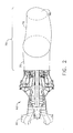
- Figure 1 is a plan view of a helicopter 10 that includes two gas turbine engine assemblies 42 and access doors 12.
- Figure 2 is a perspective view of a core engine 40 and exhaust nozzle 76 that may be used with gas turbine engine assembly 42.
- Figure 3 is a partial front view of an exemplary helicopter 14 including access door 12 shown in a closed position 16.
- Figure 4 is a partial front view of helicopter 14 including access door 12 shown in an open position 22.
- Figures 5, 6, and 7 are alternative embodiments of turbine exhaust nozzles 76 that may be used with gas turbine engine assembly 42.
- helicopter 14 includes a pair of gas turbine engines 40 that each include an inlet end 44 and an exhaust end 46.
- Engines 40 are symmetrical with respect to an axis of symmetry 47 extending between engines 40.
- Core engines 40 are mounted within an engine compartment 48 defined by a helicopter fuselage 50.
- gas turbine engine assembly 42 includes core engines 40 and an exhaust assembly 52 that extends downstream from engines 40 for discharging exhaust gases from engines 40.
- each core engine 40 is a T58 engine commercially available from General Electric Aircraft Engines, Lynn, Massachusetts.
- a rear drive shaft 60 extends from engine 40 to a main transmission 62.
- Exhaust assembly 52 includes a pair of exhaust nozzle assemblies 70 and suppression system 72.
- Suppression system 72 facilitates suppressing an exhaust infrared signature of gas turbine engine assembly 42 during engine operation.
- suppression mean that the infrared signature emanating from gas turbine engine assembly 10 is facilitated to be reduced below a pre-determined threshold value which is indicative of the acquisition, tracking, and/or targeting capability of a particular infrared threat.
- Each exhaust nozzle assembly 70 includes a turbine rear frame housing 75 that includes a drive shaft tunnel 74, and a primary nozzle 76. Specifically, exhaust discharged from each engine 40 is initially channeled through rear frame housing 75 and around drive shaft tunnel 74 prior to entering primary nozzle 76.
- each drive shaft tunnel 74 is integrally formed with an elbow 78 such that exhaust entering each rear frame 75 is discharged outwardly at an oblique angle ⁇ measured with respect to axis of symmetry 47. More specifically, in the exemplary embodiment, angle ⁇ is approximately sixty degrees.
- each primary nozzle is a single-wall nozzle that includes an elbow 82.
- Elbow 82 causes the direction of exhaust flowing through nozzle 76 to be discharged in a direction that is substantially parallel to centerline axis of symmetry 47.
- a length L N of primary nozzle 76 measured between an inlet end 84 and a discharge end 86 that is downstream from inlet end 84, is variably selected to enable flow to be discharged substantially axially therefrom.
- nozzle length L N ensures that an exit aperture defined at nozzle discharge end 86 is oriented substantially perpendicularly to a direction of exhaust flow discharged therethrough.
- elbow 82 and nozzle length L N causes nozzle 76 to extend through fuselage 50 such that exhaust discharged from nozzle 76 is accelerated and then discharged adjacent an external surface 98 of fuselage 50.
- flow through rear frame 75 and primary nozzles 76 remains substantially axial, as neither rear frame 75 and/or primary nozzles 76 include respective elbows 78 and 82.
- a cross-sectional area defined of the nozzle exit aperture defined at discharge end 86 may be any cross-sectional shape that enables nozzle 76 to function as describe herein. More specifically, the nozzle exit aperture facilitates inducing mixing of exhaust flow discharged therefrom, without promoting an outward propagation of exhaust gases discharged therefrom.
- the nozzle exit aperture cross-sectional area may be, but is not limited to being, circular, elliptical, rectangular, or daisy-shaped.
- discharge end 86 may also include other mixing enhancement features such as, but not limited to, lobes, scalloped edges, turbulators, and/or chevrons.
- discharge end 86 includes a convergent lobe design which facilitates mixing exhaust gases discharged therethrough with ambient cooling air introduced to gas turbine engine assembly 10, as described in more detail below.
- Exhaust exiting primary nozzles 76 is channeled into suppression system 72.
- Suppression system 72 includes a pair of flow channels 90 that are each coupled to an access door 12. More specifically, in the exemplary embodiment, flow channel 90 is formed integrally with door 12. Each flow channel 90 is coupled in flow communication with primary nozzles 76 such that flow exiting nozzles 76 is routed through flow channels 90 before being discharged to the atmosphere. More specifically, a cross-sectional area of each flow channel is selected to form an annulus with each respective primary nozzle 76, such that flow exiting nozzles 76 forms a venturi effect which creates a local low pressure immediately downstream from each nozzle discharge end 86.
- each flow channel 90 is tapered from an inlet end 12 coupled to primary nozzle 76, through an exit aperture or discharge end 94. More specifically, in the exemplary embodiment, flow channel 90 is tapered such that a cross-sectional area defined within flow channel 90 by an inner surface 96 of flow channel 90 is progressively decreased from inlet end 12 to discharge end 94. Accordingly, the tapering facilitates ensuring a constant exhaust flow path velocity is maintained within flow channel 90.
- the cross-sectional area defined within flow channel 90 may be any cross-sectional shape that enables flow channel 90 to function as described herein, such as, but not limited to substantially circular, elliptical, or square.
- discharge end 94 is formed with a substantially rectangular cross-sectional profile, and as such, in the exemplary embodiment, the cross-sectional shape of flow channel 90 varies along a length L C of flow channel 90 to facilitate providing a smooth transition from inlet end 12 to discharge end 94.
- the variable cross-sectional area of flow channel 90 also facilitates optimizing engine back-pressure within gas turbine engine assembly 42, while providing a reduced cooling slot exit static pressure to facilitate achieving a desired cooling flow, as described in more detail below. Accordingly, by optimizing system back-pressure, flow channel 90 also facilitates maintaining a desired engine operating efficiency.
- Each flow channel L C is measured between inlet and exit ends 12 and 94, respectively.
- Channel length L C ensures that exhaust discharged from core engines 40 is discharged downstream from, and does not impinge upon, transmission 62.
- Channel length L C also facilitates mixing between exhaust discharged from core engine 40 and ambient cooling air introduced to each flow channel 90, as described in more detail below, to facilitate reducing an operating temperature of exhaust flowing therethrough.
- the exact channel length L C is a function of a plurality of parameters, including, but not limited to, the particular installation, available power penalty, and desired infrared and radar cross-sectional reduction goals.
- each flow channel 90 also includes a plurality of cooling baffles 100, cooling slots 104, and an aft elbow 102.
- Elbow 102 changes a direction of exhaust flowing through flow channel 90, such that exhaust entering each flow channel 90 is discharged outwardly with respect to axis of symmetry 47 to facilitate preventing the exhaust gases from impinging against, or contacting, fuselage 50.
- Cooling slots 104 extend between flow channel inner surface 96 and an outer surface 106 of flow channel 90 to facilitate admitting cooling air into flow channel 90.
- Slots 104 are aft facing such that exhaust gases entering flow channel 90 are prevented from exiting flow channel 90 through slots 100. More specifically, air entering slots 104 forms a cooling boundary layer to facilitate cooling those portions of flow channel inner surface 96 that are directly visible through flow channel exit aperture 94. Accordingly, the combination of exit aperture 94, flow channel length L C , and elbow 102 facilitate obstructing or preventing direct line-of-sight viewing of uncooled portions of flow channel inner surface 96 through exit aperture 94.
- at least a portion of flow channel inner surface 96 is coated with a high emissivity coating to substantially prevent infrared reflections through exit aperture 94 that may be emitted or originate from hotter "hidden" surfaces.
- channel inner surface 96 includes a surface characteristic that substantially prevents infrared reflections through exit aperture 94 that may be emitted or originate from hotter "hidden” surfaces.
- Cowl 120 is coupled around primary nozzles 76 and flow channels 90 such that at least one cooling passage 126 is defined between an inner surface 128 of cowl 120 and nozzles and flow channels 76 and 90, respectively. More specifically, cooling passage 126 is coupled in flow communication with flow channel slots 100. Moreover, cowl 120 facilitates preventing hot surfaces extending over nozzles 76 and flow channels 90 from emitting infrared signals radially outwardly.
- Cowl 120 includes a fairing or boat tail portion 122 and an inlet mixing portion 124. Boat tail portion 122 extends between fuselage 50 and flow channel elbow 102 to provide structural support to flow channel 90. In the exemplary embodiment, boat tail portion 122 is tapered to a thin trailing edge 126 to facilitate reducing drag during flight operations.
- Cowl mixing portion 124 includes a plurality openings 130 that are defined along an upstream side 132 of cowl 120.
- cowl mixing portion 124 includes only one opening 130.
- openings 130 are generally forward facing to prevent exhaust gases from being discharged therethrough, and such that openings 130 function as a ram air scoop to enable ambient air to be admitted via a ram effect, or through natural flow, into primary nozzles 76 and flow channels 90.
- Ambient air channeled through openings 130 facilitates annulus mixing and flow channel cooling. More specifically, a portion of ambient air entering openings 130, represented by arrow 140, is channeled into an annulus surrounding primary nozzles 76, and the remaining ambient air entering openings 130, represented by arrow 142, is channeled into cooling passage 126 and channeled to cooling slots 100. Air 140 is directed into the annulus surrounding primary nozzles 76 to facilitate mixing with exhaust gases discharged from primary nozzles 76.
- cowl inner surface 128 is coated with a high emissivity coating to substantially prevent infrared reflections through exit aperture that may be emitted or originate from higher temperature surfaces.
- cowl inner surface 128 includes a surface characteristic that substantially prevents infrared reflections through openings 130 that may be emitted or originate from higher temperature surfaces.
- Flow channels 90 are each coupled to access door 12, and as such, are moveable with access door 12 between open position 22 and closed position 16. More specifically, when access door 12 is in closed position 16, flow channel 90 is coupled in position to capture exhaust flow discharged from primary nozzles 76, as described above. However, during helicopter non-flight operations, because access door 12 is hingedly coupled to fuselage 50, access door 12 may be rotated from closed position 16 to open position 22 to provide access to components within gas turbine engine assembly 10. Moreover, as door 12 is rotated to open position 22 from closed position 16, flow channel 90 and cowl 120 are each moved with door 12, while primary nozzle 76 remains coupled in position to engine rear housing 75. Accordingly, primary nozzle 76, flow channel 90, blocking panel 150, and cowl 120 are designed for clearance to enable door 12 to be opened, yet retain suppressor flow functionality when door 12 is closed.
- flow channel 90 includes a plurality of hollow baffles which are internally cooled.
- the baffles are positioned across the flowpath defined within flow channel 90 such that the baffles actually define a plurality of flowpath passages through flow channel 90.
- exhaust flowing past the baffles is convectively cooled.
- access door 12 is substantially rectangular, and includes a substantially planar inner surface 160. Accordingly, when rotated to open position 22, planar surface 160 extends substantially perpendicularly from fuselage 50 and is substantially parallel to the ground beneath helicopter 14. Moreover, when access door 12 is in open position 22, access door 12 is fabricated with enough strength to support a user on inner surface 160, and as such, may be used as a work platform.
- cooling air is supplied to gas turbine engine assembly 10 through cowl openings 130.
- a portion 140 of such ambient air is channeled into the annulus surrounding primary nozzles 76 to facilitate reducing an operating temperature of external surfaces of primary nozzles 76.
- the low pressure area created by the venturi effect created as exhaust flow exits primary nozzles 76 facilitates drawing additional ambient air 140 into the channel extending downstream from primary nozzles 76.
- the nozzle exit aperture defined at discharge end 86 facilitates inducing mixing of ambient cooling air 140 and exhaust gases discharged from core engine 40 such that hot exhaust gases at primary nozzle discharge end 86 are facilitated to be suppressed.
- the mixing enhancement features included at nozzle discharge end 86 facilitate enhancing shearing and mixing between exhaust and ambient air flows.
- a portion 142 of such ambient air is channeled through passage 126 and to slots 100, during operation, wherein remaining air 142 entering flow channel 90 provides a layer of cooling air to facilitate cooling aft portions of flow channel inner surface 96 that are visible through exit aperture 94.
- slots 100 facilitate reducing an operating temperature of exhaust flow path surfaces. Additional suppression is achieved through the combination of exit aperture 94, flow channel length L c , and elbow 102, which facilitate obstructing or preventing direct line-of-sight viewing of uncooled portions of flow channel inner surface 96 through exit aperture 94. Accordingly, suppression system 72 facilitates the operating temperature of engine exhaust through gas turbine engine assembly 10, thus suppressing the infrared signature generated by core engines 40.
- flow exit aperture 86 of primary nozzle 76 has either a substantially circular cross-sectional profile or a substantially elliptical cross-sectional profile.
- exit aperture 86 may have any cross-sectional profile that enables primary nozzle 76 to function as described herein.
- nozzle exit aperture 86 facilitates enhances mixing of ambient cooling air 140 and exhaust gases discharged from core engine 40 using chevron-shaped extensions of primary nozzle 76.
- each chevron-shaped extension is cup- or spoon-shaped and includes a concave surface that faces inwardly towards the hot primary nozzle exhaust flow.
- nozzle exit aperture 86 is substantially rectangular in cross-section and facilitates enhances mixing of ambient cooling air 140 and exhaust gases discharged from core engine 40 via corrugated surfaces of primary nozzle 76.
- each corrugation is aligned such that the axis of corrugation extends substantially in the same direction as that of the hot primary nozzle exhaust flow.
- the enhanced mixing may be accomplished with or with out the use of corrugations and regardless of the cross-sectional shape of nozzle 76 adjacent aperture 86.
- nozzle 76 has a substantially circular cross sectional profile adjacent exit aperture 86 and includes a plurality of corrugations.
- Each assembly includes a exhaust assembly that facilitates suppressing an infrared signature generated by the core engines.
- the exhaust assembly initially turns and accelerates the exhaust prior to mixing the exhaust with an ambient airflow. Additional cooling air facilitates cooling flowpath surfaces that are visible through the exhaust assembly discharge.
- the exhaust assembly system facilitates suppressing an infrared signature of the engine in a cost-effective and reliable manner.
- gas turbine assemblies are described above in detail.
- the assemblies are not limited to the specific embodiments described herein, but rather, components of each assembly may be utilized independently and separately from other components described herein.
- Each gas turbine engine assembly component can also be used in combination with other gas turbine engine assembly components.
Landscapes
- Engineering & Computer Science (AREA)
- Chemical & Material Sciences (AREA)
- Combustion & Propulsion (AREA)
- Mechanical Engineering (AREA)
- General Engineering & Computer Science (AREA)
- Aviation & Aerospace Engineering (AREA)
- Exhaust Silencers (AREA)
Abstract
Description
- This invention relates generally to gas turbine engines, and more specifically to methods and apparatus for exhausting gases from gas turbine engines.
- The exhaust nozzle and plume from gas turbine engines is a potential source of high infrared energy which may be used for targeting and/or tracking purposes. More specifically, the infrared energy may be used for targeting and/or tracking by heat seeking missiles and/or various forms of infrared imaging systems. Because the military mission of helicopters may involve flying at low altitudes and at reduced speed in comparison to other military aircraft, helicopters are susceptible to ground-to-air, infrared-guided missiles. For example, within at least some known helicopters, the exposed metal surfaces of the gas turbine engine exhaust may operate in excess of 800°F, and thus emit infrared electromagnetic radiation at virtually all wavelengths as hot exhaust gases flow past the exposed surfaces. Moreover, continued heating of aircraft surfaces, including the fuselage, during hover or flight may also create structural issues.
- Accordingly, within at least some known gas turbine engines, infrared signature reduction methods have been employed to facilitate reducing the infrared signature of a gas turbine engine. More specifically, at least some known gas turbine engines use complicated cooling schemes to supply cooling air to facilitate cooling directly visible surfaces and to dilute the high temperature exhaust gases. Other known gas turbine engines use infrared suppressors which change the direction of the exhaust flow discharged from the engine to facilitate hiding the hottest exposed surfaces with cooler surfaces.
- However, generally, any benefits gained by such systems may be offset by losses created in acquiring the reduced infrared signature. More specifically, when the exhaust gases are cooled by cooling air, the air may be provided at a substantial engine power loss or weight penalty. Furthermore, in other known systems, the benefits gained by such systems may be offset by comparatively large installation space requirements, complex ducting, and/or substantial weight penalties. Moreover, the weight and physical size of such suppression systems may limit access to the gas turbine engine for routine maintenance and inspections.
- In one aspect of the invention, a method for assembling a gas turbine engine is provided. The method comprises mounting a core engine to a vehicle, coupling a fuselage radially outward and around the core engine, and coupling an exhaust nozzle to the core engine to channel exhaust gases discharged from the core engine. In addition, the method also comprises coupling an infrared suppression system in flow communication with the engine exhaust nozzle for channeling exhaust gases discharged from said exhaust nozzle to facilitate suppressing an exhaust infrared signature of the core engine during operation, wherein the infrared suppression system includes an access door and a flow channel that is coupled to the access door such that the flow channel is movable with the access door from a closed position to an open position.
- In another aspect, an exhaust assembly for a gas turbine engine including a turbine rear frame is provided. The exhaust assembly includes an engine exhaust nozzle extending downstream from the turbine rear frame, and an infrared suppression system coupled in flow communication with the engine exhaust nozzle for channeling exhaust gases discharged from the exhaust nozzle. The suppression system includes a flow channel coupled to an access door, such that the flow channel is movable with the access door from a closed position to an open position wherein the access door forms a work platform configured to support a user thereon. The suppression system facilitates suppressing an exhaust infrared signature of the gas turbine engine.
- In a further aspect, a gas turbine engine configured to couple to a fuselage is provided. The gas turbine engine includes a core engine and an exhaust assembly that extends downstream from the core engine for discharging exhaust gases from the core engine. The exhaust assembly includes an exhaust nozzle that is coupled to the core engine and an infrared suppression system that is coupled in flow communication downstream from the engine exhaust nozzle for channeling exhaust gases discharged from the exhaust nozzle. The infrared suppression system includes a flow channel and an access door. The flow channel is coupled to the access door, such that the flow channel is movable with the access door from a closed position to an open position. Both the flow channel and access door are coupled to the fuselage.
- The invention will now be described in greater detail, by way of example, with reference to the drawings, in which:-
- Figure 1 is a plan view of a gas turbine engine assembly including an access door that may be used with a helicopter;
- Figure 2 is a perspective view of a core engine and an exemplary exhaust nozzle that may be used with the gas turbine engine assembly shown in Figure 1;
- Figure 3 is a partial front view of an exemplary helicopter including the access door shown in Figure 1 in a closed position;
- Figure 4 is a partial front view of the helicopter shown in Figure 3 including the access door shown in Figure 1 in an open position;
- Figure 5 is an alternative embodiment of a turbine exhaust nozzle that may be used with the gas turbine engine assembly shown in Figure 1;
- Figure 6 is another alternative embodiment of an exemplary turbine exhaust nozzle that may be used with the gas turbine engine assembly shown in Figure 1; and
- Figure 7 is a further alternative embodiment of an exemplary turbine exhaust nozzle that may be used with the gas turbine engine assembly shown in Figure 1.
-
- Figure 1 is a plan view of a
helicopter 10 that includes two gasturbine engine assemblies 42 andaccess doors 12. Figure 2 is a perspective view of acore engine 40 andexhaust nozzle 76 that may be used with gasturbine engine assembly 42. Figure 3 is a partial front view of anexemplary helicopter 14 includingaccess door 12 shown in a closedposition 16. Figure 4 is a partial front view ofhelicopter 14 includingaccess door 12 shown in anopen position 22. Figures 5, 6, and 7 are alternative embodiments ofturbine exhaust nozzles 76 that may be used with gasturbine engine assembly 42. - In the exemplary embodiment,
helicopter 14 includes a pair ofgas turbine engines 40 that each include aninlet end 44 and anexhaust end 46.Engines 40 are symmetrical with respect to an axis ofsymmetry 47 extending betweenengines 40.Core engines 40 are mounted within anengine compartment 48 defined by ahelicopter fuselage 50. Specifically, in the exemplary embodiment, gasturbine engine assembly 42 includescore engines 40 and anexhaust assembly 52 that extends downstream fromengines 40 for discharging exhaust gases fromengines 40. In one embodiment, eachcore engine 40 is a T58 engine commercially available from General Electric Aircraft Engines, Lynn, Massachusetts. A rear drive shaft 60 extends fromengine 40 to amain transmission 62. -
Exhaust assembly 52 includes a pair ofexhaust nozzle assemblies 70 andsuppression system 72.Suppression system 72, as described in more detail below, facilitates suppressing an exhaust infrared signature of gasturbine engine assembly 42 during engine operation. As used herein, the term suppression mean that the infrared signature emanating from gasturbine engine assembly 10 is facilitated to be reduced below a pre-determined threshold value which is indicative of the acquisition, tracking, and/or targeting capability of a particular infrared threat. - Each
exhaust nozzle assembly 70 includes a turbinerear frame housing 75 that includes adrive shaft tunnel 74, and aprimary nozzle 76. Specifically, exhaust discharged from eachengine 40 is initially channeled throughrear frame housing 75 and arounddrive shaft tunnel 74 prior to enteringprimary nozzle 76. In the exemplary embodiment, eachdrive shaft tunnel 74 is integrally formed with anelbow 78 such that exhaust entering eachrear frame 75 is discharged outwardly at an oblique angle measured with respect to axis ofsymmetry 47. More specifically, in the exemplary embodiment, angle is approximately sixty degrees. - Exhaust discharged from
engines 40 is channeled into a pair ofprimary nozzles 76 that are each coupled to turbinerear frame housing 75. In the exemplary embodiment, each primary nozzle is a single-wall nozzle that includes anelbow 82. Elbow 82 causes the direction of exhaust flowing throughnozzle 76 to be discharged in a direction that is substantially parallel to centerline axis ofsymmetry 47. Accordingly, a length LN ofprimary nozzle 76, measured between aninlet end 84 and adischarge end 86 that is downstream frominlet end 84, is variably selected to enable flow to be discharged substantially axially therefrom. Moreover, nozzle length LN ensures that an exit aperture defined atnozzle discharge end 86 is oriented substantially perpendicularly to a direction of exhaust flow discharged therethrough. In addition, the combination ofelbow 82 and nozzle length LN causesnozzle 76 to extend throughfuselage 50 such that exhaust discharged fromnozzle 76 is accelerated and then discharged adjacent anexternal surface 98 offuselage 50. In an alternative embodiment, depending on the application of gasturbine engine assembly 10, flow throughrear frame 75 andprimary nozzles 76 remains substantially axial, as neitherrear frame 75 and/orprimary nozzles 76 includerespective elbows - A cross-sectional area defined of the nozzle exit aperture defined at
discharge end 86 may be any cross-sectional shape that enablesnozzle 76 to function as describe herein. More specifically, the nozzle exit aperture facilitates inducing mixing of exhaust flow discharged therefrom, without promoting an outward propagation of exhaust gases discharged therefrom. For example, as shown in Figures 5 and 6, the nozzle exit aperture cross-sectional area may be, but is not limited to being, circular, elliptical, rectangular, or daisy-shaped. Additionally,discharge end 86 may also include other mixing enhancement features such as, but not limited to, lobes, scalloped edges, turbulators, and/or chevrons. Moreover, in another alternative embodiment,discharge end 86 includes a convergent lobe design which facilitates mixing exhaust gases discharged therethrough with ambient cooling air introduced to gasturbine engine assembly 10, as described in more detail below. - Exhaust exiting
primary nozzles 76 is channeled intosuppression system 72.Suppression system 72 includes a pair offlow channels 90 that are each coupled to anaccess door 12. More specifically, in the exemplary embodiment, flowchannel 90 is formed integrally withdoor 12. Eachflow channel 90 is coupled in flow communication withprimary nozzles 76 such thatflow exiting nozzles 76 is routed throughflow channels 90 before being discharged to the atmosphere. More specifically, a cross-sectional area of each flow channel is selected to form an annulus with each respectiveprimary nozzle 76, such thatflow exiting nozzles 76 forms a venturi effect which creates a local low pressure immediately downstream from eachnozzle discharge end 86. Accordingly, in one embodiment, eachflow channel 90 is tapered from aninlet end 12 coupled toprimary nozzle 76, through an exit aperture or dischargeend 94. More specifically, in the exemplary embodiment, flowchannel 90 is tapered such that a cross-sectional area defined withinflow channel 90 by aninner surface 96 offlow channel 90 is progressively decreased frominlet end 12 to dischargeend 94. Accordingly, the tapering facilitates ensuring a constant exhaust flow path velocity is maintained withinflow channel 90. - The cross-sectional area defined within
flow channel 90 may be any cross-sectional shape that enablesflow channel 90 to function as described herein, such as, but not limited to substantially circular, elliptical, or square. In addition, in the exemplary embodiment, dischargeend 94 is formed with a substantially rectangular cross-sectional profile, and as such, in the exemplary embodiment, the cross-sectional shape offlow channel 90 varies along a length LC offlow channel 90 to facilitate providing a smooth transition frominlet end 12 to dischargeend 94. Moreover, the variable cross-sectional area offlow channel 90 also facilitates optimizing engine back-pressure within gasturbine engine assembly 42, while providing a reduced cooling slot exit static pressure to facilitate achieving a desired cooling flow, as described in more detail below. Accordingly, by optimizing system back-pressure,flow channel 90 also facilitates maintaining a desired engine operating efficiency. - Each flow channel LC is measured between inlet and exit ends 12 and 94, respectively. Channel length LC ensures that exhaust discharged from
core engines 40 is discharged downstream from, and does not impinge upon,transmission 62. Channel length LC also facilitates mixing between exhaust discharged fromcore engine 40 and ambient cooling air introduced to eachflow channel 90, as described in more detail below, to facilitate reducing an operating temperature of exhaust flowing therethrough. The exact channel length LC is a function of a plurality of parameters, including, but not limited to, the particular installation, available power penalty, and desired infrared and radar cross-sectional reduction goals. - In the exemplary embodiment, each
flow channel 90 also includes a plurality of cooling baffles 100, coolingslots 104, and anaft elbow 102. Elbow 102 changes a direction of exhaust flowing throughflow channel 90, such that exhaust entering eachflow channel 90 is discharged outwardly with respect to axis ofsymmetry 47 to facilitate preventing the exhaust gases from impinging against, or contacting,fuselage 50. Coolingslots 104 extend between flow channelinner surface 96 and anouter surface 106 offlow channel 90 to facilitate admitting cooling air intoflow channel 90. -
Slots 104 are aft facing such that exhaust gases enteringflow channel 90 are prevented from exitingflow channel 90 throughslots 100. More specifically,air entering slots 104 forms a cooling boundary layer to facilitate cooling those portions of flow channelinner surface 96 that are directly visible through flowchannel exit aperture 94. Accordingly, the combination ofexit aperture 94, flow channel length LC, andelbow 102 facilitate obstructing or preventing direct line-of-sight viewing of uncooled portions of flow channelinner surface 96 throughexit aperture 94. In addition, in the exemplary embodiment, at least a portion of flow channelinner surface 96 is coated with a high emissivity coating to substantially prevent infrared reflections throughexit aperture 94 that may be emitted or originate from hotter "hidden" surfaces. In an alternative embodiment, channelinner surface 96 includes a surface characteristic that substantially prevents infrared reflections throughexit aperture 94 that may be emitted or originate from hotter "hidden" surfaces. -
Primary nozzles 76 andflow channels 90 are surrounded by aninsulated cowl 120 such thatnozzles 76 andflow channels 90 are externally obstructed from direct view. More specifically,cowl 120 is coupled aroundprimary nozzles 76 andflow channels 90 such that at least onecooling passage 126 is defined between aninner surface 128 ofcowl 120 and nozzles and flowchannels passage 126 is coupled in flow communication withflow channel slots 100. Moreover,cowl 120 facilitates preventing hot surfaces extending overnozzles 76 andflow channels 90 from emitting infrared signals radially outwardly.Cowl 120 includes a fairing orboat tail portion 122 and aninlet mixing portion 124.Boat tail portion 122 extends betweenfuselage 50 andflow channel elbow 102 to provide structural support to flowchannel 90. In the exemplary embodiment,boat tail portion 122 is tapered to athin trailing edge 126 to facilitate reducing drag during flight operations. -
Cowl mixing portion 124 includes aplurality openings 130 that are defined along an upstream side 132 ofcowl 120. In an alternative embodiment,cowl mixing portion 124 includes only oneopening 130. Specifically,openings 130 are generally forward facing to prevent exhaust gases from being discharged therethrough, and such thatopenings 130 function as a ram air scoop to enable ambient air to be admitted via a ram effect, or through natural flow, intoprimary nozzles 76 andflow channels 90. - Ambient air channeled through
openings 130 facilitates annulus mixing and flow channel cooling. More specifically, a portion of ambientair entering openings 130, represented byarrow 140, is channeled into an annulus surroundingprimary nozzles 76, and the remaining ambientair entering openings 130, represented byarrow 142, is channeled intocooling passage 126 and channeled to coolingslots 100.Air 140 is directed into the annulus surroundingprimary nozzles 76 to facilitate mixing with exhaust gases discharged fromprimary nozzles 76. - An
insulated blocking panel 150 extends fromfuselage 50 towards cowlinner surface 128 adjacent openings 30 to facilitate preventing a direct line-of-sight viewing ofprimary nozzles 76 orflow channels 90 throughopenings 130. Moreover, in the exemplary embodiment, cowlinner surface 128 is coated with a high emissivity coating to substantially prevent infrared reflections through exit aperture that may be emitted or originate from higher temperature surfaces. In an alternative embodiment, cowlinner surface 128 includes a surface characteristic that substantially prevents infrared reflections throughopenings 130 that may be emitted or originate from higher temperature surfaces. -
Flow channels 90 are each coupled to accessdoor 12, and as such, are moveable withaccess door 12 betweenopen position 22 andclosed position 16. More specifically, whenaccess door 12 is inclosed position 16,flow channel 90 is coupled in position to capture exhaust flow discharged fromprimary nozzles 76, as described above. However, during helicopter non-flight operations, becauseaccess door 12 is hingedly coupled tofuselage 50,access door 12 may be rotated fromclosed position 16 to openposition 22 to provide access to components within gasturbine engine assembly 10. Moreover, asdoor 12 is rotated to openposition 22 fromclosed position 16,flow channel 90 andcowl 120 are each moved withdoor 12, whileprimary nozzle 76 remains coupled in position to enginerear housing 75. Accordingly,primary nozzle 76,flow channel 90, blockingpanel 150, andcowl 120 are designed for clearance to enabledoor 12 to be opened, yet retain suppressor flow functionality whendoor 12 is closed. - In an alternative embodiment, flow
channel 90 includes a plurality of hollow baffles which are internally cooled. The baffles are positioned across the flowpath defined withinflow channel 90 such that the baffles actually define a plurality of flowpath passages throughflow channel 90. During operation, because the baffles are internally cooled, exhaust flowing past the baffles is convectively cooled. - In the exemplary embodiment,
access door 12 is substantially rectangular, and includes a substantially planarinner surface 160. Accordingly, when rotated to openposition 22,planar surface 160 extends substantially perpendicularly fromfuselage 50 and is substantially parallel to the ground beneathhelicopter 14. Moreover, whenaccess door 12 is inopen position 22,access door 12 is fabricated with enough strength to support a user oninner surface 160, and as such, may be used as a work platform. - During operation, cooling air is supplied to gas
turbine engine assembly 10 throughcowl openings 130. Aportion 140 of such ambient air is channeled into the annulus surroundingprimary nozzles 76 to facilitate reducing an operating temperature of external surfaces ofprimary nozzles 76. More specifically, the low pressure area created by the venturi effect created as exhaust flow exitsprimary nozzles 76 facilitates drawing additionalambient air 140 into the channel extending downstream fromprimary nozzles 76. The nozzle exit aperture defined atdischarge end 86 facilitates inducing mixing ofambient cooling air 140 and exhaust gases discharged fromcore engine 40 such that hot exhaust gases at primarynozzle discharge end 86 are facilitated to be suppressed. In addition, the mixing enhancement features included atnozzle discharge end 86 facilitate enhancing shearing and mixing between exhaust and ambient air flows. - In addition, a
portion 142 of such ambient air is channeled throughpassage 126 and toslots 100, during operation, wherein remainingair 142entering flow channel 90 provides a layer of cooling air to facilitate cooling aft portions of flow channelinner surface 96 that are visible throughexit aperture 94. Accordingly,slots 100 facilitate reducing an operating temperature of exhaust flow path surfaces. Additional suppression is achieved through the combination ofexit aperture 94, flow channel length Lc, andelbow 102, which facilitate obstructing or preventing direct line-of-sight viewing of uncooled portions of flow channelinner surface 96 throughexit aperture 94. Accordingly,suppression system 72 facilitates the operating temperature of engine exhaust through gasturbine engine assembly 10, thus suppressing the infrared signature generated bycore engines 40. - In the exemplary embodiment, flow
exit aperture 86 ofprimary nozzle 76 has either a substantially circular cross-sectional profile or a substantially elliptical cross-sectional profile. Alternatively,exit aperture 86 may have any cross-sectional profile that enablesprimary nozzle 76 to function as described herein. - Moreover, there are several mixing enhancement features included in this invention to facilitate enhancing shearing and mixing between primary nozzle exhaust and ambient air flows 140. For example and referring to Figure 5,
nozzle exit aperture 86 facilitates enhances mixing ofambient cooling air 140 and exhaust gases discharged fromcore engine 40 using chevron-shaped extensions ofprimary nozzle 76. In this embodiment, each chevron-shaped extension is cup- or spoon-shaped and includes a concave surface that faces inwardly towards the hot primary nozzle exhaust flow. - Referring to Figure 6,
nozzle exit aperture 86 is substantially rectangular in cross-section and facilitates enhances mixing ofambient cooling air 140 and exhaust gases discharged fromcore engine 40 via corrugated surfaces ofprimary nozzle 76. In this embodiment, each corrugation is aligned such that the axis of corrugation extends substantially in the same direction as that of the hot primary nozzle exhaust flow. However, the enhanced mixing may be accomplished with or with out the use of corrugations and regardless of the cross-sectional shape ofnozzle 76adjacent aperture 86. For example, in the exemplary embodiment illustrated in Figure 7,nozzle 76 has a substantially circular cross sectional profileadjacent exit aperture 86 and includes a plurality of corrugations. - The above-described gas turbine engine assemblies are cost-effective and highly reliable. Each assembly includes a exhaust assembly that facilitates suppressing an infrared signature generated by the core engines. Moreover, in the exemplary embodiment, the exhaust assembly initially turns and accelerates the exhaust prior to mixing the exhaust with an ambient airflow. Additional cooling air facilitates cooling flowpath surfaces that are visible through the exhaust assembly discharge. As a result, the exhaust assembly system facilitates suppressing an infrared signature of the engine in a cost-effective and reliable manner.
- Exemplary embodiments of gas turbine assemblies are described above in detail. The assemblies are not limited to the specific embodiments described herein, but rather, components of each assembly may be utilized independently and separately from other components described herein. Each gas turbine engine assembly component can also be used in combination with other gas turbine engine assembly components.
Claims (10)
- An exhaust assembly (52) for a gas turbine engine (40) including a turbine rear frame (75), said exhaust assembly comprising:an engine exhaust nozzle (76) extending downstream from the turbine rear frame; andan infrared suppression system (72) coupled in flow communication with said engine exhaust nozzle for channeling exhaust gases discharged from said exhaust nozzle, said suppression system comprising a flow channel (90) coupled to an access door (12), such that said flow channel is movable with said access door from a closed position to an open position wherein said access door forms a work platform, said suppression system facilitates suppressing an exhaust infrared signature of the gas turbine engine.
- An exhaust assembly (52) in accordance with Claim 1 wherein said engine exhaust nozzle (76) comprises an inlet aperture and a discharge aperture (86), said discharge aperture is substantially perpendicular with respect to a direction of exhaust gases flowing therethrough.
- An exhaust assembly (52) in accordance with Claim 2 further comprising a cowl (120) coupled to said access door (12) such that said cowl is movable with said access door between said access door closed and open positions, said cowl comprises an internal surface (128), an external surface, and at least one opening (130) extending therebetween, said at least one opening coupled in flow communication with said nozzle discharge aperture (86).
- An exhaust assembly (52) in accordance with Claim 3 wherein at least a portion of said cowl internal surface (128) is spaced radially from said flow channel (90) such that at least one cooling passage (126) is defined between said flow channel and said cowl, said at least one cooling passage is coupled in flow communication with said cowl at least one opening (130).
- An exhaust assembly (52) in accordance with Claim 2 wherein said engine exhaust nozzle discharge aperture (86) is configured to inducing mixing of exhaust gases and ambient air to facilitate reducing an operating temperature of exhaust gases flowing through said exhaust assembly.
- An exhaust assembly (52) in accordance with Claim 2 wherein said flow channel (90) comprises an inner surface (96) , an outer surface, and a plurality of openings (104) extending therebetween, said openings for channeling ambient cooling air therein to facilitate reducing an operating temperature of said flow channel.
- An exhaust assembly (52) in accordance with Claim 2 wherein the gas turbine engine (40) has a centerline (47) extending therethrough, said flow channel (90) comprises an elbow (82)for channeling exhaust gases discharged from said flow channel outward with respect to the engine centerline axis.
- A gas turbine engine (42) configured to couple to a fuselage, said gas turbine engine comprising:a core engine (40); andan exhaust assembly (52) extending downstream from said core engine for discharging exhaust gases from said core engine, said exhaust assembly comprising an exhaust nozzle (70) coupled to said core engine and an infrared suppression system (72) coupled in flow communication downstream from said engine exhaust nozzle for channeling exhaust gases discharged from said exhaust nozzle, said infrared suppression system comprising a flow channel (90) and an access door (12), said flow channel coupled to said access door, such that said flow channel is movable with said access door from a closed position to an open position.
- A gas turbine engine (42) in accordance with Claim 8 wherein said engine exhaust nozzle (70) comprises an inlet aperture and a discharge aperture (86), said discharge aperture is substantially perpendicular to a direction of exhaust gases flowing therethrough, wherein said access door (12) forms a work platform configured to support a user thereon when rotated to the open position.
- A gas turbine engine (42) in accordance with Claim 9 further comprising a cowl (120) coupled to said access door (12) such that said cowl is movable with said access door between said closed and open positions, said cowl comprises an internal surface (128), an external surface, and at least one opening (130) extending therebetween, at least a portion of said cowl internal surface is spaced radially from said flow channel (90) such that at least one cooling passage (126) is defined between said flow channel and said cowl, said at least one cooling passage is coupled in flow communication with said cowl at least one opening.
Applications Claiming Priority (2)
| Application Number | Priority Date | Filing Date | Title |
|---|---|---|---|
| US812706 | 2004-03-30 | ||
| US10/812,706 US6971240B2 (en) | 2004-03-30 | 2004-03-30 | Methods and apparatus for exhausting gases from gas turbine engines |
Publications (2)
| Publication Number | Publication Date |
|---|---|
| EP1582730A1 true EP1582730A1 (en) | 2005-10-05 |
| EP1582730B1 EP1582730B1 (en) | 2014-10-29 |
Family
ID=34887685
Family Applications (1)
| Application Number | Title | Priority Date | Filing Date |
|---|---|---|---|
| EP05251595.4A Ceased EP1582730B1 (en) | 2004-03-30 | 2005-03-16 | Apparatus for exhausting gases from gas turbine engines |
Country Status (4)
| Country | Link |
|---|---|
| US (1) | US6971240B2 (en) |
| EP (1) | EP1582730B1 (en) |
| JP (1) | JP5132035B2 (en) |
| CA (1) | CA2502374C (en) |
Cited By (1)
| Publication number | Priority date | Publication date | Assignee | Title |
|---|---|---|---|---|
| SE2450006A1 (en) * | 2024-01-04 | 2025-07-05 | Scania Cv Ab | A support arrangement and a craft such as a vehicle |
Families Citing this family (23)
| Publication number | Priority date | Publication date | Assignee | Title |
|---|---|---|---|---|
| JP2706917B2 (en) | 1996-07-23 | 1998-01-28 | 西部電機株式会社 | How to pack goods |
| US7284364B2 (en) * | 2003-09-08 | 2007-10-23 | Northrop Grumman Ship Systems, Inc. | Passive exhaust suppressor and method |
| US7313909B2 (en) * | 2004-10-25 | 2008-01-01 | General Electric Company | High-emissivity infrared coating applications for use in HIRSS applications |
| FR2891272B1 (en) * | 2005-09-28 | 2009-07-10 | Snecma Sa | METHOD OF PROTECTING THE WEAR OF A THERMOSTRUCTURAL PIECE OF COMPOSITE MATERIAL WITH CERAMIC MATRIX, COATING AND PIECE OBTAINED BY THIS METHOD. |
| JP5013710B2 (en) * | 2005-12-22 | 2012-08-29 | ゼネラル・エレクトリック・カンパニイ | Infrared suppression device and method |
| FR2902758B1 (en) * | 2006-06-21 | 2009-04-10 | Airbus France Sas | PROPELLANT AIRCRAFT ASSEMBLY COMPRISING AN EJECTION DUCT WITH A LEAK EDGE OFFSET |
| US7520124B2 (en) * | 2006-09-12 | 2009-04-21 | United Technologies Corporation | Asymmetric serrated nozzle for exhaust noise reduction |
| FR2905984B1 (en) * | 2006-09-20 | 2011-12-30 | Turbomeca | GAS TURBINE HELICOPTER ENGINE WITH REDUCED SOUND TRANSMISSION BY ACOUSTIC TREATMENT OF EJECTOR |
| US8061119B2 (en) | 2007-11-29 | 2011-11-22 | United Technologies Corporation | Actuation mechanism for a convertible gas turbine propulsion system |
| US8511058B2 (en) * | 2007-11-29 | 2013-08-20 | United Technologies Corporation | Convertible gas turbine propulsion system |
| US20090217643A1 (en) * | 2008-02-29 | 2009-09-03 | Sokhey Jagdish S | Gas discharge device for a vehicle engine |
| US7762086B2 (en) * | 2008-03-12 | 2010-07-27 | United Technologies Corporation | Nozzle extension assembly for ground and flight testing |
| EP2719620A3 (en) * | 2012-10-10 | 2017-10-18 | Sikorsky Aircraft Corporation | Upturned exhaust system for rotary wing aircraft |
| US10562641B2 (en) * | 2012-10-10 | 2020-02-18 | Sikorsky Aircraft Corporation | AFT exhaust system for rotary wing aircraft |
| US10407177B2 (en) * | 2014-05-30 | 2019-09-10 | Sikorsky Aircraft Corporation | Convertible engine exhaust for rotocraft |
| US10544755B2 (en) * | 2016-09-20 | 2020-01-28 | Rolls-Royce North American Technologies, Inc. | Variable infrared suppression system in a gas turbine engine |
| US10364021B2 (en) * | 2016-09-26 | 2019-07-30 | General Electric Company | Aircraft having an aft engine and stabilizer root fillet |
| US20180100468A1 (en) * | 2016-10-07 | 2018-04-12 | Rolls-Royce North American Technologies Inc. | System and method for reduction of turbine exhaust gas impingement on adjacent aircraft structure |
| JP7850900B2 (en) * | 2019-06-10 | 2026-04-24 | 直 宮内 | Outer cylinder of a propulsion system for flying cars, etc. |
| KR102874401B1 (en) * | 2020-01-10 | 2025-10-22 | 한화에어로스페이스 주식회사 | Exhaust duct and exhaust duct assembly and aircraft using the exhaust duct |
| TR202022605A1 (en) * | 2020-12-31 | 2022-07-21 | Tusaş Türk Havacilik Ve Uzay Sanayi̇i̇ Anoni̇m Şi̇rketi̇ | An Exhaust System. |
| CN115614174B (en) * | 2021-07-16 | 2025-07-15 | 中国航发商用航空发动机有限责任公司 | Insulation board structure |
| DE102021119706B4 (en) | 2021-07-29 | 2026-03-19 | Schaeffler Technologies AG & Co. KG | Venturi mixer for a fuel cell system and method for operating a fuel cell system |
Citations (9)
| Publication number | Priority date | Publication date | Assignee | Title |
|---|---|---|---|---|
| US2564530A (en) * | 1946-11-14 | 1951-08-14 | Construction De Moteurs D Avia | Motor installation for aircraft |
| US2864530A (en) | 1955-09-02 | 1958-12-16 | Edward T Johnson | Receptacle |
| US4007587A (en) * | 1975-11-19 | 1977-02-15 | Avco Corporation | Apparatus for and method of suppressing infrared radiation emitted from gas turbine engine |
| US4355507A (en) * | 1979-08-09 | 1982-10-26 | Her Majesty The Queen In Right Of Canada, As Represented By The Minister Of National Defence | System for infrared emission suppression (sires) |
| US4369937A (en) | 1981-05-18 | 1983-01-25 | The United States Of America As Represented By The Secretary Of The Army | Hinging and latching apparatus |
| US4662174A (en) | 1984-06-04 | 1987-05-05 | Societe Nationale Industrielle Et Aerospatiale | Plume diluter diverter assembly for a turbine engine of a heavier than air machine |
| GB2263505A (en) * | 1980-10-31 | 1993-07-28 | Rolls Royce | Shielded vectored thrust gas turbine engines |
| US5269132A (en) * | 1992-10-29 | 1993-12-14 | E-Systems, Inc. | Method and apparatus for controlling infrared emissions |
| US5992140A (en) * | 1997-06-24 | 1999-11-30 | Sikorsky Aircraft Corporation | Exhaust nozzle for suppressing infrared radiation |
Family Cites Families (11)
| Publication number | Priority date | Publication date | Assignee | Title |
|---|---|---|---|---|
| US3565208A (en) * | 1970-02-02 | 1971-02-23 | Rohr Corp | Retractable silencing shield for jet engine nozzle |
| US4312480A (en) * | 1979-11-26 | 1982-01-26 | Hughes Helicopters, Inc. | Radiation shielding and gas diffusion apparatus |
| JPS588252A (en) * | 1981-06-30 | 1983-01-18 | ヒューズ・ヘリコプターズ・インコーポレイテッド | Radiant light-ray shielding and gas diffusing device |
| US4585189A (en) * | 1984-10-22 | 1986-04-29 | Lockheed Corporation | Counterbalanced cowling assembly for a pylon-mounted engine and nacelle therefor |
| US4825648A (en) * | 1987-03-02 | 1989-05-02 | General Electric Company | Turbofan engine having a split cowl |
| GB8822798D0 (en) * | 1988-09-28 | 1988-11-02 | Short Brothers Ltd | Ducted fan turbine engine |
| US5699965A (en) * | 1989-06-30 | 1997-12-23 | Sikorsky Aircraft Corporation | Infrared suppressor for a gas turbine engine |
| US6134879A (en) * | 1989-12-21 | 2000-10-24 | United Technologies Corporation | Suppression system for a gas turbine engine |
| JPH05231125A (en) * | 1992-02-24 | 1993-09-07 | Mitsubishi Heavy Ind Ltd | Infrared ray radiation reducing device for engine |
| GB9513345D0 (en) * | 1995-07-11 | 1995-09-06 | Westland Helicopters | Cowling assembly |
| US6016651A (en) * | 1997-06-24 | 2000-01-25 | Sikorsky Aircraft Corporation | Multi-stage mixer/ejector for suppressing infrared radiation |
-
2004
- 2004-03-30 US US10/812,706 patent/US6971240B2/en not_active Expired - Lifetime
-
2005
- 2005-03-16 EP EP05251595.4A patent/EP1582730B1/en not_active Ceased
- 2005-03-24 CA CA2502374A patent/CA2502374C/en not_active Expired - Fee Related
- 2005-03-29 JP JP2005094397A patent/JP5132035B2/en not_active Expired - Fee Related
Patent Citations (9)
| Publication number | Priority date | Publication date | Assignee | Title |
|---|---|---|---|---|
| US2564530A (en) * | 1946-11-14 | 1951-08-14 | Construction De Moteurs D Avia | Motor installation for aircraft |
| US2864530A (en) | 1955-09-02 | 1958-12-16 | Edward T Johnson | Receptacle |
| US4007587A (en) * | 1975-11-19 | 1977-02-15 | Avco Corporation | Apparatus for and method of suppressing infrared radiation emitted from gas turbine engine |
| US4355507A (en) * | 1979-08-09 | 1982-10-26 | Her Majesty The Queen In Right Of Canada, As Represented By The Minister Of National Defence | System for infrared emission suppression (sires) |
| GB2263505A (en) * | 1980-10-31 | 1993-07-28 | Rolls Royce | Shielded vectored thrust gas turbine engines |
| US4369937A (en) | 1981-05-18 | 1983-01-25 | The United States Of America As Represented By The Secretary Of The Army | Hinging and latching apparatus |
| US4662174A (en) | 1984-06-04 | 1987-05-05 | Societe Nationale Industrielle Et Aerospatiale | Plume diluter diverter assembly for a turbine engine of a heavier than air machine |
| US5269132A (en) * | 1992-10-29 | 1993-12-14 | E-Systems, Inc. | Method and apparatus for controlling infrared emissions |
| US5992140A (en) * | 1997-06-24 | 1999-11-30 | Sikorsky Aircraft Corporation | Exhaust nozzle for suppressing infrared radiation |
Cited By (1)
| Publication number | Priority date | Publication date | Assignee | Title |
|---|---|---|---|---|
| SE2450006A1 (en) * | 2024-01-04 | 2025-07-05 | Scania Cv Ab | A support arrangement and a craft such as a vehicle |
Also Published As
| Publication number | Publication date |
|---|---|
| US6971240B2 (en) | 2005-12-06 |
| EP1582730B1 (en) | 2014-10-29 |
| CA2502374A1 (en) | 2005-09-30 |
| CA2502374C (en) | 2013-02-12 |
| JP2005280697A (en) | 2005-10-13 |
| JP5132035B2 (en) | 2013-01-30 |
| US20050217239A1 (en) | 2005-10-06 |
Similar Documents
| Publication | Publication Date | Title |
|---|---|---|
| CA2502374C (en) | Methods and apparatus for exhausting gases from gas turbine engines | |
| US10954890B2 (en) | Internal mixing of a portion of fan exhaust flow and full core exhaust flow in aircraft turbofan engines | |
| US7762057B2 (en) | Internal mixing of a portion of fan exhaust flow and full core exhaust flow in aircraft turbofan engines | |
| US7836701B2 (en) | Infrared suppression system | |
| US8341935B2 (en) | Internal mixing of a portion of fan exhaust flow and full core exhaust flow in aircraft turbofan engines | |
| US6988674B2 (en) | Method and apparatus for suppressing infrared signatures | |
| JP4771886B2 (en) | Infrared suppression device and method | |
| EP0998628B1 (en) | Turning vane arrangement for ir suppressors | |
| JP4290883B2 (en) | IR suppressor | |
| US6134879A (en) | Suppression system for a gas turbine engine | |
| EP3306067B1 (en) | System and method for reduction of turbine exhaust gas impingement on adjacent aircraft structure | |
| US8341934B2 (en) | Infrared suppression system with spiral septum |
Legal Events
| Date | Code | Title | Description |
|---|---|---|---|
| PUAI | Public reference made under article 153(3) epc to a published international application that has entered the european phase |
Free format text: ORIGINAL CODE: 0009012 |
|
| AK | Designated contracting states |
Kind code of ref document: A1 Designated state(s): AT BE BG CH CY CZ DE DK EE ES FI FR GB GR HU IE IS IT LI LT LU MC NL PL PT RO SE SI SK TR |
|
| AX | Request for extension of the european patent |
Extension state: AL BA HR LV MK YU |
|
| 17P | Request for examination filed |
Effective date: 20060405 |
|
| AKX | Designation fees paid |
Designated state(s): DE FR GB IT SE |
|
| 17Q | First examination report despatched |
Effective date: 20081008 |
|
| GRAP | Despatch of communication of intention to grant a patent |
Free format text: ORIGINAL CODE: EPIDOSNIGR1 |
|
| INTG | Intention to grant announced |
Effective date: 20140707 |
|
| GRAS | Grant fee paid |
Free format text: ORIGINAL CODE: EPIDOSNIGR3 |
|
| GRAA | (expected) grant |
Free format text: ORIGINAL CODE: 0009210 |
|
| AK | Designated contracting states |
Kind code of ref document: B1 Designated state(s): DE FR GB IT SE |
|
| REG | Reference to a national code |
Ref country code: GB Ref legal event code: FG4D |
|
| REG | Reference to a national code |
Ref country code: DE Ref legal event code: R096 Ref document number: 602005045032 Country of ref document: DE Effective date: 20141204 |
|
| PG25 | Lapsed in a contracting state [announced via postgrant information from national office to epo] |
Ref country code: SE Free format text: LAPSE BECAUSE OF FAILURE TO SUBMIT A TRANSLATION OF THE DESCRIPTION OR TO PAY THE FEE WITHIN THE PRESCRIBED TIME-LIMIT Effective date: 20141029 |
|
| REG | Reference to a national code |
Ref country code: DE Ref legal event code: R097 Ref document number: 602005045032 Country of ref document: DE |
|
| PG25 | Lapsed in a contracting state [announced via postgrant information from national office to epo] |
Ref country code: IT Free format text: LAPSE BECAUSE OF FAILURE TO SUBMIT A TRANSLATION OF THE DESCRIPTION OR TO PAY THE FEE WITHIN THE PRESCRIBED TIME-LIMIT Effective date: 20141029 |
|
| PLBE | No opposition filed within time limit |
Free format text: ORIGINAL CODE: 0009261 |
|
| STAA | Information on the status of an ep patent application or granted ep patent |
Free format text: STATUS: NO OPPOSITION FILED WITHIN TIME LIMIT |
|
| 26N | No opposition filed |
Effective date: 20150730 |
|
| REG | Reference to a national code |
Ref country code: FR Ref legal event code: PLFP Year of fee payment: 12 |
|
| REG | Reference to a national code |
Ref country code: FR Ref legal event code: PLFP Year of fee payment: 13 |
|
| REG | Reference to a national code |
Ref country code: FR Ref legal event code: PLFP Year of fee payment: 14 |
|
| PGFP | Annual fee paid to national office [announced via postgrant information from national office to epo] |
Ref country code: GB Payment date: 20200221 Year of fee payment: 16 Ref country code: DE Payment date: 20200218 Year of fee payment: 16 |
|
| PGFP | Annual fee paid to national office [announced via postgrant information from national office to epo] |
Ref country code: FR Payment date: 20200220 Year of fee payment: 16 |
|
| REG | Reference to a national code |
Ref country code: DE Ref legal event code: R119 Ref document number: 602005045032 Country of ref document: DE |
|
| GBPC | Gb: european patent ceased through non-payment of renewal fee |
Effective date: 20210316 |
|
| PG25 | Lapsed in a contracting state [announced via postgrant information from national office to epo] |
Ref country code: FR Free format text: LAPSE BECAUSE OF NON-PAYMENT OF DUE FEES Effective date: 20210331 Ref country code: GB Free format text: LAPSE BECAUSE OF NON-PAYMENT OF DUE FEES Effective date: 20210316 Ref country code: DE Free format text: LAPSE BECAUSE OF NON-PAYMENT OF DUE FEES Effective date: 20211001 |