Technical Field
The present invention relates to an apparatus for
controlling a power-assisted steering gear in response
to vehicle speed.
Background of the Invention
A conventional hydraulic power-assisted steering
system includes a steering gear having a hydraulic
motor. A fluid pump draws hydraulic fluid from a fluid
reservoir and supplies the hydraulic fluid to the
steering gear. Typically, the engine of the vehicle
powers the pump to supply hydraulic fluid from a fluid
reservoir to the steering gear. The steering gear
includes a control valve. The control valve is
responsive to steering inputs for directing hydraulic
fluid to the hydraulic motor. The hydraulic motor is
operatively connected to the steerable wheels of the
vehicle and, when actuated, helps to turn the steerable
wheels.
In the conventional hydraulic power-assisted
steering system, hydraulic fluid is continually
circulating between the pump, the control valve, and
the fluid reservoir. As the speed of the vehicle
increases, the need for power-assisted steering
decreases. The conventional hydraulic power-assisted
steering system operates independently of the vehicle
speed.
Summary of the Invention
The present invention relates to an apparatus for
helping to turn steerable wheels of a vehicle. The
apparatus comprises a hydraulic power-assisted steering
gear. An electric motor actuates the steering gear. A
pump supplies the steering gear with hydraulic fluid.
A vehicle speed sensor senses vehicle speed and
provides a vehicle speed signal. A controller is
responsive to the vehicle speed signal for controlling
the pump. The controller activates the pump to supply
hydraulic fluid to the steering gear when the vehicle
speed signal indicates a vehicle speed below a
predetermined value and the controller deactivating the
pump when the vehicle speed signal indicates a vehicle
speed above the predetermined value.
Brief Description of the Drawings
The foregoing and other features of the present
invention will become apparent to those skilled in the
art to which the present invention relates upon reading
the following description with reference to the
accompanying drawings, in which:
Detailed Description of the Invention
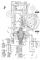
Fig. 1 illustrates an apparatus 10 constructed in
accordance with the present invention. The apparatus
10 helps to turn steerable wheels 12 of a vehicle in
response to rotation of a hand wheel 14 of the vehicle.
The apparatus 10 includes a hydraulic power
assisted steering gear 16. The steering gear 16
illustrated in Fig . 1 is an integral hydraulic power
steering gear. Other hydraulic power assisted
steering gears are contemplated by this invention, for
example, the steering gear may be a rack and pinion
steering gear.
The steering gear 16 includes a housing 18 and a
drive mechanism 20. The drive mechanism 20 is moved in
response to rotation of the hand wheel 14 of the
vehicle. The motion of the drive mechanism 20 results
in a turning of the steerable wheels 12 of the vehicle.
The drive mechanism 20 includes a sector gear 22
having a plurality of teeth 24. The sector gear 22 is
fixed on an output' shaft 26 that extends outwardly
through an opening in the housing 18. The output shaft
26 is typically connected to a pitman arm (not shown)
that is connected to the steering linkage of the
vehicle. The dashed lines between the output shaft 26
and the steerable wheels 12 in,Fig. 1 schematically
represent the pitman arm and steering, linkage. Thus,
as the sector gear 22 rotates, the output shaft 26 is
rotated to operate the steering linkage. As a result,
the steerable wheels 12 of the vehicle are turned.
The steering gear 16 further includes a hydraulic
motor 28 for moving the drive mechanism 20. The
hydraulic motor 28 is located within the housing 18 of
the steering gear 16. The housing 18 of the steering
gear 16 has an inner cylindrical surface 30 defining a
chamber 32. A piston 34 is located within the chamber
32 and divides the chamber into opposite chamber
portions 36 and 38. One chamber portion 38 is located
on a first side of the piston 34 and the other chamber
portion 38 is located on a second opposite side of the
piston. The piston 34 creates a seal between the
respective chamber portions 36 and 38 and is capable of
axial movement within the chamber 32. This axial
movement of the piston 34 results in an increase in
volume of one chamber portion, e.g., 36, and a
corresponding decrease in volume of the other chamber
portion, e.g., 38.
A series of rack teeth 40 is formed on the
periphery of the piston 34. The rack teeth 40 act as
an output for the hydraulic motor 28 and mesh with the
teeth 24 formed on the sector gear 22 of the drive
mechanism 20.
A control valve 44 directs the flow of hydraulic
fluid to the hydraulic motor 28. The control valve 44
is located within the housing 18 of the steering gear
16. An inlet 46 provides fluid communication to the
control valve 44 and an outlet 52 provides fluid
communication away from the control valve.
The control valve' 44 is of a conventional design
and includes a valve core portion 54 and a valve sleeve
portion 56 that are connected together through a
torsion bar 58. The control valve 44 directs fluid to
an appropriate chamber portion 36 or 38 of the
hydraulic motor 28. The flow of hydraulic fluid toward
one of the chamber portions 36 or 38 increases the
pressure within that chamber portion. When the
pressure of one chamber portion, e.g., 36, increases
relative to the pressure of the other chamber portion,
e.g., 38, the piston 34 moves axially and the volume of.
the higher-pressure chamber portion increases. The
volume of the higher-pressure chamber portion, e.g.,
36, increases until the pressure within the chamber
portions 36 and 38 equalizes.
As the volume of one chamber portion, e.g., 36,
increases, the volume of the other chamber portion,
e.g., 38, decreases. The decreasing chamber portion,
e.g., 38, is vented to allow a portion of, the fluid
contained in the decreasing chamber portion to, escape.
The escaping fluid exits the housing 18 of the steering
gear 16 via the outlet 52.
The piston 34 of the hydraulic motor 28 contains a
bore 72, partially shown in Fig. 1, which is open
toward the control valve 44. The valve sleeve portion
56 and a follow-up member 74 collectively form an
integral one-piece unit that is supported for rotation
relative to the piston 34 by a plurality of balls 76.
The outer periphery 78 of the follow-up member 74 is
threaded. The plurality of balls 76 interconnects the
threaded outer periphery 78 of the follow-up member 74
with an internal thread 80 formed in the bore 72 of the
piston 34. As a result of the interconnecting
plurality of balls 76, axial movement of the piston 34
causes the follow-up member 74 and the valve sleeve
portion 56 to rotate. The rotation of the follow-up
member 74 and the valve sleeve portion 56 returns the
control valve 44 to the neutral position.
The valve core portion 54 of the control valve 44
is fixedly connected to an input shaft 82. As shown
schematically by dashed lines in Fig. 1, the input
shaft 82 is fixedly connected to the hand wheel 14 of
the vehicle. Rotation of the hand wheel 14 results in
rotation of the input shaft 82 and rotation of the
valve core 52.
The torsion bar 84 of the steering gear 16 has
first and second ends 84 and 86, respectively. The
first end 84 of the torsion bar 58 is fixed relative to
the input shaft 82 and the valve core portion 54 of the
control valve 44. The second end 86 of the torsion bar
58 is fixed relative to the valve sleeve portion 56 of
the control valve 44 and the follow-up member 74.
When the resistance to turning of the steerable
wheels 12 of the vehicle is below a predetermined
amount, rotation of the hand wheel 14 is transferred
through the torsion bar 58 and causes rotation of the
follow-up member 74. As a result, the control valve 44
remains in the neutral position. Rotation of the
follow-up member 74 causes movement of the piston 34
and results in turning of the steerable wheels 12.
When resistance to turning the steerable wheels 12
of the vehicle is at or above the predetermined amount,
rotation of the follow-up member 74 is resisted. As a
result, rotation of the hand wheel 14 rotates the first
end 84 of the torsion bar 58 relative to the second end
86 of the torsion bar. The rotation of the first end
84 of the torsion bar 58 relative to the second end 86
of the torsion bar results in torsion or twisting
across the torsion bar. As a result of torsion across
the torsion bar 58, the valve core portion 54 of the
control valve 44 rotates relative to the valve sleeve
portion 56 of the control valve and the control valve
44, when supplied with hydraulic fluid, directs fluid
toward one of the chamber portions 36 or 38 of the
hydraulic motor 28.
As discussed above, when fluid is directed toward
one of the chamber portions 36 or 38, the piston 34
moves within the chamber 32. Movement of the piston 34
results in turning of the steerable wheels 12 of the
vehicle, as well as, rotation of the follow-up member
74. As discussed above, rotation of the follow-up
member 74 rotates the valve sleeve portion 56 until the
control valve 44 is again in the neutral position.
When the control valve 44 is in the neutral position,
the torsion across the torsion bar 58 is removed and
the first end 84 of the torsion bar is no longer
rotated or twisted relative to the second end 86 of the
torsion bar.
The apparatus 10 includes a pump 84 that is in
fluid communication with the steering gear 16 for
supplying hydraulic fluid to the steering gear. The
pump 84 draws hydraulic fluid from a fluid reservoir 86
and supplies the hydraulic fluid to the inlet 46 of the
steering gear 16. The pump 84 may be of any
conventional design. An electric pump motor 88 is
operatively connected with the pump 84. The pump motor
88 receives electric power from a power source 90. The
power source 90 may be the vehicle battery. When
energized; the pump motor 88 drives the pump 84 to
supply hydraulic fluid to the steering gear 16.
The apparatus 10 also includes an electric motor
92 for actuating the steering gear 16. The electric
motor 92 may be of any conventional design. The
electric motor 92 receives electric power from the
power source 90. An output shaft (not shown) of the
electric motor 92 is connected to the input shaft 82 of
the steering gear 16. Preferably, a gear assembly 94
is used to connect the output shaft of the electric
motor 92 to the input shaft 82 of the steering gear 16.
When the electric motor 92 receives electric power, the
output shaft of the electric motor 92 rotates the input
shaft 82 of the steering gear 16. Thus, the electric
motor 92 is said to be "in series connection" with the
hydraulic motor 28.
The apparatus 10 also includes a column torque
sensor 96 for sensing column torque and outputting a
signal indicative of the column torque. Column torque
is related to the torsion across the torsion bar 58 and
the material properties of the torsion bar. The column
torque sensor 96 may measure the rotational movement of
the first end 84 of the torsion bar 58 relative to the
second end 86 of the torsion bar. The movement of the
valve core portion 54 relative to the valve sleeve
portion 56 alternatively may be measured for indicating
the relative rotation between the first end 84 and the
second end 86 of the torsion bar 58.
The apparatus 10 also includes a plurality of
vehicle condition sensors 98, 100 and 102 and a
controller 104. Preferably, the vehicle condition
sensors include a lateral acceleration sensor 98, a
hand wheel rotation sensor 100, and a vehicle speed
sensor 102. Each sensor 98, 100 and 102 is
electrically connected to the controller 104.
The lateral acceleration sensor 98 senses the
lateral acceleration of the vehicle and generates an
electrical signal indicative of the sensed lateral
acceleration. The hand wheel.rotation sensor 100
senses the magnitude, rate, and acceleration of
rotation of the vehicle hand wheel 14 and generates
electrical signals indicative of these parameters. The
hand wheel rotation magnitude is the angle of rotation
of the hand wheel 14 relative to a straight ahead
position of the hand wheel. Rotation of the hand wheel
14 in a first direction may be designated as a positive
value and rotation of the hand wheel 14 in a second
direction, opposite the first direction, may be
designated as a negative value. The hand wheel
rotation sensor 100, or the controller 104, may
determine the rate of rotation of the hand wheel 14 by
taking a time differential of the magnitude and may
determine the hand wheel acceleration by taking a time
differential of the rate of rotation. The vehicle
speed sensor 102 senses the vehicle speed and generates
an electrical signal indicative of the speed.
The controller 104 receives the signals generated
by the lateral acceleration sensor 98, the hand wheel
rotation sensor 100, and the vehicle speed sensor 102.
Additionally, the controller 104 receives the column
torque signal from the column torque sensor 96. The
controller 104 analyzes the respective signals using a
known algorithm and generates a control signal for
controlling the electric motor 92. The electric motor
92 is controlled for actuating the steering gear 16 so
as to provide a predetermined resistance to rotation of
the hand, wheel 14.
When the electric motor 92 receives electric
power, the output shaft of the electric motor 92,
through the gear assembly 94, rotates the input shaft
82 of the seering ; gear, 16. As a result, the electric
motor 92 assists the operator in rotating the input
shaft 82 of the steering gear 18.
Additionally, the controller 104 compares the
signal from the vehicle speed sensor 102 to a
predetermined value. When the comparison indicates
that the vehicle speed is below the predetermined
value, the controller 104. actives the pump 84 to supply
hydraulic fluid to the steering gear 16. For example,
when the vehicle speed is below twenty kilometers per
hour, the controller 104 activates the pump 84. To
activate the pump 84 of Fig. 1, the controller 104
controls the pump motor 88 to drive pump 84. When the
controller 104 determines that the vehicle speed is
greater than the predetermined value, the controller
104 deactivates the pump 84 to discontinue supplying
fluid to the steering gear 16. To deactivate the pump
84, the controller 104 shuts down the pump motor 88.
Thus, when the controller 104 determines that the
vehicle speed is greater than the predetermined value,
the controller 104 terminates operation of the
hydraulic motor 28 of the steering gear 16.
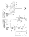
Fig. 2 is a flow chart illustrating the process
200 performed by the controller 104 of Fig. 1. The
process 200 begins at step 202. At step 204, the
controller 104 monitors the handwheel rotation. At
step 206, the controller 104 monitors the vehicle
speed. At step 208, the controller 104 monitors the
lateral acceleration of the vehicle and, the column
torque is monitored at step 210. At step 212, the
controller 104 analyzes the signals received at steps
204, 206, 208, and 210 and output the control signal to
control the electric motor 92. At step 214, a
determination is made as to whether the vehicle speed
is below a predetermined value. If the determination
at step 214 is negative, the process 200 returns to
step 204. If the determination at step 214 is
affirmative, the process 200 proceeds to step 216. At
step 216, the controller 104 activates the pump 84 to
supply fluid to the steering gear 16. From step 216,
the process 200 returns to step 204.
The apparatus 10 of the present invention provides
a power-assisted steering system that includes a
hydraulic boost when the vehicle is operating at low
speeds . Generally, at lower vehicle speeds, the
resistance to rotation of steerable wheels 12 is
increased and the magnitude of a turn of the steerable
wheels 12 is increased; as compared to while operating
a higher vehicle speeds. The apparatus 10 of the
present invention aids the vehicle driver in turning
the steering wheels 12 while operating at the lower
speeds in which additional steering assistance is
generally most helpful.
Fig. 3 illustrates an apparatus 10A constructed in
accordance with a second embodiment of the present
invention. Structures of Fig. 3 that are the same as
or similar to structures of Fig. 1 are numbered using
the same reference numbers and are not discussed in
detail with regard to Fig. 3. Only the differences
between the apparatus 10 of Fig. 1 and the apparatus
10A of Fig. 3 are discussed in detail below.
Unlike the pump 84,of the apparatus 10 illustrated
in Fig. 1, an electric pump motor 88 does not drive the
pump 110 of the apparatus 10A of Fig. 3. The pump 110
of Fig. 3 is operatively connected to the engine 112 of
the vehicle and is driven by the engine 112 of the
vehicle. A clutch mechanism 114 is interposed between
the vehicle engine 112 and the pump 110. The clutch
mechanism 114 is actuatable between an engaged
condition and a disengaged condition. In the engaged
condition, the clutch mechanism 114 mechanically
interconnects or couples the vehicle engine 112 and the
pump 110 for driving the pump to supply hydraulic fluid
to the steering gear 16. In the disengaged condition,
the vehicle engine 112 and the pump 110 are not
mechanically interconnected, i.e., are decoupled from
one another, so that no power is transferred between
the vehicle engine 112 and the pump 110. Thus, when
the clutch mechanism 114 in the disengaged condition,
the pump 110 is deactivated and discontinues supplying
hydraulic fluid to the steering gear 16.
The clutch mechanism 114 is operatively connected
to the controller 104 and the controller actuates the
clutch mechanism 114 between the engaged and disengaged
conditions. When the controller 104 determines that
the vehicle speed is below the predetermined value
(.e.g., 20 kph), the controller 104 actuates the clutch
mechanism 114 into the engaged condition. When the
clutch mechanism 114 is actuated into the engaged
condition the pump 110 is activated to supply
hydraulic fluid to the steering gear 16. When the,
controller 104 determines that the vehicle speed is
greater than the predetermined value, the controller
104 actuates the clutch mechanism 114 into the
disengaged condition. When the clutch mechanism 114 is
in the disengaged condition, the pump 110 is
deactivated and discontinues supplying fluid to the
steering gear 16. Thus, when the controller 104
determines that the vehicle speed is greater than the
predetermined value, the controller 104 terminates
operation of the hydraulic motor 28 of the steering
gear 16.
In a manner similar to the apparatus 10 of Fig. 1,
the apparatus 10A of Fig. 3 provides a hydraulic boost
when the vehicle is operating at low speeds. Thus, the
apparatus 10A of Fig. 3 aids the vehicle driver in
turning the steering wheels 12 while operating at the
lower speeds in which additional steering assistance is
generally most helpful.
Fig. 4 illustrates an apparatus 10B constructed in
accordance with a third embodiment of the present
invention. Structures of Fig. 4 that are the same as
or similar to structures of Fig. 1 are numbered using
the same reference numbers and are not discussed in
detail with regard to Fig. 4. Only the differences
between the apparatus 10 of Fig. 1 and the apparatus
10B of Fig. 4 are discussed in detail below.
The apparatus 10B of Fig. 4 includes a motor
current sensor 118 for sensing the actual current of
the electric motor 92 and for providing a motor current
signal indicative of the sensed current. The motor
current sensor 118 is operatively connected to the
controller 104. The controller 104 receives the motor
current signal from the motor current sensor 118 and
uses the motor current signal to determine the output
torque of the electric motor 92.
Additionally, the apparatus 10B of Fig. 4 includes
first and second fluid supply systems 120 and 122,
respectively, each for supplying hydraulic fluid to the
steering gear 16. The first fluid supply system 120
includes a first pump 124 and a first reservoir 126.
The first pump 124 draws hydraulic fluid from the first
reservoir 126. A first electric pump motor 128 is
operatively connected with the first pump 124. When
energized, the first pump motor 128 drives the first
pump 124 to supply hydraulic fluid to the steering gear
16. Hydraulic fluid returned from the steering gear 16
to the first fluid supply system 120 is directed into
the first reservoir 126.
The second fluid supply system 122 includes a
second pump 130 and a second reservoir 132. The second
pump 130 draws hydraulic fluid from the second
reservoir 132. A second electric pump motor 134 is
operatively connected with the second pump 130. When
energized, the second pump motor 134 drives the second
pump 130 to supply hydraulic fluid to the steering gear
16. Hydraulic fluid returned from the steering gear 16
to the second fluid supply system 122 is directed into
the second reservoir 132.
The apparatus 10B of Fig. 4 also includes a two-position
valve assembly 138. The two-position valve
assembly 138 is interposed between the first and second
pumps 124 and 130 and the inlet 46 and the steering
gear 16. The two-position valve assembly also is
interposed between the outlet 52 of the steering gear
16 and the first and second reservoirs 126 and 132.
In a first position, illustrated in Fig. 4, the
two-position valve assembly 138 places the first fluid
supply system 120 in fluid communication with the
steering gear 16. Thus, when in the first position,
the two-position valve places the first pump 124 and
the first reservoir 126 in fluid communication with the
steering gear 16. Also, when the two-position valve
assembly 138 is in the first position, the second fluid
supply system 122 is isolated from fluid communication
with the steering gear 16.
In a second position, the two-position valve
assembly 138 places the second fluid supply system 122
in fluid communication with the steering gear 16.
Thus, when in the second position, the two-position
valve assembly 138 places the second pump 130 and the
second reservoir 132 in fluid communication with the
steering gear 16. Also, when the two-position valve
assembly 138 is in the second position, the first fluid
supply system 120 is isolated from fluid communication
with the steering gear 16.
A valve drive 140 is connected with the two-position
valve assembly 138 for positioning of the two-position
valve assembly. Preferably, the valve drive
140 is a solenoid. The valve drive 140 is operatively
connected to the controller 104. The controller 104
controls the valve drive 140. Thus, the controller 104
controls the position of the two-position valve
assembly 138 between the first and second positions for
selectively placing either the first or second fluid
supply system 120 or 122 in fluid communication with
the steering gear 16.
Fig. 5 is a flow chart illustrating the process
500 performed by the controller 104 of Fig. 5. The
process 500 begins at step 502. At step 504, the
controller 104 monitors the hand wheel 14 rotation. At
step 506, the controller 104 monitors the vehicle
speed. At step 508, the controller 104 monitors the
lateral acceleration of the vehicle and, the column
torque is monitored at step 510. At step 512, the
controller 104 analyzes the signals received at steps
504, 506, 508, and 510 and outputs the control signal
to control the electric motor 92. The electric motor
92 is controlled to provide a predetermined resistance
to rotation of the hand wheel 14. At step 514, a
determination is made as to whether the vehicle speed
is below a first predetermined value X. If the
determination at step 514 is, negative, the process 500
returns to step 504. If the determination at step 514
is affirmative, the process 500 proceeds to step 516.
At step 516, the controller 104 activates the
first pump 124 to supply fluid to the control valve 44
of the steering gear 16. From step 516, the process
500 proceeds to step 518. At step 518, the controller
104 actuates the two-position value assembly 32 into
the first position so that the first pump 124 and the
first reservoir 126 are in fluid communication with the
steering gear 16, as shown in Fig. 4.
At step 520, the controller 104 monitors the motor
torque of the electric motor 92. The process 500 then
proceeds to step 522 in which a determination is made
as to whether the motor torque from step 520 is greater
then a second predetermined value Y. If the
determination at step 522 is negative, the controller
104 assumes that the apparatus 10B is properly
operating and the process 500 returns to step 504. If
the determination at step 522 is affirmative and the
motor torque is above the second predetermined value Y,
the controller 104 assumes that the hydraulic motor 28
of the steering gear 16 is not responding properly to
actuation of the steering gear 16 by the electric motor
92. From step 522, the process 500 proceeds to step
524. At step 524, the controller 104 activates the
second pump 130 to supply fluid to the control valve 44
of the steering gear 16. Also, at step 524, the
controller 104 shuts down the first pump 124. From
step 524, the process 500 proceeds to step 526. At
step 526, the controller actuates the two-position
valve assembly 138 into the second position so that the
second pump 130 and the second reservoir 132 are in
fluid communication with the steering gear 16. Thus,
in response to motor torque above the second
predetermined value Y, the controller 104 places the
second fluid supply source 122 in fluid communication
with the steering gear 16 and isolates the first fluid
supply source 120 from fluid communication with the
steering gear 16.
As illustrated in the process 500 of Fig. 5, the
apparatus 10B of Fig. 4 includes redundant first and
second fluid supply systems 120 and 122, each including
a pump 124 and 130, respectively, and a reservoir 126
and 132, respectively. The controller 104 of the
apparatus 10B generally activates the first pump and
places the first fluid supply system 120 in fluid
communication with the steering gear 16 when the
vehicle speed is below, a first predetermined value X.
If the first pump 124 is activated and the first fluid
supply system 120 is in fluid communication with the
steering gear 16 and a determination is made that the
motor torque is greater than the second predetermined
value Y, the controller 104 of the apparatus 10B shuts
down the first pump 124, activates the second pump 130,
and places the second fluid supply system 122 in fluid
communication with the steering gear 16. Thus, the
apparatus 10B of the present invention provides
redundant systems 120 and 122 for supplying hydraulic
fluid to the control valve 44 of the steering gear 16.
Fig. 6 illustrates an apparatus 10C constructed in
accordance with a fourth embodiment of the present
invention. Structures of Fig. 6 that are the same as
or similar to structures of Fig. 4 are numbered using
the same reference numbers and are not discussed in
detail with regard to Fig. 6. Only the differences
between the apparatus 10B of Fig. 4 and the apparatus
10C of Fig. 6 are discussed in detail below. Fig. 6
only illustrates a portion of the steering gear 16,
including the fluid inlet 46 and outlet 52 of the
steering gear 16. It is to be understood that the
steering gear 16 of the apparatus 10C of Fig. 6 is
identical to the steering gear 16 of Fig. 4.
The apparatus 10C of Fig. 6 also includes first
and second fluid supply systems 120 and 122,
respectively, each of which is shown schematically in
Fig. 6. The apparatus 10C of Fig. 6 also includes two
separate and distinct two-position valve assemblies, a
supply valve 146 and a return valve 148.
The supply valve 146 includes parallel inlets 150
and parallel outlets 152. The first and second pumps
124 and 130, respectively, are connected to the inlets
150 of the supply valve 146, each pump to a respective
inlet. One of the outlets 152 of the supply valve 146
is connected to the inlet 46 of the steering gear 16
and the other outlet 152 is connected to an inlet 156
of the return valve 148.
The supply valve 146 has first and second
positions. In a first position, shown in Fig. 6, the
supply valve 146 places the first pump 124 in fluid
communication with the inlet 46 of the steering gear 16
and places the second pump 130 in fluid communication
with the return valve 148. In the second position, the
supply valve 146 places the second pump 130 in fluid
communication with the inlet 46 of the steering gear 16
and places the first pump 124 in fluid communication
with the return valve 148.
A valve drive 154 is connected to the supply valve
146 for actuating the supply valve between the first
and second positions. The valve drive 154 is
preferably a solenoid. The valve drive 154 is
operatively connected to the controller 104 and the
controller controls actuation of the valve drive 154.
The return valve 148 also includes parallel inlets
156 and parallel outlets 158. An outlet 152 of the
supply valve 146 is connected to one of the inlets 156
of the return valve 148 and the outlet 52 of the
steering gear 16 is connected to the other inlet 156 of
the return valve 148. One of the outlets 158 of the
return valve 148 is connected to the first reservoir
126 and the other outlet 158 is connected to the second
reservoir 132.
The return valve 148 has first and second
positions. In a first position, shown in Fig. 6, the
return valve 148 connects the outlet 52 of the steering
gear 16 to the first reservoir 126 and connects the
outlet 152 of the supply valve 146 to the second
reservoir 132. In the second position, the return
valve 148 connects the outlet 52 of the steering gear
16 to the second reservoir 132 and connects the outlet
152 of the supply valve 146 to the first reservoir 126.
A valve drive 160 is connected to the return valve
148 for actuating the return valve 148 between the
first and second positions. The valve drive 160 is
preferably a solenoid. The valve drive 160 is
operatively connected to the controller 104 and the
controller controls actuation of the valve drive.
The apparatus 10C of Fig. 6 is controlled in a
manner similar to the apparatus 10B of Fig. 4. When
the controller 104 determines that the vehicle speed is
below the first predetermined value X, the controller
104 activates the first pump 124 and places the first
fluid supply source 120 in fluid communication with the
steering gear 16. If the controller 104 determines
that the motor torque of electric motor 92 is above the
second predetermined value Y while the first pump 124
is activated and in fluid communication with the
steering gear 16, the controller 104 shuts down the
first pump 124, activates the second pump 130, and
actuates the supply and return valves 146 and 148 to
place the second fluid supply source 122 in fluid
communication with the steering gear 16.
Fig. 7 illustrates an apparatus 10D constructed in
accordance with a fifth embodiment of the present
invention. Structures of Fig. 7 that are the same as
or similar to structures of Fig. 6 are numbered using
the same reference numbers and are not discussed in
detail with regard to Fig. 7. Only the differences
between the apparatus 10C of Fig. 6 and the apparatus
10D of Fig. 7 are discussed in detail below. Similar
to Fig. 6, Fig. 7 only illustrates a portion of the
steering gear 16, including the fluid inlet 46 and
outlet 52 of the steering gear 16.
The apparatus 10D of Fig. 7 also includes first
and second fluid supply systems 120 and 122,
respectively, each of which is shown schematically in
Fig. 7. The apparatus 10D of Fig. 7 also includes
three separate and distinct two-position valve
assemblies, first and second supply valves 170 and 712,
respectively, and a return valve 174.
The first supply valve 170 controls fluid flow
from the first fluid supply system 120 and includes a
single inlet 176 and two outlets 178. The first pump
124 is connected to the inlet 176 of the first supply
valve 170. One of the outlets 178 of the first supply
valve 170 is connected to the inlet 46 of the steering
gear 16, through a check valve 180, and the other
outlet 178 of the first supply valve 170 is connected
to the first reservoir 126.
The first supply valve 170 has first and second
positions. In a first position, shown in Fig. 7, the
first supply valve 170 places the first pump 124 in
fluid communication with the inlet 46 of the steering
gear 16. In the second position, the first supply
valve 170 places the first pump 124 in fluid
communication with the first reservoir 126.
A valve drive 182 is connected to the first supply
valve 170 for actuating the first supply valve 170
between the first and second positions. The valve
driver 182 is preferably a solenoid. The valve drive
182 is operatively connected to the controller 104 and
the controller controls actuation of the valve drive
182.
The second supply valve 172 controls fluid flow
from the second fluid supply system 122 and includes a
single inlet 184 and two outlets 186. The second pump
130 is connected to the inlet 184 of the second supply
valve 172. One of the outlets 186 of the second supply
valve 172 is connected to the inlet 46 of the steering
gear 16, through a check valve 188, and the other
outlet 186 of the second supply valve 172 is connected
to the second reservoir 132.
The second supply valve 172 has first and second
positions. In a first position, shown in Fig. 7, the
second supply valve 172 places the second pump 130 in
fluid communication with the second reservoir 132. In
the second position, the second supply valve 172 places
the second pump 130 in fluid communication with the
inlet 46 of the steering gear 16.
A valve drive 190 is connected to the second
supply valve 172 for actuating the second supply valve
between the first and second positions. The valve
drive 190 is preferably a solenoid. The valve drive
190 is operatively connected to the controller 104 and
the controller controls actuation of the valve drive
190.
The return valve 194 also includes a single inlet
192 and two outlets 194. The outlet 52 of the steering
gear 16 is connected to the inlet 192 of the return
valve 174. One of the outlets 194 of the return valve
174 is connected to the first reservoir 126 and the
other outlet 194 is connected to the second reservoir
132.
The return valve 174 has first and second
positions. In a first position, shown in Fig. 7, the
return valve 174 places the outlet 52 of the steering
gear 16 in fluid communication with the first reservoir
126. In the second position, the return valve 174
places the outlet 52 of the steering gear 16 in fluid
communication with the second reservoir 132.
A valve drive 196 is connected to the return valve
174 for actuating the return valve, between the first
and second positions. The valve drive 196 is
preferably a solenoid. The valve drive 196 is
operatively connected to the controller 104 and the
controller controls actuation of the valve drive.
The apparatus 10D of Fig. 7 is controlled in a
manner similar to the apparatuses 10B and 10C of Figs.
4 and 6, respectively. When the controller 104
determines that the vehicle speed is below the first
predetermined value X, the controller 104 activates the
first pump 124 and places the first fluid system 120 in
fluid communication with the steering gear 16, i.e.,
places the first pump 124 in fluid communication with
the inlet 46 of the steering gear 16 and places the
outlet 52 of the steering gear 16 in fluid
communication with the first reservoir 126. If the
controller 104 determines that the motor torque of
electric motor 92 is above the second predetermined
value while the first pump 124 is activated and the
first fluid system 120 is in fluid communication with
the steering gear 16, the controller 104 shuts down the
first pump 124, activates the second pump 130, and
places the second fluid supply system 122 in fluid
communication with the steering gear 16, i.e., places
the second pump 130 in fluid communication with the
inlet 46 of the steering gear 16 and places the outlet
52 of the steering gear 16 in fluid communication with
the second reservoir 132.
Similar to the apparatuses 10 and 10A of Figs. 1
and 3,' the apparatuses 10B, 10C, and 10D of Figs. 4, 6,
and 7 provide a power assisted steering system that
includes a hydraulic boost when the vehicle is
operating at low speeds. The apparatuses 10B, 10C, and
10D of Figs. 4, 6, and 7 also include redundant fluid
supply systems 120 and 122 for supplying hydraulic
fluid to a hydraulic motor 28 of a steering gear 16 for
providing the hydraulic boost.
From the above description of the invention, those
skilled in the art will perceive improvements, changes
and modifications. Such improvements, changes and
modifications within the skill of the art are intended
to be covered by the appended claims.