EP1582384A1 - Air treatment system housing - Google Patents
Air treatment system housing Download PDFInfo
- Publication number
- EP1582384A1 EP1582384A1 EP05005323A EP05005323A EP1582384A1 EP 1582384 A1 EP1582384 A1 EP 1582384A1 EP 05005323 A EP05005323 A EP 05005323A EP 05005323 A EP05005323 A EP 05005323A EP 1582384 A1 EP1582384 A1 EP 1582384A1
- Authority
- EP
- European Patent Office
- Prior art keywords
- treatment system
- air treatment
- housing structure
- issue
- system housing
- Prior art date
- Legal status (The legal status is an assumption and is not a legal conclusion. Google has not performed a legal analysis and makes no representation as to the accuracy of the status listed.)
- Granted
Links
Images
Classifications
-
- B—PERFORMING OPERATIONS; TRANSPORTING
- B60—VEHICLES IN GENERAL
- B60H—ARRANGEMENTS OF HEATING, COOLING, VENTILATING OR OTHER AIR-TREATING DEVICES SPECIALLY ADAPTED FOR PASSENGER OR GOODS SPACES OF VEHICLES
- B60H1/00—Heating, cooling or ventilating devices
- B60H1/00507—Details, e.g. mounting arrangements, desaeration devices
- B60H1/00514—Details of air conditioning housings
-
- B—PERFORMING OPERATIONS; TRANSPORTING
- B60—VEHICLES IN GENERAL
- B60H—ARRANGEMENTS OF HEATING, COOLING, VENTILATING OR OTHER AIR-TREATING DEVICES SPECIALLY ADAPTED FOR PASSENGER OR GOODS SPACES OF VEHICLES
- B60H1/00—Heating, cooling or ventilating devices
- B60H1/00007—Combined heating, ventilating, or cooling devices
- B60H1/00021—Air flow details of HVAC devices
- B60H1/00028—Constructional lay-out of the devices in the vehicle
Definitions
- the present invention relates, in general terms, to air treatment system housing structures, such as, for example, a housing structure for a motor vehicle heating ventilation and/or air conditioning system.
- An air treatment system housing and, in particular, a housing for a vehicle air conditioning system are conventionally constructed from a multiplicity of separate housing parts which are then mounted separately in the vehicle and, during mounting, are brought reciprocally into engagement with one another in an airtight manner.
- a fan housing is provided, to which an air filter housing is attached, after which, conventionally, the actual air conditioning housing is provided, in which appropriate receptacles are formed for heat exchangers, such as, for example, the heating body and the evaporator of an air conditioning system refrigerating circuit.
- This last-mentioned housing also conventionally has arranged in it the corresponding actuation elements, such as air and mixing flaps.
- the object of the present invention is, therefore, to provide an air treatment system housing structure which can counteract the abovementioned disadvantages.
- the air treatment system housing structure should be capable of being produced simply and cost-effectively and have sufficient structural intactness and make it possible to have a reduced number of parts and a reduced outlay in mounting terms.
- the present invention accordingly proposes an air treatment system housing structure comprising at least two sections which are connected to one another in one piece and serve in each case for the reception of components belonging to different functional groups of the air treatment system and between which an air path is formed, at least two adjacent sections having, in addition to an issue or opening common to them, in each case at least one further issue or opening, the issue normal vectors of which are different. It was found, extremely surprisingly, that it is possible to provide an air treatment system housing structure with a reduced number of parts which may comprise different sections for the purpose of the reception of different components of the air treatment system, such as, for example, a section for receiving the blower, a section for receiving an air filter device and a section for receiving the thermodynamic components of a heating air conditioning system.
- issue normal vectors of at least two adjacent sections it is likewise possible, in specific applications, to provide appropriately oriented issue regions for individual adjacent sections, so that it is preferable, in an air treatment system housing structure according to the invention, for issue normal vectors of at least two adjacent sections to be essentially parallel to one another.
- the issue normal vectors of at least two adjacent sections are essentially oppositely parallel.
- Such a configuration can be produced particularly simply, for example, by the injection molding method by means of an individual two-part injection molding die, the molding parts of which are displaceable according to the issue normal vectors.
- the issue normal vectors of at least two adjacent sections can run essentially perpendicularly to one another.
- the structural intactness of the air treatment system housing structure formed is high, and, depending on the vehicle geometry, this can also make it possible in a simple way to have corresponding access, required for maintenance purposes, after mounting.
- the further issues it is possible, for example, for the further issues to extend, for example, essentially helically around the entire housing structure if, for example, there is provision for the section serving for receiving the blower to issue upward and for the section serving for receiving the air filter to issue forward, while a section serving for the reception of thermodynamic elements of the air conditioning system issues downward.
- the perpendicular orientation has the advantage that a shaping die can be designed in a correspondingly simple way.
- all the sections of the air treatment system housing structure have at least one common wall, as a result of which, for example, highly accurate mounting interfaces with regard to the body and/or high structural intactness can be provided.
- At least two adjacent sections comprise two common walls running essentially parallel.
- parallel walls is in this case to be understood in a broad interpretation, since it is possible, for example, to understand the said meaning that, essentially in the orientation mounted in the vehicle, the front wall of the housing structure is common to all the sections, and it is also possible for the rear wall of the structure, while the respective corresponding further issues are oriented upward or downward.
- the term "essentially perpendicular" is to be interpreted broadly and is to be understood as meaning that two adjacent sections have a common angled wall structure, so that they have, for example, a common bottom wall and a common rear wall, while, for example, one section has a wider issue in the front region, while the other section has its wider issue oriented upward.
- the sections making up the structure in each case form a fan receptacle, an air filter receptacle and a heat exchanger receptacle, in particular arranged in this order.
- the air treatment system housing structure according to the invention may be provided in such a way that the section forming the fan receptacle and the section forming the air filter receptacle have parallel issue normal vectors, while the section forming the heat exchanger receptacle has an in this respect oppositely parallel issue normal vector, in each case with respect to the further issues.
- a housing structure of this type corresponds essentially to two reception spaces which are located next to one another and are rotated through 180°.
- the air treatment system housing structure is designed in such a way that the further issues are forming die removal orifices, in which case it is particularly advantageous if the contiguous walls allow simple removal from the mold, in that the contiguous walls do not have any offsets which are not parallel to the respective issue normal vectors of the further issues.
- the present invention thus makes it possible, in a complete departure from the practice customary hitherto, according to which individual modules are used for the housing structure, to provide a fundamental basic structure, so that tolerances existing between the separate modules can be eliminated. Owing to the misorientation of the issue normal vectors of the further issues of the individual sections, a sufficient structural intactness can be obtained in an extremely surprising and simple way, without the production method becoming excessively complex as a result, thus allowing a quite surprising saving of parts and assembly costs and also an increase in safety against leakage.
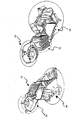
- the illustrated housing structure of the preferred embodiment is formed essentially from a section 20 which serves for receiving a blower or fan, from a section 30 which is provided for receiving an air filter, in the present case an air filter to be arranged in a V-shaped manner, and a section 40 in which the various thermodynamic components, such as the air stream control and regulating elements, can be received.
- the entire housing structure is produced, as illustrated, in one piece, for example, by means of an injection molding method, and has a multiplicity of body-side fastening means which, owing to the provision of the housing structure in one piece, can have high accuracy, that is to say low tolerances.
- the sections 20 and 30 have in each case a common issue, by means of which they are reciprocally connected and define an air path, and a further issue region which is oriented downward in the illustration of the left side and is oriented upward in the illustration on the right side.
- the two issue regions lie on different planes, but the issue region normal vectors run parallel and codirectionally to one another.
- the section 40 which is connected to the section 30 adjacently to the latter via a common issue region, has a further issue region which is oriented upward in the illustration in the left portion of the single figure and is oriented downward in the illustration on the right side of the figure.
- the issue normal vector runs parallel to those of the sections 20 and 30, but in the opposite direction. It should be noted that, in the illustration on the left side of the figure, the front wall is partially cut away, although this does not constitute the further issue region.
- the present invention was described above with full reference to a currently preferred embodiment, a person skilled in the art should recognize that the most diverse possible variations and modifications are possible within the scope of the claims.
- a person skilled in the art should recognize that the one-piece housing structure could also be configured in another way, where appropriate at the expense of a somewhat more complex production method.
- a considerable factor, ultimately, is that the housing structure is one-piece overall, structural intactness being achieved effectively and simply due to the misorientation of the issue normal vectors of the further issues.
Landscapes
- Physics & Mathematics (AREA)
- Thermal Sciences (AREA)
- Engineering & Computer Science (AREA)
- Mechanical Engineering (AREA)
- Air-Conditioning For Vehicles (AREA)
- Air Filters, Heat-Exchange Apparatuses, And Housings Of Air-Conditioning Units (AREA)
- Cultivation Receptacles Or Flower-Pots, Or Pots For Seedlings (AREA)
Abstract
Description
- The present invention relates, in general terms, to air treatment system housing structures, such as, for example, a housing structure for a motor vehicle heating ventilation and/or air conditioning system.
- An air treatment system housing and, in particular, a housing for a vehicle air conditioning system are conventionally constructed from a multiplicity of separate housing parts which are then mounted separately in the vehicle and, during mounting, are brought reciprocally into engagement with one another in an airtight manner. Conventionally, for this purpose, a fan housing is provided, to which an air filter housing is attached, after which, conventionally, the actual air conditioning housing is provided, in which appropriate receptacles are formed for heat exchangers, such as, for example, the heating body and the evaporator of an air conditioning system refrigerating circuit. This last-mentioned housing also conventionally has arranged in it the corresponding actuation elements, such as air and mixing flaps. Depending on the application, these individual modules or units are preassembled in order to be introduced into the vehicle or, alternatively, are only combined during mounting in the vehicle. However, this modular provision has various disadvantages, particularly with regard to the large number of plastic parts, the large number of interfaces which may lead to corresponding leakages, and resulting high tolerances in terms of final mounting. Furthermore, a corresponding modular concept has the disadvantage that correspondingly high mounting costs are incurred.
- The object of the present invention is, therefore, to provide an air treatment system housing structure which can counteract the abovementioned disadvantages. The air treatment system housing structure should be capable of being produced simply and cost-effectively and have sufficient structural intactness and make it possible to have a reduced number of parts and a reduced outlay in mounting terms.
- The abovementioned object is achieved, according to the invention, by means of an air treatment system housing structure having the features of claim 1, preferred embodiments being the subject matter of the dependent claims.
- In particular, the present invention accordingly proposes an air treatment system housing structure comprising at least two sections which are connected to one another in one piece and serve in each case for the reception of components belonging to different functional groups of the air treatment system and between which an air path is formed, at least two adjacent sections having, in addition to an issue or opening common to them, in each case at least one further issue or opening, the issue normal vectors of which are different. It was found, extremely surprisingly, that it is possible to provide an air treatment system housing structure with a reduced number of parts which may comprise different sections for the purpose of the reception of different components of the air treatment system, such as, for example, a section for receiving the blower, a section for receiving an air filter device and a section for receiving the thermodynamic components of a heating air conditioning system.
- Since the individual sections are produced in one piece, leakages can be effectively prevented, and the entire part can be cost-effectively produced and also mounted, with lower tolerances being adhered to. Moreover, due to the provision of further issue regions lying in different planes, high structural intactness can be achieved, so that the structure thus constructed from different sections has sufficient distortion resistance. Furthermore, owing to the different issue normal vectors, a corresponding maintenance requirement of the components to be received can be taken into account.
- It should be noted that, although it is also possible to provide a misorientation of the issue normal vectors in each case between adjacent sections, it is likewise possible, in specific applications, to provide appropriately oriented issue regions for individual adjacent sections, so that it is preferable, in an air treatment system housing structure according to the invention, for issue normal vectors of at least two adjacent sections to be essentially parallel to one another.
- In a particularly preferred embodiment, the issue normal vectors of at least two adjacent sections are essentially oppositely parallel. Such a configuration can be produced particularly simply, for example, by the injection molding method by means of an individual two-part injection molding die, the molding parts of which are displaceable according to the issue normal vectors.
- Alternatively or additionally, it is possible for the issue normal vectors of at least two adjacent sections to run essentially perpendicularly to one another. In such a configuration, in particular, the structural intactness of the air treatment system housing structure formed is high, and, depending on the vehicle geometry, this can also make it possible in a simple way to have corresponding access, required for maintenance purposes, after mounting. By means of such a configuration, it is possible, for example, for the further issues to extend, for example, essentially helically around the entire housing structure if, for example, there is provision for the section serving for receiving the blower to issue upward and for the section serving for receiving the air filter to issue forward, while a section serving for the reception of thermodynamic elements of the air conditioning system issues downward. Although a misorientation of the issue normal vectors which is not at right angles is also possible, the perpendicular orientation has the advantage that a shaping die can be designed in a correspondingly simple way.
- Advantageously, all the sections of the air treatment system housing structure have at least one common wall, as a result of which, for example, highly accurate mounting interfaces with regard to the body and/or high structural intactness can be provided.
- According to a preferred embodiment, at least two adjacent sections comprise two common walls running essentially parallel. The term "parallel walls" is in this case to be understood in a broad interpretation, since it is possible, for example, to understand the said meaning that, essentially in the orientation mounted in the vehicle, the front wall of the housing structure is common to all the sections, and it is also possible for the rear wall of the structure, while the respective corresponding further issues are oriented upward or downward.
- Furthermore, it is advantageous if at least two adjacent sections have two essentially perpendicular common walls. In this case, too, the term "essentially perpendicular" is to be interpreted broadly and is to be understood as meaning that two adjacent sections have a common angled wall structure, so that they have, for example, a common bottom wall and a common rear wall, while, for example, one section has a wider issue in the front region, while the other section has its wider issue oriented upward.
- In a particularly preferred embodiment, the sections making up the structure in each case form a fan receptacle, an air filter receptacle and a heat exchanger receptacle, in particular arranged in this order.
- The air treatment system housing structure according to the invention may be provided in such a way that the section forming the fan receptacle and the section forming the air filter receptacle have parallel issue normal vectors, while the section forming the heat exchanger receptacle has an in this respect oppositely parallel issue normal vector, in each case with respect to the further issues. In other words, a housing structure of this type corresponds essentially to two reception spaces which are located next to one another and are rotated through 180°.
- Finally, it is preferable that, for the purpose of simple production by means of forming dies, such as, for example, injection molding dies, the air treatment system housing structure is designed in such a way that the further issues are forming die removal orifices, in which case it is particularly advantageous if the contiguous walls allow simple removal from the mold, in that the contiguous walls do not have any offsets which are not parallel to the respective issue normal vectors of the further issues.
- In summary, the present invention thus makes it possible, in a complete departure from the practice customary hitherto, according to which individual modules are used for the housing structure, to provide a fundamental basic structure, so that tolerances existing between the separate modules can be eliminated. Owing to the misorientation of the issue normal vectors of the further issues of the individual sections, a sufficient structural intactness can be obtained in an extremely surprising and simple way, without the production method becoming excessively complex as a result, thus allowing a quite surprising saving of parts and assembly costs and also an increase in safety against leakage.
- Moreover, further advantages and features of the present invention may be gathered from the following description, given merely by way of example, of a currently preferred embodiment, this description not being restrictive and referring to the accompanying drawing which illustrates a motor vehicle air conditioning system housing structure in perspective in two different views as a preferred embodiment of the present invention.
- The illustrated housing structure of the preferred embodiment is formed essentially from a
section 20 which serves for receiving a blower or fan, from asection 30 which is provided for receiving an air filter, in the present case an air filter to be arranged in a V-shaped manner, and asection 40 in which the various thermodynamic components, such as the air stream control and regulating elements, can be received. The entire housing structure is produced, as illustrated, in one piece, for example, by means of an injection molding method, and has a multiplicity of body-side fastening means which, owing to the provision of the housing structure in one piece, can have high accuracy, that is to say low tolerances. - As may gathered from the perspective illustrations, the
sections - In contrast to this, the
section 40, which is connected to thesection 30 adjacently to the latter via a common issue region, has a further issue region which is oriented upward in the illustration in the left portion of the single figure and is oriented downward in the illustration on the right side of the figure. In other words, the issue normal vector runs parallel to those of thesections - The embodiment illustrated, with the respective issue regions in essentially parallel planes and with at least partially oppositely directed normal vectors, makes it possible, as becomes clear to a person skilled in the art from the drawing, to have effective and simple production by means of a very simple injection molding die, since it is sufficient to provide only a two-part mold, since all the housing wall sections are illustrated as being free of any offset.
- Although the present invention was described above with full reference to a currently preferred embodiment, a person skilled in the art should recognize that the most diverse possible variations and modifications are possible within the scope of the claims. In particular, a person skilled in the art should recognize that the one-piece housing structure could also be configured in another way, where appropriate at the expense of a somewhat more complex production method. A considerable factor, ultimately, is that the housing structure is one-piece overall, structural intactness being achieved effectively and simply due to the misorientation of the issue normal vectors of the further issues.
Claims (10)
- An air treatment system housing structure, comprising at least two sections (20, 30, 40) which are connected to one another in one piece and serve in each case for the reception of components belonging to different functional groups of the air treatment system and between which an air path is formed, at least two adjacent sections (20, 30; 30, 40) having, in addition to an issue common to them, in each case at least one further issue, the issue normal vectors of which are different.
- The air treatment system housing structure as claimed in claim 1, wherein the issue normal vectors of at least two adjacent sections (20, 30; 30, 40) are essentially parallel.
- The air treatment system housing structure as claimed in claim 1 or 2, wherein the issue normal vectors of at least two adjacent sections are essentially oppositely parallel.
- The air treatment system housing structure as claimed in one of claims 1 - 3, wherein the issue normal vectors of at least two adjacent sections run essentially perpendicularly to one another.
- The air treatment system housing structure as claimed in one of the preceding claims, wherein all the sections (20, 30, 40) have at least one common wall.
- The air treatment system housing structure as claimed in one of the preceding claims, wherein at least two adjacent sections (20, 30; 30, 40) have two common walls running essentially parallel.
- The air treatment system housing structure as claimed in one of the preceding claims, wherein at least two adjacent sections (20, 30; 30, 40) have two essentially perpendicular common walls.
- The air treatment system housing structure as claimed in one of the preceding claims, wherein the sections (20, 30, 40) form in each case a fan receptacle, an air filter receptacle and a heat exchanger receptacle, in particular arranged in this order.
- The air treatment system housing structure as claimed in claim 8, wherein the section (20) forming the fan receptacle and the section (30) forming the air filter receptacle have parallel issue normal vectors, while the section (40) forming the heat exchanger receptacle has an in this respect oppositely parallel issue normal vector, in each case with respect to the further issues.
- The air treatment system housing structure as claimed in one of the preceding claims, wherein the further issues are forming die removal orifices, in particular contiguously to walls which have no offsets non-parallel to the respective issue normal vectors of the further issues.
Applications Claiming Priority (2)
| Application Number | Priority Date | Filing Date | Title |
|---|---|---|---|
| DE102004015270 | 2004-03-29 | ||
| DE102004015270A DE102004015270A1 (en) | 2004-03-29 | 2004-03-29 | Air treatment system housing structure |
Publications (2)
| Publication Number | Publication Date |
|---|---|
| EP1582384A1 true EP1582384A1 (en) | 2005-10-05 |
| EP1582384B1 EP1582384B1 (en) | 2008-02-27 |
Family
ID=34877637
Family Applications (1)
| Application Number | Title | Priority Date | Filing Date |
|---|---|---|---|
| EP05005323A Expired - Lifetime EP1582384B1 (en) | 2004-03-29 | 2005-03-11 | Air treatment system housing |
Country Status (5)
| Country | Link |
|---|---|
| US (1) | US20050210845A1 (en) |
| EP (1) | EP1582384B1 (en) |
| AT (1) | ATE387330T1 (en) |
| DE (2) | DE102004015270A1 (en) |
| ES (1) | ES2302086T3 (en) |
Citations (2)
| Publication number | Priority date | Publication date | Assignee | Title |
|---|---|---|---|---|
| US5954578A (en) * | 1996-08-05 | 1999-09-21 | Denso Corporation | Air conditioner for a vehicle |
| DE10042683A1 (en) * | 2000-08-31 | 2002-03-14 | Behr Gmbh & Co | Air conditioning unit for motor vehicles has two housing sections ate 90o to each other, and connected via flow channel connector |
Family Cites Families (17)
| Publication number | Priority date | Publication date | Assignee | Title |
|---|---|---|---|---|
| US2253671A (en) * | 1939-08-28 | 1941-08-26 | Gen Motors Corp | Vehicle heating and windshield defrosting device |
| US2729158A (en) * | 1949-05-07 | 1956-01-03 | Daimler Benz Ag | Heating installation for motor vehicles |
| US2800068A (en) * | 1952-11-06 | 1957-07-23 | Gen Motors Corp | Heating, ventilating, and windshield defrosting apparatus |
| US2832277A (en) * | 1953-07-29 | 1958-04-29 | Eaton Mfg Co | Vehicle heating and ventilating apparatus |
| GB1073077A (en) * | 1965-10-14 | 1967-06-21 | Ford Motor Co | Motor vehicle heating and ventilating system |
| JP2566044B2 (en) * | 1990-05-25 | 1996-12-25 | 日産自動車株式会社 | Heater unit structure of vehicle air conditioner |
| FR2706816A1 (en) * | 1993-06-23 | 1994-12-30 | Valeo Thermique Habitacle | Apparatus for heating-ventilating and/or air-conditioning the passenger compartment of a motor vehicle, especially an electric vehicle |
| US5399120A (en) * | 1993-11-05 | 1995-03-21 | General Motors Corporation | Air conditioning system control valve |
| GB9423776D0 (en) * | 1994-11-25 | 1995-01-11 | Acg Deutschland Gmbh | Dashboard assembly |
| KR100316163B1 (en) * | 1996-07-27 | 2002-12-05 | 한라공조주식회사 | Air conditioning apparatus |
| JPH10217745A (en) * | 1997-01-31 | 1998-08-18 | Zexel Corp | Air conditioner case |
| US5980380A (en) * | 1997-10-27 | 1999-11-09 | Valeo Climate Control, Inc. | Ventilation unit |
| FR2773113B1 (en) * | 1997-12-26 | 2000-08-04 | Valeo Climatisation | HEATING AND AIR CONDITIONING DEVICE INTEGRATED INTO A DASHBOARD OF A MOTOR VEHICLE |
| FR2799414B1 (en) * | 1999-10-08 | 2001-12-14 | Valeo Climatisation | IMPROVED PASSENGER AIR TREATMENT UNIT, ESPECIALLY A MOTOR VEHICLE |
| DE10052135A1 (en) * | 2000-10-20 | 2002-05-02 | Valeo Klimasysteme Gmbh | Air duct housing |
| DE10202968A1 (en) * | 2002-01-26 | 2003-07-31 | Behr Gmbh & Co | Heating or air conditioning for a motor vehicle |
| US7101278B2 (en) * | 2004-04-20 | 2006-09-05 | Valeo Climate Control Corp | HVAC unit housing assembly |
-
2004
- 2004-03-29 DE DE102004015270A patent/DE102004015270A1/en not_active Withdrawn
-
2005
- 2005-03-11 EP EP05005323A patent/EP1582384B1/en not_active Expired - Lifetime
- 2005-03-11 ES ES05005323T patent/ES2302086T3/en not_active Expired - Lifetime
- 2005-03-11 DE DE602005004948T patent/DE602005004948D1/en not_active Expired - Lifetime
- 2005-03-11 AT AT05005323T patent/ATE387330T1/en not_active IP Right Cessation
- 2005-03-24 US US11/089,302 patent/US20050210845A1/en not_active Abandoned
Patent Citations (2)
| Publication number | Priority date | Publication date | Assignee | Title |
|---|---|---|---|---|
| US5954578A (en) * | 1996-08-05 | 1999-09-21 | Denso Corporation | Air conditioner for a vehicle |
| DE10042683A1 (en) * | 2000-08-31 | 2002-03-14 | Behr Gmbh & Co | Air conditioning unit for motor vehicles has two housing sections ate 90o to each other, and connected via flow channel connector |
Also Published As
| Publication number | Publication date |
|---|---|
| DE102004015270A1 (en) | 2005-10-20 |
| EP1582384B1 (en) | 2008-02-27 |
| ATE387330T1 (en) | 2008-03-15 |
| ES2302086T3 (en) | 2008-07-01 |
| DE602005004948D1 (en) | 2008-04-10 |
| US20050210845A1 (en) | 2005-09-29 |
Similar Documents
| Publication | Publication Date | Title |
|---|---|---|
| CN1258450C (en) | Heaters and air conditioners for trucks | |
| KR20160122645A (en) | AN HVAC Module HAVING AN OPEN ARCHITECTURE | |
| DE19727088A1 (en) | Blower for motor vehicle air conditioning | |
| US20010026081A1 (en) | Front end structure for vehicle | |
| CA2313581A1 (en) | Heating, ventilating and air conditioning system for a skid steer loader | |
| US10675942B2 (en) | Condenser unit of a roof-mounted air conditioning system | |
| US5545085A (en) | Heating-ventilation and/or air conditioning apparatus for the passenger space in a motor vehicle. | |
| KR102056123B1 (en) | Air distribution assembly for an air-conditioning system of a motor vehicle | |
| EP0713798A1 (en) | Dashboard assembly | |
| EP1582384B1 (en) | Air treatment system housing | |
| US20060151162A1 (en) | Louvre for an air-conduction housing of a vehicle air-conditioning system | |
| EP0187906B1 (en) | Heating device for passenger compartments or the like, particularly in omnibuses | |
| US9242526B2 (en) | Air conditioning system for a motorized vehicle | |
| US20060199494A1 (en) | Blast duct for vehicle | |
| US20170210197A1 (en) | Air conditioner having tunnel | |
| EP1595726B2 (en) | HVAC unit housing assembly | |
| US20180105011A1 (en) | Hvac module for vehicle | |
| CN207697423U (en) | Air conditioning system for vehicle and passenger car | |
| US20080017366A1 (en) | Air-Conditioning System, Especially Automotive Air-Conditioning System | |
| CN105555561B (en) | The motor vehicle air conditioners of two-region field type | |
| CN108638793A (en) | A kind of general three end structure car air-conditioner HVAC and its control method | |
| KR102087821B1 (en) | Air-conditioning system for a motor vehicle | |
| CN223778141U (en) | An air conditioning unit and vehicle | |
| CN209341536U (en) | A kind of air-cooled ducted air conditioner | |
| CN202923726U (en) | Automotive air conditioning outer circulation air inlet heat insulation structure |
Legal Events
| Date | Code | Title | Description |
|---|---|---|---|
| PUAI | Public reference made under article 153(3) epc to a published international application that has entered the european phase |
Free format text: ORIGINAL CODE: 0009012 |
|
| AK | Designated contracting states |
Kind code of ref document: A1 Designated state(s): AT BE BG CH CY CZ DE DK EE ES FI FR GB GR HU IE IS IT LI LT LU MC NL PL PT RO SE SI SK TR |
|
| AX | Request for extension of the european patent |
Extension state: AL BA HR LV MK YU |
|
| 17P | Request for examination filed |
Effective date: 20060314 |
|
| AKX | Designation fees paid |
Designated state(s): AT BE BG CH CY CZ DE DK EE ES FI FR GB GR HU IE IS IT LI LT LU MC NL PL PT RO SE SI SK TR |
|
| GRAP | Despatch of communication of intention to grant a patent |
Free format text: ORIGINAL CODE: EPIDOSNIGR1 |
|
| GRAS | Grant fee paid |
Free format text: ORIGINAL CODE: EPIDOSNIGR3 |
|
| GRAA | (expected) grant |
Free format text: ORIGINAL CODE: 0009210 |
|
| AK | Designated contracting states |
Kind code of ref document: B1 Designated state(s): AT BE BG CH CY CZ DE DK EE ES FI FR GB GR HU IE IS IT LI LT LU MC NL PL PT RO SE SI SK TR |
|
| REG | Reference to a national code |
Ref country code: GB Ref legal event code: FG4D |
|
| REG | Reference to a national code |
Ref country code: CH Ref legal event code: EP |
|
| REG | Reference to a national code |
Ref country code: IE Ref legal event code: FG4D |
|
| REF | Corresponds to: |
Ref document number: 602005004948 Country of ref document: DE Date of ref document: 20080410 Kind code of ref document: P |
|
| REG | Reference to a national code |
Ref country code: ES Ref legal event code: FG2A Ref document number: 2302086 Country of ref document: ES Kind code of ref document: T3 |
|
| PG25 | Lapsed in a contracting state [announced via postgrant information from national office to epo] |
Ref country code: FI Free format text: LAPSE BECAUSE OF FAILURE TO SUBMIT A TRANSLATION OF THE DESCRIPTION OR TO PAY THE FEE WITHIN THE PRESCRIBED TIME-LIMIT Effective date: 20080227 Ref country code: IS Free format text: LAPSE BECAUSE OF FAILURE TO SUBMIT A TRANSLATION OF THE DESCRIPTION OR TO PAY THE FEE WITHIN THE PRESCRIBED TIME-LIMIT Effective date: 20080627 |
|
| NLV1 | Nl: lapsed or annulled due to failure to fulfill the requirements of art. 29p and 29m of the patents act | ||
| PG25 | Lapsed in a contracting state [announced via postgrant information from national office to epo] |
Ref country code: AT Free format text: LAPSE BECAUSE OF FAILURE TO SUBMIT A TRANSLATION OF THE DESCRIPTION OR TO PAY THE FEE WITHIN THE PRESCRIBED TIME-LIMIT Effective date: 20080227 |
|
| PG25 | Lapsed in a contracting state [announced via postgrant information from national office to epo] |
Ref country code: BE Free format text: LAPSE BECAUSE OF FAILURE TO SUBMIT A TRANSLATION OF THE DESCRIPTION OR TO PAY THE FEE WITHIN THE PRESCRIBED TIME-LIMIT Effective date: 20080227 Ref country code: SI Free format text: LAPSE BECAUSE OF FAILURE TO SUBMIT A TRANSLATION OF THE DESCRIPTION OR TO PAY THE FEE WITHIN THE PRESCRIBED TIME-LIMIT Effective date: 20080227 Ref country code: PL Free format text: LAPSE BECAUSE OF FAILURE TO SUBMIT A TRANSLATION OF THE DESCRIPTION OR TO PAY THE FEE WITHIN THE PRESCRIBED TIME-LIMIT Effective date: 20080227 |
|
| PG25 | Lapsed in a contracting state [announced via postgrant information from national office to epo] |
Ref country code: PT Free format text: LAPSE BECAUSE OF FAILURE TO SUBMIT A TRANSLATION OF THE DESCRIPTION OR TO PAY THE FEE WITHIN THE PRESCRIBED TIME-LIMIT Effective date: 20080721 Ref country code: SK Free format text: LAPSE BECAUSE OF FAILURE TO SUBMIT A TRANSLATION OF THE DESCRIPTION OR TO PAY THE FEE WITHIN THE PRESCRIBED TIME-LIMIT Effective date: 20080227 Ref country code: DE Free format text: LAPSE BECAUSE OF FAILURE TO SUBMIT A TRANSLATION OF THE DESCRIPTION OR TO PAY THE FEE WITHIN THE PRESCRIBED TIME-LIMIT Effective date: 20080528 Ref country code: MC Free format text: LAPSE BECAUSE OF NON-PAYMENT OF DUE FEES Effective date: 20080331 Ref country code: NL Free format text: LAPSE BECAUSE OF FAILURE TO SUBMIT A TRANSLATION OF THE DESCRIPTION OR TO PAY THE FEE WITHIN THE PRESCRIBED TIME-LIMIT Effective date: 20080227 Ref country code: DK Free format text: LAPSE BECAUSE OF FAILURE TO SUBMIT A TRANSLATION OF THE DESCRIPTION OR TO PAY THE FEE WITHIN THE PRESCRIBED TIME-LIMIT Effective date: 20080227 Ref country code: SE Free format text: LAPSE BECAUSE OF FAILURE TO SUBMIT A TRANSLATION OF THE DESCRIPTION OR TO PAY THE FEE WITHIN THE PRESCRIBED TIME-LIMIT Effective date: 20080527 |
|
| PG25 | Lapsed in a contracting state [announced via postgrant information from national office to epo] |
Ref country code: RO Free format text: LAPSE BECAUSE OF FAILURE TO SUBMIT A TRANSLATION OF THE DESCRIPTION OR TO PAY THE FEE WITHIN THE PRESCRIBED TIME-LIMIT Effective date: 20080227 |
|
| EN | Fr: translation not filed | ||
| PLBE | No opposition filed within time limit |
Free format text: ORIGINAL CODE: 0009261 |
|
| STAA | Information on the status of an ep patent application or granted ep patent |
Free format text: STATUS: NO OPPOSITION FILED WITHIN TIME LIMIT |
|
| PG25 | Lapsed in a contracting state [announced via postgrant information from national office to epo] |
Ref country code: LT Free format text: LAPSE BECAUSE OF FAILURE TO SUBMIT A TRANSLATION OF THE DESCRIPTION OR TO PAY THE FEE WITHIN THE PRESCRIBED TIME-LIMIT Effective date: 20080227 Ref country code: IE Free format text: LAPSE BECAUSE OF NON-PAYMENT OF DUE FEES Effective date: 20080311 Ref country code: EE Free format text: LAPSE BECAUSE OF FAILURE TO SUBMIT A TRANSLATION OF THE DESCRIPTION OR TO PAY THE FEE WITHIN THE PRESCRIBED TIME-LIMIT Effective date: 20080227 |
|
| 26N | No opposition filed |
Effective date: 20081128 |
|
| REG | Reference to a national code |
Ref country code: FR Ref legal event code: RN |
|
| PG25 | Lapsed in a contracting state [announced via postgrant information from national office to epo] |
Ref country code: BG Free format text: LAPSE BECAUSE OF FAILURE TO SUBMIT A TRANSLATION OF THE DESCRIPTION OR TO PAY THE FEE WITHIN THE PRESCRIBED TIME-LIMIT Effective date: 20080527 Ref country code: FR Free format text: LAPSE BECAUSE OF FAILURE TO SUBMIT A TRANSLATION OF THE DESCRIPTION OR TO PAY THE FEE WITHIN THE PRESCRIBED TIME-LIMIT Effective date: 20081219 |
|
| REG | Reference to a national code |
Ref country code: FR Ref legal event code: FC |
|
| ET | Fr: translation filed | ||
| PG25 | Lapsed in a contracting state [announced via postgrant information from national office to epo] |
Ref country code: CY Free format text: LAPSE BECAUSE OF FAILURE TO SUBMIT A TRANSLATION OF THE DESCRIPTION OR TO PAY THE FEE WITHIN THE PRESCRIBED TIME-LIMIT Effective date: 20080227 |
|
| REG | Reference to a national code |
Ref country code: CH Ref legal event code: PL |
|
| GBPC | Gb: european patent ceased through non-payment of renewal fee |
Effective date: 20090311 |
|
| PG25 | Lapsed in a contracting state [announced via postgrant information from national office to epo] |
Ref country code: CH Free format text: LAPSE BECAUSE OF NON-PAYMENT OF DUE FEES Effective date: 20090331 Ref country code: LI Free format text: LAPSE BECAUSE OF NON-PAYMENT OF DUE FEES Effective date: 20090331 |
|
| PG25 | Lapsed in a contracting state [announced via postgrant information from national office to epo] |
Ref country code: GB Free format text: LAPSE BECAUSE OF NON-PAYMENT OF DUE FEES Effective date: 20090311 |
|
| PG25 | Lapsed in a contracting state [announced via postgrant information from national office to epo] |
Ref country code: LU Free format text: LAPSE BECAUSE OF NON-PAYMENT OF DUE FEES Effective date: 20080311 Ref country code: HU Free format text: LAPSE BECAUSE OF FAILURE TO SUBMIT A TRANSLATION OF THE DESCRIPTION OR TO PAY THE FEE WITHIN THE PRESCRIBED TIME-LIMIT Effective date: 20080828 |
|
| PG25 | Lapsed in a contracting state [announced via postgrant information from national office to epo] |
Ref country code: TR Free format text: LAPSE BECAUSE OF FAILURE TO SUBMIT A TRANSLATION OF THE DESCRIPTION OR TO PAY THE FEE WITHIN THE PRESCRIBED TIME-LIMIT Effective date: 20080227 |
|
| PG25 | Lapsed in a contracting state [announced via postgrant information from national office to epo] |
Ref country code: GR Free format text: LAPSE BECAUSE OF FAILURE TO SUBMIT A TRANSLATION OF THE DESCRIPTION OR TO PAY THE FEE WITHIN THE PRESCRIBED TIME-LIMIT Effective date: 20080528 |
|
| REG | Reference to a national code |
Ref country code: FR Ref legal event code: PLFP Year of fee payment: 12 |
|
| REG | Reference to a national code |
Ref country code: FR Ref legal event code: PLFP Year of fee payment: 13 |
|
| REG | Reference to a national code |
Ref country code: FR Ref legal event code: PLFP Year of fee payment: 14 |
|
| PGFP | Annual fee paid to national office [announced via postgrant information from national office to epo] |
Ref country code: CZ Payment date: 20210219 Year of fee payment: 17 Ref country code: IT Payment date: 20210309 Year of fee payment: 17 |
|
| PGFP | Annual fee paid to national office [announced via postgrant information from national office to epo] |
Ref country code: ES Payment date: 20210412 Year of fee payment: 17 |
|
| PGFP | Annual fee paid to national office [announced via postgrant information from national office to epo] |
Ref country code: FR Payment date: 20220331 Year of fee payment: 18 |
|
| PG25 | Lapsed in a contracting state [announced via postgrant information from national office to epo] |
Ref country code: CZ Free format text: LAPSE BECAUSE OF NON-PAYMENT OF DUE FEES Effective date: 20220311 |
|
| REG | Reference to a national code |
Ref country code: ES Ref legal event code: FD2A Effective date: 20230428 |
|
| PG25 | Lapsed in a contracting state [announced via postgrant information from national office to epo] |
Ref country code: IT Free format text: LAPSE BECAUSE OF NON-PAYMENT OF DUE FEES Effective date: 20220311 |
|
| PG25 | Lapsed in a contracting state [announced via postgrant information from national office to epo] |
Ref country code: ES Free format text: LAPSE BECAUSE OF NON-PAYMENT OF DUE FEES Effective date: 20220312 |
|
| P01 | Opt-out of the competence of the unified patent court (upc) registered |
Effective date: 20230629 |
|
| PG25 | Lapsed in a contracting state [announced via postgrant information from national office to epo] |
Ref country code: FR Free format text: LAPSE BECAUSE OF NON-PAYMENT OF DUE FEES Effective date: 20230331 |