EP1582358A1 - Formation of images - Google Patents
Formation of images Download PDFInfo
- Publication number
- EP1582358A1 EP1582358A1 EP05251800A EP05251800A EP1582358A1 EP 1582358 A1 EP1582358 A1 EP 1582358A1 EP 05251800 A EP05251800 A EP 05251800A EP 05251800 A EP05251800 A EP 05251800A EP 1582358 A1 EP1582358 A1 EP 1582358A1
- Authority
- EP
- European Patent Office
- Prior art keywords
- data
- subset
- colorant
- image data
- image
- Prior art date
- Legal status (The legal status is an assumption and is not a legal conclusion. Google has not performed a legal analysis and makes no representation as to the accuracy of the status listed.)
- Granted
Links
- 230000015572 biosynthetic process Effects 0.000 title description 5
- 239000003086 colorant Substances 0.000 claims abstract description 75
- 238000000034 method Methods 0.000 claims abstract description 24
- 230000007246 mechanism Effects 0.000 description 25
- 238000006243 chemical reaction Methods 0.000 description 11
- 238000007405 data analysis Methods 0.000 description 7
- 238000010304 firing Methods 0.000 description 6
- 239000000976 ink Substances 0.000 description 6
- 239000011159 matrix material Substances 0.000 description 6
- 238000004458 analytical method Methods 0.000 description 4
- 238000013459 approach Methods 0.000 description 4
- 238000012545 processing Methods 0.000 description 4
- 230000006870 function Effects 0.000 description 2
- 230000000873 masking effect Effects 0.000 description 2
- 230000008569 process Effects 0.000 description 2
- 238000009877 rendering Methods 0.000 description 2
- 239000007787 solid Substances 0.000 description 2
- 230000002411 adverse Effects 0.000 description 1
- 239000011111 cardboard Substances 0.000 description 1
- 230000008859 change Effects 0.000 description 1
- 238000004581 coalescence Methods 0.000 description 1
- 238000004891 communication Methods 0.000 description 1
- 230000000295 complement effect Effects 0.000 description 1
- 238000012217 deletion Methods 0.000 description 1
- 230000037430 deletion Effects 0.000 description 1
- 238000009792 diffusion process Methods 0.000 description 1
- 239000000975 dye Substances 0.000 description 1
- 230000000694 effects Effects 0.000 description 1
- 230000005284 excitation Effects 0.000 description 1
- 239000004744 fabric Substances 0.000 description 1
- 239000012530 fluid Substances 0.000 description 1
- 239000011521 glass Substances 0.000 description 1
- 238000010348 incorporation Methods 0.000 description 1
- 239000002184 metal Substances 0.000 description 1
- 238000012986 modification Methods 0.000 description 1
- 230000004048 modification Effects 0.000 description 1
- 239000000123 paper Substances 0.000 description 1
- 238000000059 patterning Methods 0.000 description 1
- 239000004033 plastic Substances 0.000 description 1
- 238000013139 quantization Methods 0.000 description 1
- 230000009467 reduction Effects 0.000 description 1
- 230000009897 systematic effect Effects 0.000 description 1
- 238000013519 translation Methods 0.000 description 1
Images


Classifications
-
- B—PERFORMING OPERATIONS; TRANSPORTING
- B41—PRINTING; LINING MACHINES; TYPEWRITERS; STAMPS
- B41J—TYPEWRITERS; SELECTIVE PRINTING MECHANISMS, i.e. MECHANISMS PRINTING OTHERWISE THAN FROM A FORME; CORRECTION OF TYPOGRAPHICAL ERRORS
- B41J2/00—Typewriters or selective printing mechanisms characterised by the printing or marking process for which they are designed
- B41J2/005—Typewriters or selective printing mechanisms characterised by the printing or marking process for which they are designed characterised by bringing liquid or particles selectively into contact with a printing material
- B41J2/01—Ink jet
- B41J2/21—Ink jet for multi-colour printing
- B41J2/2132—Print quality control characterised by dot disposition, e.g. for reducing white stripes or banding
Definitions
- Printers may create a portion of a printed image on a print medium by firing ink droplets of a particular color at the print medium. These ink droplets may be fired from a single printhead or from redundant printheads, among others, to create areas of the image portion. The areas may be created using ink placement during one or more printhead passes over the print medium.
- multiple printhead passes or redundant printheads may be used to form a higher density of the ink droplets. Otherwise, print quality may be affected adversely by exceeding, for example, the capacity of a printhead to deliver ink effectively in a single pass.
- the use of multiple passes or redundant printheads for creating these areas may produce substantial registration errors among different passes or printheads. Such registration errors may degrade a printed image by creating blurriness and/or graininess in the image.
- the present teachings provide systems, including apparatus and methods, for forming images, such as images including image highlight regions.
- the systems may obtain image data defining an image portion to be formed, such as an image portion to be formed with a colorant (or a plurality of colorants) and corresponding to a swath of printed output.
- the image data may include a set of data elements corresponding to areas of the image portion and defining an amount (and/or density) of the colorant for each area.
- the data elements may define a first subset of the areas having one or more lesser (nonzero) amounts (and/or densities) of the colorant.
- the first subset of the areas may be considered to be highlight regions of the image portion.
- the data elements also may define a second subset of the areas having one or more greater amounts (and/or densities) of the colorant.
- Each data element may have a data value corresponding to a particular one of the lesser or greater amounts (and/or densities) of the colorant for a corresponding area of the image portion.
- the data values may be selected from a set of permissible values, such as a set of two or more permissible values, for example, a contone set of values or a halftone set of values, among others.
- the systems may distribute the image data to a set of pass assignments corresponding to a set of overlapping passes. Distribution may be performed so that the first subset of the areas (the highlight regions) will be formed completely by a subset of the overlapping passes and/or by a subset of structures (such as printheads and/or nozzles, among others) that are available to place the colorant for the overlapping passes.
- distribution of the image data may be performed by applying one or more predefined masks to the image data. The predefined masks may be configured and applied so that a subset of the data elements, with data values selected from a subset of the permissible values, are assigned to a subset of the pass assignments and/or to particular positions within the pass assignments.
- distribution of the image data may be performed by comparing data values (such as contone data values) to a threshold(s) and distributing data elements to pass assignments and/or particular positions within pass assignments based on this comparison.
- the colorant then may be placed onto a medium to form the image portion with the set of overlapping passes corresponding to the pass assignments.
- the highlight regions of an image may be more sensitive to problems related to image quality. These problems may include registration errors, noticeability of individual dots, and/or patterning created by the arrangement of dots in relation to unprinted areas. In addition, these problems may be more pronounced with use of multiple passes, use of multiple printheads, and/or use of particular regions of a printhead, among others.
- the highlight regions thus may be formed by colorant placement from a subset of a set of overlapping passes performed by one or more printheads, and/or by a subset of printheads (and/or nozzles thereof) available to place the colorant.
- the image forming systems may include apparatus configured to place visible image elements (such as dots) on a medium.
- the visible image elements may be formed with one or more colorants, such as inks, dyes, and/or other fluid or solid coloring agents. Colorants may impart any color (or colors) and/or color change(s), including black and/or white, to areas of a medium.
- the visible image elements may be formed with one or more types of lights (colorant thus taking the form of light of different wavelengths), for example, by light projection or medium excitation, among others.
- the image forming systems may include a printing apparatus or printer (such as an inkjet printer, a laser printer, a plotter, or the like), a projector, a television, and/or a display, among others.
- Fig. 1 shows an example of a system 10 for forming images including image highlight regions.
- System 10 may include an image forming apparatus, such as a printer 12, configured to form images on (and/or in) medium 14.
- System 10 also may include a computing device 16 in communication, shown at 18, with the printer. The computing device may be configured to send image data in any suitable form to the image forming apparatus.
- the image forming apparatus may include one or more image forming structures or devices, such as one or more printheads 20.
- Each printhead may be any device from which colorant(s) is dispensed to a print medium.
- printheads 20 are included in colorant cartridges 22 serving as colorant reservoirs.
- colorant reservoirs may be disposed in a spaced relation to their printheads, that is, off-axis.
- the printhead(s) may be stationary or may move relative to the print medium.
- the printheads are configured to reciprocate, in opposing directions 24, 26, along an x-axis defined by the printer.
- Each printhead may perform passes during travel in each of the opposing directions (bi-directional printing) and/or during travel in only one of the directions (unidirectional printing).
- the term "pass,” as used herein refers to one transit or passage of one image forming device across a region adjacent a medium, during which the image forming device forms image elements on, in, and/or adjacent the medium, for example, by delivery of a colorant from the device during the passage.
- the transit may be performed by movement of the image forming device relative to the medium and/or movement of the medium relative to the image forming device.
- each image forming device can perform (or not perform) a distinct pass as it travels adjacent a region of the medium.
- two redundant image forming devices traveling in tandem can perform a total of zero, one, or two passes as they travel once over a region of the medium.
- the printer may be configured to move the print medium along a y-axis 28, so that the printheads (whether movable along the x-axis or stationary) can access different segments of the print medium to form swaths of printed output (see Fig. 3).
- the printer may be configured to move printheads along the y-axis as the print medium remains stationary.
- Fig. 2 shows a schematic view of system 10.
- Computing device 16 may be configured to send image (or print) data 40 defining an image portion to printer 12.
- the computing device may be configured to parse data into sets of image data corresponding to individual output swaths, analyze the image data to identify areas of lesser and greater colorant amounts in the corresponding image portion, and/or distribute the image data so that subsets of data elements are used to form image elements during particular passes, among others.
- printer 12 is configured to perform these and other tasks that may be assigned alternatively, or in addition, to computing device 16.
- Printer 12 may include a controller 42 and a colorant placement portion 44.
- Controller 42 may be configured to receive image data 40 from computing device 16 and process the image data into printing instructions for the colorant placement portion. As part of this processing, the controller may distribute image data to pass assignments so that highlight regions of an image portion are printed by a subset of a set of overlapping passes used for forming the image portion and/or by a subset of printing structures available to place the colorant.
- Colorant placement portion 44 may be configured to dispense colorant positionally during passes selected by the printer controller.
- Controller 42 may include a printer processor 46 and printer memory 48.
- the printer processor may be configured to perform manipulation of image data received from the computing device and/or from the printer memory, including logic and/or arithmetic operations, among others. Processing of the image data may be performed based on processing instructions for the image data. Such processing instructions may be contained in printer memory 48 (such as hardware, firmware, and/or software, among others) and may include a data translator and parser 50, and a data distribution mechanism 52, among others.
- Data translator and parser 50 may be any mechanism(s) for translating the image data into a different form(s) and/or parsing the image data into instructions for individual printed swaths (see Fig. 3).
- Data translation (or rendering) may include conversion of the image data into a page description language, conversion of contone data into a more quantized form (such as multi-level halftone data or binary halftone data; see Fig. 7), and/or conversion of image data to a different resolution, among others.
- Data distribution mechanism 52 may be any mechanism for distributing the image data to a set of pass assignments.
- Pass assignments are portions of the image data designated to instruct colorant placement during corresponding passes. The portions of the image data, when summed over the pass assignments, may at least substantially equal the image data.
- the data distribution mechanism may include a data analysis mechanism 54 and/or a mask application mechanism 56, among others.
- Data analysis mechanism 54 may be any mechanism for distribution of the image data to pass assignments based on the image data itself. Accordingly, the data analysis mechanism may be configured to examine the image data to identify data elements corresponding to image areas with lesser and/or greater amounts of a colorant. The data analysis mechanism may analyze data values of individual data elements or the data values of sets of data elements, such as pixel neighborhoods. This data analysis, and distribution of the image data based on this analysis, may be performed, for example, with one or more algorithms 58 configured for this purpose. Algorithm 58 may operate to distribute the image data to pass assignments without predefined masks. The algorithm may distribute the image data to pass assignments, by directly selecting subsets of the image data, without application of a distinct mask.
- the algorithm may include a rule which causes specified image data levels (values) or identified areas of image data to be assigned to a particular subset of pass assignments.
- masks may be created based on the analysis of the image data, and then applied to the image data. Exemplary data analysis and data distribution based on this analysis are described below in relation to Fig. 7.
- Mask application mechanism 56 may be used as an alternative to, or in addition to, data analysis mechanism 54.
- the mask application mechanism 54 may be any mechanism for masking image data 40 using one or more predefined masks 60.
- a mask as used herein, is a spatial pattern that is logically compared to image data to assign a portion of the image data to a particular pass assignment for implementation during a corresponding pass.
- Masks may be designed as a complementary set, such that among a set of masks, all image data may be distributed to a set of pass assignments and thus properly printed during a corresponding set of passes.
- the mask may be predefined, that is, constructed independently of the content of the image data, so that the highlight regions are formed by a particular subset of overlapping passes and/or by a subset of available colorant placement structures.
- the mask application mechanism may distribute the image data to pass assignments corresponding to a plurality of overlapping passes that create an output swath.
- some data values may be set to a null value (generally zero) to "mask" the corresponding data element so that this data element is not implemented in a particular pass (or passes).
- Colorant placement portion 44 may include a printhead movement mechanism 62, a media advancement mechanism 64, and a set of image forming structures 66, such as printheads 20 and/or nozzles.
- Printhead movement mechanism 62 may cause the printhead to reciprocate, as illustrated in Figure 1.
- the printhead movement mechanism may move the printhead in any other suitable direction(s), including two or three orthogonal directions, among others, or may be omitted from the printer.
- Media advancement mechanism 64 may move print media along an axis orthogonal to the axis defined by the printhead movement mechanism.
- the printhead movement mechanism may perform the function of the media advancement mechanism by moving orthogonally.
- the media advancement mechanism may move the media in orthogonal directions.
- Image forming structures 66 may be any structures from which a particular colorant may be placed. Accordingly, the structures may be one or more printheads 20 configured to deliver the colorant. In some examples, a particular colorant may be delivered from two or more substantially redundant printheads configured to access overlapping and/or identical sections of a print medium (see Fig. 6).
- Printhead(s) may include firing elements 68, such as heater elements or piezoelectric elements. The firing elements may operate to expel colorant droplets from any array of image forming structures, such as nozzles 70, and onto a print medium. In some examples, image highlight regions may be formed by a subset of the nozzles, such as nozzles with a particular position and/or configuration within a printhead.
- the particular position may be, for example, a central set of rows of nozzles within an array of nozzles (to avoid printhead end effects), nozzles restricted to a subset of columns within an array of nozzles, a subset of nozzles having a distinct orifice size and/or associated with a distinct type of firing element, and/or the like.
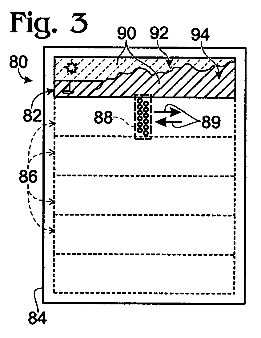
- Fig. 3 shows printed output 80 created by formation of an image portion 82 with reduced registration errors on a print medium 84.
- the image portion may be any suitable portion of a computer generated image (text, graphics, art, etc.), a photograph, and/or a digitized (or scanned) image (such as a picture, a drawing, a handwritten or printed document, etc.), among others.
- the image portion is a single-colorant portion of a multi-colorant image or may be a multi-colorant image portion.
- the print medium may be a sheet medium, such as paper, cardboard, plastic, fabric, metal, and/or glass, among others.
- the image portion may correspond to one of a set of output swaths 86, or to a portion(s) of an output swath(s), among others.
- Each output swath may be a segment accessed by travel of a printhead(s) 88 (shown in phantom outline) across a region adjacent the print medium.
- the swath may extend across any suitable region of the print medium.
- the swath may extend at least substantially (or completely) across the print medium, that is, to positions adjacent opposing edges of the print medium, or may extend any suitable portion thereof.
- the output swaths may be adjoining, but substantially nonoverlapping, as shown here.
- the output swaths may be overlapping, for example, produced by partially overlapping passes of the printhead.
- Each lighter area within each output swath (and thus of each image portion) may be formed with a subset (one or more) of a set of overlapping passes 89 of the printhead.
- Overlapping passes access overlapping regions of a medium.
- colorant may be delivered to different areas within the overlapping regions by the overlapping passes, so that the overlapping passes form interspersed (overlapping) sub-patterns of dots.
- the overlapping regions may be partially or completely overlapping. Accordingly, overlapping passes may be completely overlapping or partially overlapping.
- each pass of the set overlaps every other pass of the set.
- the image portion may be created with one colorant 90 or with a plurality of different colorants.
- the amounts (and densities) of the colorant in regions of image portion 82 are indicated in the present illustration according to the continuity (and weight) of hatch lines.
- Image portion 82 may include one or more lighter regions (or highlight regions) 92 (dashed lines) formed by lighter image areas 93 (a first subset of the image areas) with lesser amounts (and/or densities) of the colorant.
- Image portion 82 also may include one or more darker regions 94 (solid lines) formed by darker image areas 95 (a second subset of the image areas) with greater amounts (and/or densities) of the colorant.
- the lighter and darker regions each may have a range of colorant amounts defined for individual areas by the values of corresponding data elements (see below). Accordingly, the lesser amount and the greater amount of a colorant each may correspond to one amount, or, more generally, to a one or more smaller amounts and one or more larger amounts, respectively, of the colorant.
- Each region may have any suitable size and position.
- each of the regions (and their component areas) may be disposed in a single output swath. Accordingly, lighter and darker areas may be interspersed. Alternatively, the regions may be disposed in a plurality of output swaths, with lighter and darker regions disposed in the same or different swaths.
- Each area of a region may correspond to a single data element or to a plurality of adjacent data elements, such as a set of bi-level halftone data elements. Accordingly, lighter and darker areas may be defined based on each individual data element or based on a set of data elements (for example, by examining proximity, density, neighborhoods, etc).
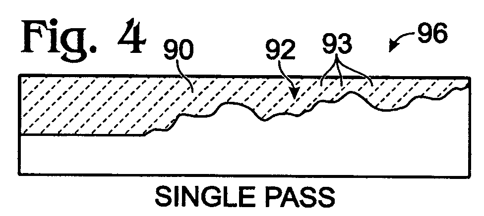
- Fig. 4 shows lighter region 92 produced by placement of colorant 90 during a single printhead pass 96 across a region adjacent the print medium to reduce registration errors within the lighter region.
- the subset of lighter areas 93 of the lighter region 92 may be created using fewer printhead passes (and/or fewer colorant placement structures) than to create the subset of darker areas 95 of the darker region 94.
- Fig. 5 shows darker region 94 produced by placement of colorant 90 during multiple printhead passes 98 across the print medium.
- One (or more) of the multiple passes may be the same pass(es) used to create lighter region 92 or areas thereof. Accordingly, a portion of darker region 94 may be created concurrently with lighter region 92.
- Darker region 94 may have no reduction in registration errors relative to pass assignment without identification of registration-sensitive areas. However, such registration errors may be less noticeable (and thus less of a problem) due to the higher density of colorant dots.
- Fig. 6 shows printed output 110 created by formation of image portion 82 with reduced registration errors on a print medium 84 during a single pass of two or more redundant printheads, such as printheads 112, 114.
- Redundant printheads 112, 114 may be configured to deliver the same or a similar colorant to overlapping (or the same) regions of print medium 84 as these printheads travel along the print medium, shown at 116. Alternatively, the print medium may move as the printheads remain stationary.
- each of printheads 112, 114 define an output swath 118 corresponding to the set of output swaths 86 of Fig. 3 and to the entire printed area. Similar to printed output 80 of Fig.
- lighter areas 93 may be printed during a single pass (one pass of one of the printheads, such as first printhead 112). Also, darker areas 95 may be printed during multiple printhead passes, for example, by a single pass of each of printheads 112, 114.
- Fig. 7 shows a flowchart illustrating a method 130 of forming images including image highlight regions.
- the method may be performed by any suitable image forming apparatus, as described above, alone or in combination with a computing device.
- the operations of the method shown may be performed in any suitable combination (i.e., one or more may be omitted) and in any suitable order.
- Method 130 may include an operation, shown at 132, of obtaining image data 134 defining a portion of an image.
- the operation of obtaining may include receiving the image data from a remote location, such as from a separate computing device and/or based on inputs from a person, among others.
- Image data 134 may be in any suitable format, such as a matrix 136 of contone data elements 138. A very small matrix of image data is shown here to simplify the presentation. However, the matrix may be of any suitable size.
- Each contone data element may correspond to an area within an image portion, for example, based on a row and column position 140 within the matrix of data elements.
- Each contone data element also may have a data value 142, such as a numerical value, represented here by an integer between zero and two-hundred and fifty-five, so the data value in this example may be one of two-hundred and fifty-six data values. More generally, a data element may have a data value selected from a set of at least two or more permissible values, and a contone data element may have a data value selected from a set of at least sixteen or more permissible values (such as consecutive integers). The data value of each data element may define an amount (and/or a density) of a colorant for an area of the image portion.
- Method 130 may include an operation, shown at 144, of converting the image data (rendering the data) to another form, such as multi-level halftone data 146 of data elements 148.
- Multi-level halftone data as used herein, has data elements with data values selected from a set of three or more permissible values and generally from a smaller set than a contone set of permissible values.
- Bi-level halftone data has data elements with data values selected from a set of two permissible values, generally zero and one.
- the data values 150 of the data elements of the multi-level halftone data may be selected from a smaller set of permissible values than for the contone values, producing a greater quantization of the data.
- data conversion converts a first set of data elements, each having one of two-hundred and fifty-six permissible values into a second set of data elements having one of four permissible values, the integers zero through three.
- contone values of 0-63 are set to "0”
- values of 64-127 are set to "1”
- values of 128-191 are set to "2”
- values of 192-255 are set to "3".
- Such conversion may be used to simplify contone data, for example, to select a number of colorant droplets to place on a print medium for each data element, and/or to identify data elements defining lighter and darker areas of an image portion.
- data conversion may include conversion of a contone form of the image data to a bi-level halftone form of the image data.
- data conversion may include any suitable modification to the simplified approach presented above, for example, to reduce systematic errors in data conversion. Accordingly, an error diffusion approach (such as distribution of an error term to adjacent pixels based on the difference between a pixel's contone (or halftone) value and the threshold), random thresholding, and/or a matrix-based approach, among others, may be used to reduce errors relative to the simplified approach presented above.
- Other data conversion may include an adjustment in the number of data elements in the matrix (for example, by duplication or deletion of data elements). An operation of data conversion may be performed before, during, and/or after the operation of obtaining data.
- Method 130 may include an operation, shown at 152, of analyzing the image data to identify data elements corresponding to lesser and greater amounts of colorant and thus corresponding to one or more lighter areas and one or more darker areas of the image portion.
- first subset 154 of data elements correspond to lighter areas 155 having a lesser, nonzero amount (or density) of colorant
- second subset 156 of data elements correspond to darker areas 157 having a greater amount (or density) of colorant. Identification of such data elements corresponding to lighter and darker areas of an image portion may be based on the data value of each data element individually and/or based on clustering of data elements having lower or higher data values.
- the analysis may be performed alternatively on a contone form 134 of the image data, a multi-level halftone form 146 of the image data, and/or on bi-level halftone data, among others.
- the data values of contone data elements or multi-level halftone data elements may be compared with a predefined threshold.
- the threshold is a halftone data value (or level) of one, so that halftone data elements having data values above one are deemed to define darker areas 157, and data elements having a data value of one are deemed to define lighter areas 155.
- the threshold may be set so that the lighter areas generally can be printed in one pass without exceeding any predefined printing constraints (such as limits on nozzle firing frequency, nozzle firing rate, droplet proximities, coalescence, etc.).
- Method 130 may include an operation, shown at 160, of distributing the image data to form distributed data 162 that has been apportioned to pass assignments 164, 166, 168.
- the operation of distributing may distribute portions 170 of the image data (and/or of individual data elements) to different pass assignments. Colorant placement defined by each data element may be assigned to a single pass assignment or to a plurality of pass assignments.
- Pass assignments 164, 166, 168 for portions of the image data are represented here schematically as implemented droplets 172, or masked droplets 174 for a series of overlapping pass configurations. Data corresponding to masked droplets 174 may be defined by a mask 176 and/or by an algorithm.
- Data elements defining lighter areas 155 of the image portion may be assigned for implementation in the same printhead pass, shown at 178 for pass number one, or to the same subset of printhead passes for an output swath.
- data elements defining darker areas 157 of the image portion may be assigned to be implemented in different subsets of printhead passes (compare droplet assignment within areas 180 and 182 in pass numbers one through three).
- Method 130 may include an operation, shown at 184, of placing a colorant according to distributed data 162 and thus according to pass assignments 164, 166, 168 during a plurality of printhead passes.
- pass assignments may be implemented by a single printhead performing a plurality of overlapping passes of a single printhead or by redundant printheads, each performing a single pass, among others.
Landscapes
- Engineering & Computer Science (AREA)
- Quality & Reliability (AREA)
- Ink Jet (AREA)
Abstract
Description
- Printers may create a portion of a printed image on a print medium by firing ink droplets of a particular color at the print medium. These ink droplets may be fired from a single printhead or from redundant printheads, among others, to create areas of the image portion. The areas may be created using ink placement during one or more printhead passes over the print medium.
- For some areas of an image portion, multiple printhead passes or redundant printheads may be used to form a higher density of the ink droplets. Otherwise, print quality may be affected adversely by exceeding, for example, the capacity of a printhead to deliver ink effectively in a single pass. However, the use of multiple passes or redundant printheads for creating these areas may produce substantial registration errors among different passes or printheads. Such registration errors may degrade a printed image by creating blurriness and/or graininess in the image.
-
- Fig. 1 is a view of an embodiment of a system for forming images, including image highlight regions, in accordance with an embodiment of the present teachings.
- Fig. 2 is a schematic view of the embodiment of the system of Fig. 1, in accordance with an embodiment of the present teachings.
- Fig. 3 is a plan view of printed output created by formation of an example image portion with reduced registration errors on a print medium using multiple passes of one printhead, in accordance with an embodiment of the present teachings.
- Fig. 4 is a view of a region of the example image portion of Fig. 3 composed of lighter areas having lesser amounts of a colorant and produced by placement of the colorant using only one pass of one printhead to reduce registration errors, in accordance with an embodiment of the present teachings.
- Fig. 5 is a view of another region of the example image portion of Fig. 3 composed of darker areas having greater amounts of the colorant and produced by placement of the colorant using multiple passes of one printhead, in accordance with an embodiment of the present teachings.
- Fig. 6 is a plan view of printed output created by formation of an example image portion with reduced registration errors on a print medium using only one pass of a set of redundant printheads, in accordance with an embodiment of the present teachings.
- Fig. 7 is a flowchart illustrating an embodiment of a method of forming images, including image highlight regions, in accordance with an embodiment of the present teachings.
-
- The present teachings provide systems, including apparatus and methods, for forming images, such as images including image highlight regions. The systems may obtain image data defining an image portion to be formed, such as an image portion to be formed with a colorant (or a plurality of colorants) and corresponding to a swath of printed output. The image data may include a set of data elements corresponding to areas of the image portion and defining an amount (and/or density) of the colorant for each area. In particular, the data elements may define a first subset of the areas having one or more lesser (nonzero) amounts (and/or densities) of the colorant. The first subset of the areas may be considered to be highlight regions of the image portion. The data elements also may define a second subset of the areas having one or more greater amounts (and/or densities) of the colorant. Each data element may have a data value corresponding to a particular one of the lesser or greater amounts (and/or densities) of the colorant for a corresponding area of the image portion. In some examples, the data values may be selected from a set of permissible values, such as a set of two or more permissible values, for example, a contone set of values or a halftone set of values, among others.
- The systems may distribute the image data to a set of pass assignments corresponding to a set of overlapping passes. Distribution may be performed so that the first subset of the areas (the highlight regions) will be formed completely by a subset of the overlapping passes and/or by a subset of structures (such as printheads and/or nozzles, among others) that are available to place the colorant for the overlapping passes. In some examples, distribution of the image data may be performed by applying one or more predefined masks to the image data. The predefined masks may be configured and applied so that a subset of the data elements, with data values selected from a subset of the permissible values, are assigned to a subset of the pass assignments and/or to particular positions within the pass assignments. These particular positions may correspond to a subset of the structures (such as nozzles) available to place the colorant. In some examples, distribution of the image data may be performed by comparing data values (such as contone data values) to a threshold(s) and distributing data elements to pass assignments and/or particular positions within pass assignments based on this comparison. In any case, the colorant then may be placed onto a medium to form the image portion with the set of overlapping passes corresponding to the pass assignments.
- The highlight regions of an image, because of a lower amount/density of colorant dots, may be more sensitive to problems related to image quality. These problems may include registration errors, noticeability of individual dots, and/or patterning created by the arrangement of dots in relation to unprinted areas. In addition, these problems may be more pronounced with use of multiple passes, use of multiple printheads, and/or use of particular regions of a printhead, among others. The highlight regions thus may be formed by colorant placement from a subset of a set of overlapping passes performed by one or more printheads, and/or by a subset of printheads (and/or nozzles thereof) available to place the colorant. Accordingly, by using fewer passes and/or fewer image forming structures (such as printheads and/or nozzles, among others) to form highlight regions, and in a particular embodiment by using one pass of one printhead to form these regions within a swath of printed output, overall image quality may be improved.
- The image forming systems may include apparatus configured to place visible image elements (such as dots) on a medium. The visible image elements may be formed with one or more colorants, such as inks, dyes, and/or other fluid or solid coloring agents. Colorants may impart any color (or colors) and/or color change(s), including black and/or white, to areas of a medium. Alternatively, or in addition, the visible image elements may be formed with one or more types of lights (colorant thus taking the form of light of different wavelengths), for example, by light projection or medium excitation, among others. Accordingly, the image forming systems may include a printing apparatus or printer (such as an inkjet printer, a laser printer, a plotter, or the like), a projector, a television, and/or a display, among others.
- Fig. 1 shows an example of a
system 10 for forming images including image highlight regions.System 10 may include an image forming apparatus, such as aprinter 12, configured to form images on (and/or in)medium 14.System 10 also may include acomputing device 16 in communication, shown at 18, with the printer. The computing device may be configured to send image data in any suitable form to the image forming apparatus. - The image forming apparatus may include one or more image forming structures or devices, such as one or
more printheads 20. Each printhead may be any device from which colorant(s) is dispensed to a print medium. In the present illustration,printheads 20 are included incolorant cartridges 22 serving as colorant reservoirs. In other embodiments, colorant reservoirs may be disposed in a spaced relation to their printheads, that is, off-axis. - The printhead(s) may be stationary or may move relative to the print medium. In the present illustration, the printheads are configured to reciprocate, in
opposing directions - The printer may be configured to move the print medium along a y-
axis 28, so that the printheads (whether movable along the x-axis or stationary) can access different segments of the print medium to form swaths of printed output (see Fig. 3). Alternatively, or in addition, the printer may be configured to move printheads along the y-axis as the print medium remains stationary. - Fig. 2 shows a schematic view of
system 10.Computing device 16 may be configured to send image (or print)data 40 defining an image portion toprinter 12. Alternatively, or in addition, the computing device may be configured to parse data into sets of image data corresponding to individual output swaths, analyze the image data to identify areas of lesser and greater colorant amounts in the corresponding image portion, and/or distribute the image data so that subsets of data elements are used to form image elements during particular passes, among others. However, in the present illustration,printer 12 is configured to perform these and other tasks that may be assigned alternatively, or in addition, to computingdevice 16. -
Printer 12 may include acontroller 42 and a colorant placement portion 44.Controller 42 may be configured to receiveimage data 40 fromcomputing device 16 and process the image data into printing instructions for the colorant placement portion. As part of this processing, the controller may distribute image data to pass assignments so that highlight regions of an image portion are printed by a subset of a set of overlapping passes used for forming the image portion and/or by a subset of printing structures available to place the colorant. Colorant placement portion 44 may be configured to dispense colorant positionally during passes selected by the printer controller. -
Controller 42 may include aprinter processor 46 and printer memory 48. The printer processor may be configured to perform manipulation of image data received from the computing device and/or from the printer memory, including logic and/or arithmetic operations, among others. Processing of the image data may be performed based on processing instructions for the image data. Such processing instructions may be contained in printer memory 48 (such as hardware, firmware, and/or software, among others) and may include a data translator andparser 50, and adata distribution mechanism 52, among others. - Data translator and
parser 50 may be any mechanism(s) for translating the image data into a different form(s) and/or parsing the image data into instructions for individual printed swaths (see Fig. 3). Data translation (or rendering) may include conversion of the image data into a page description language, conversion of contone data into a more quantized form (such as multi-level halftone data or binary halftone data; see Fig. 7), and/or conversion of image data to a different resolution, among others. -
Data distribution mechanism 52 may be any mechanism for distributing the image data to a set of pass assignments. Pass assignments, as used herein, are portions of the image data designated to instruct colorant placement during corresponding passes. The portions of the image data, when summed over the pass assignments, may at least substantially equal the image data. The data distribution mechanism may include adata analysis mechanism 54 and/or amask application mechanism 56, among others. -
Data analysis mechanism 54 may be any mechanism for distribution of the image data to pass assignments based on the image data itself. Accordingly, the data analysis mechanism may be configured to examine the image data to identify data elements corresponding to image areas with lesser and/or greater amounts of a colorant. The data analysis mechanism may analyze data values of individual data elements or the data values of sets of data elements, such as pixel neighborhoods. This data analysis, and distribution of the image data based on this analysis, may be performed, for example, with one ormore algorithms 58 configured for this purpose.Algorithm 58 may operate to distribute the image data to pass assignments without predefined masks. The algorithm may distribute the image data to pass assignments, by directly selecting subsets of the image data, without application of a distinct mask. For example, the algorithm may include a rule which causes specified image data levels (values) or identified areas of image data to be assigned to a particular subset of pass assignments. Alternatively, masks may be created based on the analysis of the image data, and then applied to the image data. Exemplary data analysis and data distribution based on this analysis are described below in relation to Fig. 7. -
Mask application mechanism 56 may be used as an alternative to, or in addition to,data analysis mechanism 54. Themask application mechanism 54 may be any mechanism for maskingimage data 40 using one or morepredefined masks 60. A mask, as used herein, is a spatial pattern that is logically compared to image data to assign a portion of the image data to a particular pass assignment for implementation during a corresponding pass. Masks may be designed as a complementary set, such that among a set of masks, all image data may be distributed to a set of pass assignments and thus properly printed during a corresponding set of passes. The mask may be predefined, that is, constructed independently of the content of the image data, so that the highlight regions are formed by a particular subset of overlapping passes and/or by a subset of available colorant placement structures. The mask application mechanism may distribute the image data to pass assignments corresponding to a plurality of overlapping passes that create an output swath. As part of this masking process, some data values may be set to a null value (generally zero) to "mask" the corresponding data element so that this data element is not implemented in a particular pass (or passes). - Colorant placement portion 44 may include a
printhead movement mechanism 62, amedia advancement mechanism 64, and a set of image forming structures 66, such asprintheads 20 and/or nozzles.Printhead movement mechanism 62 may cause the printhead to reciprocate, as illustrated in Figure 1. Alternatively, or in addition, the printhead movement mechanism may move the printhead in any other suitable direction(s), including two or three orthogonal directions, among others, or may be omitted from the printer.Media advancement mechanism 64 may move print media along an axis orthogonal to the axis defined by the printhead movement mechanism. In some embodiments, the printhead movement mechanism may perform the function of the media advancement mechanism by moving orthogonally. Alternatively, or in addition, the media advancement mechanism may move the media in orthogonal directions. - Image forming structures 66 may be any structures from which a particular colorant may be placed. Accordingly, the structures may be one or
more printheads 20 configured to deliver the colorant. In some examples, a particular colorant may be delivered from two or more substantially redundant printheads configured to access overlapping and/or identical sections of a print medium (see Fig. 6). Printhead(s) may include firingelements 68, such as heater elements or piezoelectric elements. The firing elements may operate to expel colorant droplets from any array of image forming structures, such asnozzles 70, and onto a print medium. In some examples, image highlight regions may be formed by a subset of the nozzles, such as nozzles with a particular position and/or configuration within a printhead. The particular position may be, for example, a central set of rows of nozzles within an array of nozzles (to avoid printhead end effects), nozzles restricted to a subset of columns within an array of nozzles, a subset of nozzles having a distinct orifice size and/or associated with a distinct type of firing element, and/or the like. - Fig. 3 shows printed
output 80 created by formation of animage portion 82 with reduced registration errors on aprint medium 84. The image portion may be any suitable portion of a computer generated image (text, graphics, art, etc.), a photograph, and/or a digitized (or scanned) image (such as a picture, a drawing, a handwritten or printed document, etc.), among others. In some examples, the image portion is a single-colorant portion of a multi-colorant image or may be a multi-colorant image portion. The print medium may be a sheet medium, such as paper, cardboard, plastic, fabric, metal, and/or glass, among others. - The image portion may correspond to one of a set of
output swaths 86, or to a portion(s) of an output swath(s), among others. Each output swath may be a segment accessed by travel of a printhead(s) 88 (shown in phantom outline) across a region adjacent the print medium. The swath may extend across any suitable region of the print medium. For example, the swath may extend at least substantially (or completely) across the print medium, that is, to positions adjacent opposing edges of the print medium, or may extend any suitable portion thereof. The output swaths may be adjoining, but substantially nonoverlapping, as shown here. Alternatively, the output swaths may be overlapping, for example, produced by partially overlapping passes of the printhead. Each lighter area within each output swath (and thus of each image portion) may be formed with a subset (one or more) of a set of overlapping passes 89 of the printhead. Overlapping passes, as used herein, access overlapping regions of a medium. However, colorant may be delivered to different areas within the overlapping regions by the overlapping passes, so that the overlapping passes form interspersed (overlapping) sub-patterns of dots. The overlapping regions may be partially or completely overlapping. Accordingly, overlapping passes may be completely overlapping or partially overlapping. For a set of overlapping passes, as used herein, each pass of the set overlaps every other pass of the set. - The image portion may be created with one
colorant 90 or with a plurality of different colorants. The amounts (and densities) of the colorant in regions ofimage portion 82 are indicated in the present illustration according to the continuity (and weight) of hatch lines.Image portion 82 may include one or more lighter regions (or highlight regions) 92 (dashed lines) formed by lighter image areas 93 (a first subset of the image areas) with lesser amounts (and/or densities) of the colorant.Image portion 82 also may include one or more darker regions 94 (solid lines) formed by darker image areas 95 (a second subset of the image areas) with greater amounts (and/or densities) of the colorant. The lighter and darker regions each may have a range of colorant amounts defined for individual areas by the values of corresponding data elements (see below). Accordingly, the lesser amount and the greater amount of a colorant each may correspond to one amount, or, more generally, to a one or more smaller amounts and one or more larger amounts, respectively, of the colorant. - Each region may have any suitable size and position. In some examples, each of the regions (and their component areas) may be disposed in a single output swath. Accordingly, lighter and darker areas may be interspersed. Alternatively, the regions may be disposed in a plurality of output swaths, with lighter and darker regions disposed in the same or different swaths. Each area of a region may correspond to a single data element or to a plurality of adjacent data elements, such as a set of bi-level halftone data elements. Accordingly, lighter and darker areas may be defined based on each individual data element or based on a set of data elements (for example, by examining proximity, density, neighborhoods, etc).
- Fig. 4 shows
lighter region 92 produced by placement ofcolorant 90 during asingle printhead pass 96 across a region adjacent the print medium to reduce registration errors within the lighter region. In some examples, the subset oflighter areas 93 of thelighter region 92 may be created using fewer printhead passes (and/or fewer colorant placement structures) than to create the subset ofdarker areas 95 of thedarker region 94. - Fig. 5 shows
darker region 94 produced by placement ofcolorant 90 during multiple printhead passes 98 across the print medium. One (or more) of the multiple passes may be the same pass(es) used to createlighter region 92 or areas thereof. Accordingly, a portion ofdarker region 94 may be created concurrently withlighter region 92.Darker region 94 may have no reduction in registration errors relative to pass assignment without identification of registration-sensitive areas. However, such registration errors may be less noticeable (and thus less of a problem) due to the higher density of colorant dots. - Fig. 6 shows printed
output 110 created by formation ofimage portion 82 with reduced registration errors on aprint medium 84 during a single pass of two or more redundant printheads, such asprintheads 112, 114.Redundant printheads 112, 114 may be configured to deliver the same or a similar colorant to overlapping (or the same) regions ofprint medium 84 as these printheads travel along the print medium, shown at 116. Alternatively, the print medium may move as the printheads remain stationary. In the present illustration, each ofprintheads 112, 114 define anoutput swath 118 corresponding to the set ofoutput swaths 86 of Fig. 3 and to the entire printed area. Similar to printedoutput 80 of Fig. 3,lighter areas 93 may be printed during a single pass (one pass of one of the printheads, such as first printhead 112). Also,darker areas 95 may be printed during multiple printhead passes, for example, by a single pass of each ofprintheads 112, 114. - Fig. 7 shows a flowchart illustrating a
method 130 of forming images including image highlight regions. The method may be performed by any suitable image forming apparatus, as described above, alone or in combination with a computing device. The operations of the method shown may be performed in any suitable combination (i.e., one or more may be omitted) and in any suitable order. -
Method 130 may include an operation, shown at 132, of obtainingimage data 134 defining a portion of an image. The operation of obtaining may include receiving the image data from a remote location, such as from a separate computing device and/or based on inputs from a person, among others.Image data 134 may be in any suitable format, such as amatrix 136 ofcontone data elements 138. A very small matrix of image data is shown here to simplify the presentation. However, the matrix may be of any suitable size. Each contone data element may correspond to an area within an image portion, for example, based on a row andcolumn position 140 within the matrix of data elements. Each contone data element also may have adata value 142, such as a numerical value, represented here by an integer between zero and two-hundred and fifty-five, so the data value in this example may be one of two-hundred and fifty-six data values. More generally, a data element may have a data value selected from a set of at least two or more permissible values, and a contone data element may have a data value selected from a set of at least sixteen or more permissible values (such as consecutive integers). The data value of each data element may define an amount (and/or a density) of a colorant for an area of the image portion. -
Method 130 may include an operation, shown at 144, of converting the image data (rendering the data) to another form, such asmulti-level halftone data 146 ofdata elements 148. Multi-level halftone data, as used herein, has data elements with data values selected from a set of three or more permissible values and generally from a smaller set than a contone set of permissible values. Bi-level halftone data has data elements with data values selected from a set of two permissible values, generally zero and one. - The data values 150 of the data elements of the multi-level halftone data may be selected from a smaller set of permissible values than for the contone values, producing a greater quantization of the data. For example, in the present illustration, data conversion converts a first set of data elements, each having one of two-hundred and fifty-six permissible values into a second set of data elements having one of four permissible values, the integers zero through three. In the present example, contone values of 0-63 are set to "0", values of 64-127 are set to "1", values of 128-191 are set to "2", and values of 192-255 are set to "3". Such conversion may be used to simplify contone data, for example, to select a number of colorant droplets to place on a print medium for each data element, and/or to identify data elements defining lighter and darker areas of an image portion. Alternatively, or in addition, data conversion may include conversion of a contone form of the image data to a bi-level halftone form of the image data. In any case, data conversion may include any suitable modification to the simplified approach presented above, for example, to reduce systematic errors in data conversion. Accordingly, an error diffusion approach (such as distribution of an error term to adjacent pixels based on the difference between a pixel's contone (or halftone) value and the threshold), random thresholding, and/or a matrix-based approach, among others, may be used to reduce errors relative to the simplified approach presented above. Other data conversion may include an adjustment in the number of data elements in the matrix (for example, by duplication or deletion of data elements). An operation of data conversion may be performed before, during, and/or after the operation of obtaining data.
-
Method 130 may include an operation, shown at 152, of analyzing the image data to identify data elements corresponding to lesser and greater amounts of colorant and thus corresponding to one or more lighter areas and one or more darker areas of the image portion. In the present illustration,first subset 154 of data elements (dashed hatch lines) correspond tolighter areas 155 having a lesser, nonzero amount (or density) of colorant, andsecond subset 156 of data elements (solid hatch lines) correspond todarker areas 157 having a greater amount (or density) of colorant. Identification of such data elements corresponding to lighter and darker areas of an image portion may be based on the data value of each data element individually and/or based on clustering of data elements having lower or higher data values. Accordingly, the analysis may be performed alternatively on acontone form 134 of the image data, amulti-level halftone form 146 of the image data, and/or on bi-level halftone data, among others. In some examples, the data values of contone data elements or multi-level halftone data elements may be compared with a predefined threshold. In the present illustration, the threshold is a halftone data value (or level) of one, so that halftone data elements having data values above one are deemed to definedarker areas 157, and data elements having a data value of one are deemed to definelighter areas 155. In some examples, the threshold may be set so that the lighter areas generally can be printed in one pass without exceeding any predefined printing constraints (such as limits on nozzle firing frequency, nozzle firing rate, droplet proximities, coalescence, etc.). -
Method 130 may include an operation, shown at 160, of distributing the image data to form distributeddata 162 that has been apportioned to passassignments portions 170 of the image data (and/or of individual data elements) to different pass assignments. Colorant placement defined by each data element may be assigned to a single pass assignment or to a plurality of pass assignments. Passassignments droplets 172, ormasked droplets 174 for a series of overlapping pass configurations. Data corresponding tomasked droplets 174 may be defined by amask 176 and/or by an algorithm. Data elements defininglighter areas 155 of the image portion, which are more sensitive to registration errors, may be assigned for implementation in the same printhead pass, shown at 178 for pass number one, or to the same subset of printhead passes for an output swath. In contrast, data elements definingdarker areas 157 of the image portion, which are less sensitive to registration errors produced between two or more passes, may be assigned to be implemented in different subsets of printhead passes (compare droplet assignment withinareas -
Method 130 may include an operation, shown at 184, of placing a colorant according to distributeddata 162 and thus according to passassignments - It is believed that the disclosure set forth above encompasses multiple distinct embodiments of the invention. While each of these embodiments has been disclosed in specific form, the specific embodiments thereof as disclosed and illustrated herein are not to be considered in a limiting sense as numerous variations are possible. The subject matter of this disclosure thus includes all novel and non-obvious combinations and subcombinations of the various elements, features, functions and/or properties disclosed herein. Similarly, where the claims recite "a" or "a first" element or the equivalent thereof, such claims should be understood to include incorporation of one or more such elements, neither requiring nor excluding two or more such elements.
Claims (10)
- A method of forming images, comprising: obtaining image data (134) defining an image portion (82) and including data elements (138) defining a first subset (93) and a second subset (95) of areas of the image portion (82) having one or more lesser amounts and one or more greater amounts, respectively, of a colorant (90); and forming the image portion (82) by placement of the colorant (90) onto a medium (84) during a set of overlapping passes (89) so that the first subset (93) of the areas is formed by at least one of (a) a subset of the overlapping passes (89) and (b) a predefined subset of a plurality of structures (66) available for placing the colorant (90).
- The method of claim 1, wherein each data element (138) includes a data value (150) defining an amount of the colorant (90), and wherein the image data (134) is in a contone form, the method further comprising analyzing the contone form of the image data (134) to identify a subset of the data elements (138) having data values (150) corresponding to a subset of permissible values, and wherein the subset of the data elements (138) corresponds to the first subset (93) of the areas.
- The method of any of claims 1-2, wherein the structures (66) are a plurality of printheads (112, 114), and wherein forming is performed so that the first subset (93) of the areas is formed by a subset of the plurality of printheads (112,114).
- The method of any of claims 1-2, wherein the structures (66) are a plurality of nozzles (70), and wherein forming includes forming the first subset (93) of the areas with a predefined subset of the plurality of nozzles (70).
- The method of any of claims 1-2, wherein one printhead (88) is available to place the colorant (90), and wherein forming includes forming the first subset (93) of the areas with the one printhead (88) during the subset of overlapping passes (89).
- The method of any of claims 1-5, wherein obtaining includes obtaining image data (134) corresponding to an output swath (86) of the colorant (90).
- The method of any of claims 1-6, which further comprises distributing the image data (134) to pass assignments (164, 166, 168) corresponding to the set of overlapping passes (89), and wherein forming includes placing the colorant (90) during the set of overlapping passes (89) according to the pass assignments (164, 166, 168), and wherein distributing includes applying one or more predefined masks (60) to the image data (134).
- The method of claim 7, wherein each data element (138) includes a data value (150) defining an amount of the colorant (90), wherein obtaining image data (134) includes (a) obtaining a first form of the image data (134) with data values (150) selected from a larger set of permissible values, and (b) converting the first form to a second form of the image data (134) having data values (150) selected from a smaller set of permissible values, and wherein distributing is performed with the second form of the image data (134).
- The method of any of claims 1 and 3-7, wherein obtaining image data includes obtaining image data in a binary halftone form.
- A system configured to form images using any of the methods of claims 1-9.
Applications Claiming Priority (2)
| Application Number | Priority Date | Filing Date | Title |
|---|---|---|---|
| US814724 | 2004-03-30 | ||
| US10/814,724 US7168784B2 (en) | 2004-03-30 | 2004-03-30 | Formation of images |
Publications (2)
| Publication Number | Publication Date |
|---|---|
| EP1582358A1 true EP1582358A1 (en) | 2005-10-05 |
| EP1582358B1 EP1582358B1 (en) | 2011-11-02 |
Family
ID=34887723
Family Applications (1)
| Application Number | Title | Priority Date | Filing Date |
|---|---|---|---|
| EP05251800A Expired - Fee Related EP1582358B1 (en) | 2004-03-30 | 2005-03-23 | Formation of images |
Country Status (2)
| Country | Link |
|---|---|
| US (1) | US7168784B2 (en) |
| EP (1) | EP1582358B1 (en) |
Cited By (1)
| Publication number | Priority date | Publication date | Assignee | Title |
|---|---|---|---|---|
| WO2025023197A1 (en) * | 2023-07-26 | 2025-01-30 | コニカミノルタ株式会社 | Image formation method |
Families Citing this family (56)
| Publication number | Priority date | Publication date | Assignee | Title |
|---|---|---|---|---|
| GB0221464D0 (en) | 2002-09-16 | 2002-10-23 | Cambridge Internetworking Ltd | Network interface and protocol |
| GB0304807D0 (en) * | 2003-03-03 | 2003-04-09 | Cambridge Internetworking Ltd | Data protocol |
| GB0404696D0 (en) | 2004-03-02 | 2004-04-07 | Level 5 Networks Ltd | Dual driver interface |
| GB0408876D0 (en) | 2004-04-21 | 2004-05-26 | Level 5 Networks Ltd | User-level stack |
| GB0408868D0 (en) | 2004-04-21 | 2004-05-26 | Level 5 Networks Ltd | Checking data integrity |
| GB0505297D0 (en) | 2005-03-15 | 2005-04-20 | Level 5 Networks Ltd | Redirecting instructions |
| GB0505300D0 (en) | 2005-03-15 | 2005-04-20 | Level 5 Networks Ltd | Transmitting data |
| EP3217285B1 (en) | 2005-03-10 | 2021-04-28 | Xilinx, Inc. | Transmitting data |
| GB0506403D0 (en) | 2005-03-30 | 2005-05-04 | Level 5 Networks Ltd | Routing tables |
| US7634584B2 (en) | 2005-04-27 | 2009-12-15 | Solarflare Communications, Inc. | Packet validation in virtual network interface architecture |
| DE602006013128D1 (en) | 2005-06-15 | 2010-05-06 | Solarflare Comm Inc | RECEIVING DATA ACCORDING TO A DATA TRANSFER PROTOCOL OF DATA FOCUSED ON ANY ONE MULTIPLE OF RECEIPT EQUIPMENT |
| US7984180B2 (en) | 2005-10-20 | 2011-07-19 | Solarflare Communications, Inc. | Hashing algorithm for network receive filtering |
| GB0600417D0 (en) | 2006-01-10 | 2006-02-15 | Level 5 Networks Inc | Virtualisation support |
| US7967407B2 (en) * | 2006-02-03 | 2011-06-28 | R.R. Donnelley | Use of a sense mark to control a printing system |
| US8116312B2 (en) | 2006-02-08 | 2012-02-14 | Solarflare Communications, Inc. | Method and apparatus for multicast packet reception |
| US9948533B2 (en) | 2006-07-10 | 2018-04-17 | Solarflare Communitations, Inc. | Interrupt management |
| US9686117B2 (en) | 2006-07-10 | 2017-06-20 | Solarflare Communications, Inc. | Chimney onload implementation of network protocol stack |
| EP2632109B1 (en) * | 2006-07-10 | 2017-05-10 | Solarflare Communications Inc | Data processing system and method therefor |
| US7497538B2 (en) * | 2006-08-08 | 2009-03-03 | Lexmark International, Inc. | Method of multipass printing using a plurality of halftone patterns of dots |
| GB0621774D0 (en) * | 2006-11-01 | 2006-12-13 | Level 5 Networks Inc | Driver level segmentation |
| US8289538B2 (en) * | 2007-03-28 | 2012-10-16 | Moore Wallace North America, Inc. | Systems and methods for managing print jobs |
| US8753026B2 (en) | 2007-06-29 | 2014-06-17 | R.R. Donnelley & Sons Company | Use of a sense mark to control a printing system |
| US8184304B2 (en) * | 2007-11-19 | 2012-05-22 | Moore Wallace North America, Inc. | System and method of operating a raster image processor |
| GB0723422D0 (en) | 2007-11-29 | 2008-01-09 | Level 5 Networks Inc | Virtualised receive side scaling |
| US8564808B2 (en) * | 2007-12-18 | 2013-10-22 | R. R. Donnelley & Sons Company | Systems and methods for processing of variable documents |
| GB0802126D0 (en) * | 2008-02-05 | 2008-03-12 | Level 5 Networks Inc | Scalable sockets |
| US8390829B2 (en) * | 2008-09-30 | 2013-03-05 | Eastman Kodak Company | Inkjet printing method using print modes selected in response to image quality scores |
| US20100110467A1 (en) * | 2008-11-06 | 2010-05-06 | Coniglio Paul A | System and Method of Rasterizing PDF Files using Multiple Processors |
| GB0823162D0 (en) * | 2008-12-18 | 2009-01-28 | Solarflare Communications Inc | Virtualised Interface Functions |
| US9098903B2 (en) | 2009-07-21 | 2015-08-04 | R.R. Donnelley & Sons Company | Systems and methods for detecting alignment errors |
| US9256560B2 (en) * | 2009-07-29 | 2016-02-09 | Solarflare Communications, Inc. | Controller integration |
| US9210140B2 (en) | 2009-08-19 | 2015-12-08 | Solarflare Communications, Inc. | Remote functionality selection |
| EP2309680B1 (en) * | 2009-10-08 | 2017-07-19 | Solarflare Communications Inc | Switching API |
| US8743877B2 (en) * | 2009-12-21 | 2014-06-03 | Steven L. Pope | Header processing engine |
| US9258390B2 (en) | 2011-07-29 | 2016-02-09 | Solarflare Communications, Inc. | Reducing network latency |
| US9674318B2 (en) | 2010-12-09 | 2017-06-06 | Solarflare Communications, Inc. | TCP processing for devices |
| US8996644B2 (en) | 2010-12-09 | 2015-03-31 | Solarflare Communications, Inc. | Encapsulated accelerator |
| US9600429B2 (en) | 2010-12-09 | 2017-03-21 | Solarflare Communications, Inc. | Encapsulated accelerator |
| US10873613B2 (en) | 2010-12-09 | 2020-12-22 | Xilinx, Inc. | TCP processing for devices |
| US9008113B2 (en) | 2010-12-20 | 2015-04-14 | Solarflare Communications, Inc. | Mapped FIFO buffering |
| US9384071B2 (en) | 2011-03-31 | 2016-07-05 | Solarflare Communications, Inc. | Epoll optimisations |
| US8763018B2 (en) | 2011-08-22 | 2014-06-24 | Solarflare Communications, Inc. | Modifying application behaviour |
| EP2574000B1 (en) | 2011-09-22 | 2020-04-08 | Xilinx, Inc. | Message acceleration |
| US8870326B2 (en) * | 2011-10-19 | 2014-10-28 | Hewlett-Packard Development Company, L.P. | Printing near saturation |
| US9391840B2 (en) | 2012-05-02 | 2016-07-12 | Solarflare Communications, Inc. | Avoiding delayed data |
| US9391841B2 (en) | 2012-07-03 | 2016-07-12 | Solarflare Communications, Inc. | Fast linkup arbitration |
| US20140063105A1 (en) * | 2012-09-04 | 2014-03-06 | Douglas Wayne Couwenhoven | Inkjet printing method using mode switching |
| US10505747B2 (en) | 2012-10-16 | 2019-12-10 | Solarflare Communications, Inc. | Feed processing |
| US10742604B2 (en) | 2013-04-08 | 2020-08-11 | Xilinx, Inc. | Locked down network interface |
| US9426124B2 (en) | 2013-04-08 | 2016-08-23 | Solarflare Communications, Inc. | Locked down network interface |
| EP2809033B1 (en) | 2013-05-30 | 2018-03-21 | Solarflare Communications Inc | Packet capture in a network |
| US10394751B2 (en) | 2013-11-06 | 2019-08-27 | Solarflare Communications, Inc. | Programmed input/output mode |
| JP6670150B2 (en) * | 2016-03-30 | 2020-03-18 | 理想科学工業株式会社 | Inkjet printing equipment |
| US10370214B2 (en) | 2017-05-31 | 2019-08-06 | Cryovac, Llc | Position control system and method |
| WO2021236107A1 (en) * | 2020-05-22 | 2021-11-25 | Purdue Research Foundation | Fiducial patterns |
| US20250209289A1 (en) | 2022-04-01 | 2025-06-26 | Eco3 Bv | Rendering a Color Separation |
Citations (3)
| Publication number | Priority date | Publication date | Assignee | Title |
|---|---|---|---|---|
| EP0863479A2 (en) * | 1997-03-04 | 1998-09-09 | Hewlett-Packard Company | Method and apparatus for multipass colour ink jet printing |
| US20030063140A1 (en) * | 2001-10-02 | 2003-04-03 | Nguyen Trung Vu | Printing system and method using page stitching for printing on roll media |
| US20040021732A1 (en) * | 2002-07-19 | 2004-02-05 | Bergen Patrick Van Den | Printing methods and apparatus for multi-pass printing |
Family Cites Families (19)
| Publication number | Priority date | Publication date | Assignee | Title |
|---|---|---|---|---|
| JPS648488A (en) | 1987-06-30 | 1989-01-12 | Sharp Kk | Image signal binarizing device |
| JPH06121161A (en) | 1991-05-14 | 1994-04-28 | Fuji Xerox Co Ltd | Character processing system for color image processor |
| US5270837A (en) | 1991-09-27 | 1993-12-14 | Apple Computer, Inc. | Method and apparatus for enabling intelligent post-processing of differing data types |
| US5625460A (en) | 1993-12-09 | 1997-04-29 | Eastman Kodak Company | Method and apparatus for locally switching gray dot types to reproduce an image with gray level printing |
| US5992962A (en) | 1994-12-22 | 1999-11-30 | Hewlett-Packard Company | Print masks for inkjet printers |
| US5714990A (en) | 1995-01-03 | 1998-02-03 | Xerox Corporation | Optimizing printing speed and managing printed sheet ejection based on image density and method of determining density |
| DE19513105A1 (en) | 1995-04-07 | 1996-10-10 | Hell Ag Linotype | Procedure for generating a contone map |
| JP3576694B2 (en) | 1996-04-23 | 2004-10-13 | キヤノン株式会社 | Ink jet recording method, apparatus thereof, image processing method, and printing method for executing image processing method |
| US5949964A (en) | 1997-06-17 | 1999-09-07 | Hewlett-Packard Company | Method and apparatus for halftoning of images in a printer |
| JP4040161B2 (en) | 1998-04-03 | 2008-01-30 | キヤノン株式会社 | Print positioning method and printing apparatus |
| JP3738566B2 (en) | 1998-08-05 | 2006-01-25 | コニカミノルタビジネステクノロジーズ株式会社 | Halftone image discrimination method and image processing apparatus |
| DE69905007T2 (en) | 1999-02-17 | 2003-11-06 | Hewlett-Packard Co. (N.D.Ges.D.Staates Delaware), Palo Alto | Multi-pass printing |
| US6302522B1 (en) | 2000-05-12 | 2001-10-16 | Xerox Corporation | Performance optimization of monochrome pages in a color printing system |
| US6481818B1 (en) | 2000-08-14 | 2002-11-19 | Hewlett-Packard Company | Method and facility for preventing overheating of a thermal ink jet print head |
| US6454389B1 (en) | 2000-09-11 | 2002-09-24 | Eastman Kodak Company | Multipass inkjet printing using print masking |
| JP2002222070A (en) | 2000-11-21 | 2002-08-09 | Canon Inc | Print data processing apparatus, print control method, and print control program |
| US6543871B1 (en) * | 2000-11-21 | 2003-04-08 | Electronics For Imaging, Inc. | Mask generator and image mask patterns |
| US6425653B1 (en) | 2000-12-07 | 2002-07-30 | Xerox Corporation | Single pass printing of text among interleaved printing of non-text material |
| EP1257113A3 (en) * | 2001-05-11 | 2006-04-12 | Seiko Epson Corporation | Printing with multiple pixels as a unit of gradation reproduction |
-
2004
- 2004-03-30 US US10/814,724 patent/US7168784B2/en not_active Expired - Fee Related
-
2005
- 2005-03-23 EP EP05251800A patent/EP1582358B1/en not_active Expired - Fee Related
Patent Citations (3)
| Publication number | Priority date | Publication date | Assignee | Title |
|---|---|---|---|---|
| EP0863479A2 (en) * | 1997-03-04 | 1998-09-09 | Hewlett-Packard Company | Method and apparatus for multipass colour ink jet printing |
| US20030063140A1 (en) * | 2001-10-02 | 2003-04-03 | Nguyen Trung Vu | Printing system and method using page stitching for printing on roll media |
| US20040021732A1 (en) * | 2002-07-19 | 2004-02-05 | Bergen Patrick Van Den | Printing methods and apparatus for multi-pass printing |
Cited By (1)
| Publication number | Priority date | Publication date | Assignee | Title |
|---|---|---|---|---|
| WO2025023197A1 (en) * | 2023-07-26 | 2025-01-30 | コニカミノルタ株式会社 | Image formation method |
Also Published As
| Publication number | Publication date |
|---|---|
| US7168784B2 (en) | 2007-01-30 |
| US20050219314A1 (en) | 2005-10-06 |
| EP1582358B1 (en) | 2011-11-02 |
Similar Documents
| Publication | Publication Date | Title |
|---|---|---|
| US7168784B2 (en) | Formation of images | |
| US20050219278A1 (en) | Image formation with a flexible number of passes | |
| US10507647B1 (en) | Methods and systems for compensating for a malfunctioning nozzle in a digital printing system | |
| US8287066B2 (en) | Ink jet printing method | |
| US11778123B2 (en) | Artifact compensation mechanism | |
| US6505905B1 (en) | Halftoning method and apparatus | |
| US9144998B2 (en) | Printing method and printing apparatus | |
| US6161919A (en) | Ink coverage reduction method for printers capable of printing multiple drop sizes | |
| US11783150B2 (en) | Artifact compensation mechanism | |
| JP4736766B2 (en) | Printing apparatus, printing program, printing method and image processing apparatus, image processing program, image processing method, and recording medium recording the program | |
| US20080150979A1 (en) | Ink jet printing apparatus and ink jet printing method | |
| US10562318B2 (en) | Method and system for compensating for a malfunctioning nozzle | |
| CN102756555B (en) | Inkjet printing apparatus and print data generating method | |
| EP0998126B1 (en) | Reduction of banding in incremental printing, through selection among colorimetric equivalents | |
| US8169666B2 (en) | Threshold matrix generation method, halftone image generation method, and halftone image generating apparatus | |
| US7637585B2 (en) | Halftone printing on an inkjet printer | |
| US6886912B2 (en) | Method and apparatus for processing images having color combinations | |
| US6106102A (en) | Odd number of passes, odd number of advances, and separated-diagonal-line masking, in liquid-ink printers | |
| US6491374B1 (en) | Methods and apparatuses for printing with uniform and non-uniform print mask functions | |
| JP6815511B2 (en) | Image processing equipment and methods, programs and image recording equipment | |
| JP2017185638A (en) | Droplet discharge controller, droplet discharge control method, and droplet discharge device | |
| US10124591B2 (en) | Printer and head unit | |
| EP2659435B1 (en) | Ink jet printing method | |
| US8649060B2 (en) | Method of halftoning for asymmetric print resolutions and a printer | |
| US12045521B1 (en) | Halftone modification mechanism |
Legal Events
| Date | Code | Title | Description |
|---|---|---|---|
| PUAI | Public reference made under article 153(3) epc to a published international application that has entered the european phase |
Free format text: ORIGINAL CODE: 0009012 |
|
| AK | Designated contracting states |
Kind code of ref document: A1 Designated state(s): AT BE BG CH CY CZ DE DK EE ES FI FR GB GR HU IE IS IT LI LT LU MC NL PL PT RO SE SI SK TR |
|
| AX | Request for extension of the european patent |
Extension state: AL BA HR LV MK YU |
|
| 17P | Request for examination filed |
Effective date: 20051024 |
|
| AKX | Designation fees paid |
Designated state(s): DE NL |
|
| 17Q | First examination report despatched |
Effective date: 20071106 |
|
| GRAC | Information related to communication of intention to grant a patent modified |
Free format text: ORIGINAL CODE: EPIDOSCIGR1 |
|
| GRAP | Despatch of communication of intention to grant a patent |
Free format text: ORIGINAL CODE: EPIDOSNIGR1 |
|
| GRAS | Grant fee paid |
Free format text: ORIGINAL CODE: EPIDOSNIGR3 |
|
| GRAA | (expected) grant |
Free format text: ORIGINAL CODE: 0009210 |
|
| AK | Designated contracting states |
Kind code of ref document: B1 Designated state(s): DE NL |
|
| REG | Reference to a national code |
Ref country code: NL Ref legal event code: T3 |
|
| REG | Reference to a national code |
Ref country code: DE Ref legal event code: R096 Ref document number: 602005030920 Country of ref document: DE Effective date: 20120202 |
|
| PLBE | No opposition filed within time limit |
Free format text: ORIGINAL CODE: 0009261 |
|
| STAA | Information on the status of an ep patent application or granted ep patent |
Free format text: STATUS: NO OPPOSITION FILED WITHIN TIME LIMIT |
|
| 26N | No opposition filed |
Effective date: 20120803 |
|
| REG | Reference to a national code |
Ref country code: DE Ref legal event code: R097 Ref document number: 602005030920 Country of ref document: DE Effective date: 20120803 |
|
| PGFP | Annual fee paid to national office [announced via postgrant information from national office to epo] |
Ref country code: DE Payment date: 20130221 Year of fee payment: 9 |
|
| PGFP | Annual fee paid to national office [announced via postgrant information from national office to epo] |
Ref country code: NL Payment date: 20130222 Year of fee payment: 9 |
|
| REG | Reference to a national code |
Ref country code: DE Ref legal event code: R119 Ref document number: 602005030920 Country of ref document: DE |
|
| REG | Reference to a national code |
Ref country code: NL Ref legal event code: V1 Effective date: 20141001 |
|
| REG | Reference to a national code |
Ref country code: DE Ref legal event code: R119 Ref document number: 602005030920 Country of ref document: DE Effective date: 20141001 |
|
| PG25 | Lapsed in a contracting state [announced via postgrant information from national office to epo] |
Ref country code: DE Free format text: LAPSE BECAUSE OF NON-PAYMENT OF DUE FEES Effective date: 20141001 |
|
| PG25 | Lapsed in a contracting state [announced via postgrant information from national office to epo] |
Ref country code: NL Free format text: LAPSE BECAUSE OF NON-PAYMENT OF DUE FEES Effective date: 20141001 |