EP1582345A1 - Method and system for controlling thermal head and stencil paper roll - Google Patents
Method and system for controlling thermal head and stencil paper roll Download PDFInfo
- Publication number
- EP1582345A1 EP1582345A1 EP03780681A EP03780681A EP1582345A1 EP 1582345 A1 EP1582345 A1 EP 1582345A1 EP 03780681 A EP03780681 A EP 03780681A EP 03780681 A EP03780681 A EP 03780681A EP 1582345 A1 EP1582345 A1 EP 1582345A1
- Authority
- EP
- European Patent Office
- Prior art keywords
- thermal head
- stencil material
- stencil
- residue
- heating energy
- Prior art date
- Legal status (The legal status is an assumption and is not a legal conclusion. Google has not performed a legal analysis and makes no representation as to the accuracy of the status listed.)
- Granted
Links
Images



Classifications
-
- B—PERFORMING OPERATIONS; TRANSPORTING
- B41—PRINTING; LINING MACHINES; TYPEWRITERS; STAMPS
- B41N—PRINTING PLATES OR FOILS; MATERIALS FOR SURFACES USED IN PRINTING MACHINES FOR PRINTING, INKING, DAMPING, OR THE LIKE; PREPARING SUCH SURFACES FOR USE AND CONSERVING THEM
- B41N1/00—Printing plates or foils; Materials therefor
- B41N1/24—Stencils; Stencil materials; Carriers therefor
- B41N1/248—Mechanical details, e.g. fixation holes, reinforcement or guiding means; Perforation lines; Ink holding means; Visually or otherwise detectable marking means; Stencil units
-
- B—PERFORMING OPERATIONS; TRANSPORTING
- B41—PRINTING; LINING MACHINES; TYPEWRITERS; STAMPS
- B41C—PROCESSES FOR THE MANUFACTURE OR REPRODUCTION OF PRINTING SURFACES
- B41C1/00—Forme preparation
- B41C1/14—Forme preparation for stencil-printing or silk-screen printing
- B41C1/144—Forme preparation for stencil-printing or silk-screen printing by perforation using a thermal head
-
- B—PERFORMING OPERATIONS; TRANSPORTING
- B41—PRINTING; LINING MACHINES; TYPEWRITERS; STAMPS
- B41L—APPARATUS OR DEVICES FOR MANIFOLDING, DUPLICATING OR PRINTING FOR OFFICE OR OTHER COMMERCIAL PURPOSES; ADDRESSING MACHINES OR LIKE SERIES-PRINTING MACHINES
- B41L13/00—Stencilling apparatus for office or other commercial use
- B41L13/04—Stencilling apparatus for office or other commercial use with curved or rotary stencil carriers
- B41L13/06—Stencilling apparatus for office or other commercial use with curved or rotary stencil carriers with a single cylinder carrying the stencil
Definitions
- This invention relates to a thermal head control system which controls heating energy to a thermal head which perforates stencil material unrolled from a stencil material roll.
- stencil printers where print is made by driving, for instance, a thermal head according to image data obtained by reading out an original by, for instance, a scanner to selectively melt and perforate stencil material to make a stencil, winding the stencil around a printing drum, supplying ink inside the printing drum, and transferring the ink to printing papers through the stencil by, for instance, a roller.
- the primary object of the present invention is to provide a thermal head control system which can control the heating energy to a thermal head according to the surface condition of the stencil material without adding to the overall size of the system or to the cost of the system.
- a first thermal head control method of controlling heating energy to a thermal head which perforates stencil material unrolled from a stencil material roll and is characterized by the steps of obtaining a residue of the stencil material in the stencil material roll, and controlling the heating energy to the thermal head on the basis of the residue of the stencil material obtained.
- the kind of the stencil material may be obtained and the heating energy to the thermal head may be controlled on the basis of the kind of the stencil material obtained and the residue.
- a second thermal head control method of controlling heating energy to a thermal head which perforates stencil material unrolled from a stencil material roll and is characterized by the steps of obtaining the elapsed time from the production of the stencil material roll, and controlling the heating energy to the thermal head on the basis of the elapsed time.
- the kind of the stencil material maybe obtained and the heating energy to the thermal head may be controlled on the basis of the kind of the stencil material obtained and the elapsed time.
- a first thermal head control system for controlling heating energy to a thermal head which perforates stencil material unrolled from a stencil material roll and is characterized by a residue obtaining means which obtains a residue of the stencil material in the stencil material roll, and a thermal head controlling means which controls the heating energy to the thermal head on the basis of the residue obtained by the residue obtaining means.
- the first thermal head control system may further comprise a temperature detecting means which detects the working environmental temperature of the thermal head and the thermal head controlling means may control the heating energy to the thermal head on the basis of the working environmental temperature of the thermal head detected by the temperature detecting means and the residue.
- the first thermal head control system may further comprise a kind obtaining means which obtains the kind of the stencil material and the thermal head controlling means may control the heating energy to the thermal head on the basis of the kind of the stencil material obtained by the kind obtaining means and the residue.
- the first thermal head control system may further comprise an elapsed time obtaining means which obtains the elapsed time from the production of the stencil material roll and the thermal head controlling means may control the heating energy to the thermal head on the basis of the elapsed time from the production of the stencil material roll obtained by the elapsed time obtaining means and the residue.
- the stencil material roll may be provided with a storage means which stores residue data according to the residue of the stencil material and the residue obtaining means may obtain the residue of the stencil material on the basis of the residue data read out from the storage means.
- a second thermal head control system for controlling heating energy to a thermal head which perforates stencil material unrolled from a stencil material roll and is characterized by an elapsed time obtaining means which obtains the elapsed time from the production of the stencil material roll, and a thermal head controlling means which controls the heating energy to the thermal head on the basis of the elapsed time obtained by the elapsed time obtaining means.
- the second thermal head control system may further comprise a temperature detecting means which detects the working environmental temperature of the thermal head and the thermal head controlling means may control the heating energy to the thermal head on the basis of the working environmental temperature of the thermal head detected by the temperature detecting means and the elapsed time.
- the second thermal head control system may further comprise a kind obtaining means which obtains the kind of the stencil material and the thermal head controlling means may control the heating energy to the thermal head on the basis of the kind of the stencil material obtained by the kind obtaining means and the elapsed time.
- the stencil material roll may be provided with a storage means which stores date data on the date of production of the stencil material roll and the elapsed time obtaining means may obtain the elapsed time on the basis of the date data on the date of production of the stencil material roll read out from the storage means.
- a first stencil material roll which is used for carrying out the first thermal head control method described above and comprises a storage means which stores residue data according to the residue of the stencil material.
- a second stencil material roll which is used for carrying out the first and second thermal head control methods described above and comprises a storage means which stores kind data according to the kind of the stencil material.
- a third stencil material roll which is used for carrying out the first and second thermal head control methods described above and comprises a storage means which stores date data on the date of production of the stencil material roll.
- to control the heating energy to the thermal head means, for instance, “to control the voltage applied to the thermal head", or “to control the energizing time”.
- the residue may be obtained either by the operator of the system directly inputting the residue through a predetermined input means, by measuring the diameter of the stencil material roll and calculating the residue on the basis of the measured diameter of the stencil material roll, or by obtaining in advance the total length of the stencil material in the stencil material roll before use and cumulatively subtracting the consumption of the stencil material to obtain the residue.
- the residue need not be directly obtained but consumption of the stencil material may be obtained as a value which indirectly represents the residue.
- residue data or data on the above-mentipned total length or consumption may be stored in a memory provided in the stencil material roll, and the residue may be obtained by reading out the same.
- the expression "a residue of the stencil material in the stencil material roll” means the overall length of the stencil material when the stencil material roll is before use.
- control the heating energy to the thermal head according to the residue means to control the heating energy to increase as the residue decreases, since the surface smoothness of the stencil material deteriorates as the residue of the stencil material decreases as described above.
- the expression "to control the heating energy to the thermal head according to the working environmental temperature and the residue” means to control, for instance, the heating energy to increase as the working environmental temperature lowers when the residue is the same, since the surface temperature of the thermal head sometimes differs according to the working environmental temperature even if the same heating energy is applied to the thermal head.
- the "kind of the stencil material” may be any so long as it includes information which is peculiar to the stencil material and affects contact of the thermal head to the stencil material.
- the "kind of the stencil material” may be information representing the kind of the thermoplastic film or the porous support film or the modulus of the thermoplastic film, the porous support film or the stencil material.
- the above-mentioned "kind of the stencil material” may be any so long as it represents information representing the kind of the stencil material. For example, it may be either in information itself representing the kind of the stencil material or in a parameter representing the information.
- the kind may be obtained either by the operator of the system directly inputting the kind through a predetermined input means or by storing kind data, for instance, in a memory provided in the stencil material roll and reading out the same.
- control the heating energy to the thermal head according to the kind of the stencil material and the residue means to control, for instance, the heating energy to increase as the modulus of the stencil material lowers, since contact of the stencil material to thermal head deteriorates as the modulus of the stencil material lowers when the residue is the same.
- the elapsed time may be obtained either by the operator of the system directly inputting the elapsed time through a predetermined input means or by providing, for instance, a clock and subtracting the date data representing the date of production of the stencil material roll from the date data representing the present.
- the date data representing the date of production of the stencil material roll may be directly input by the operator through a predetermined input means, or may be read out from a memory which is provided on the stencil material roll and in which the date data representing the date of production of the stencil material roll is stored.
- control the heating energy to the thermal head according to the elapsed time means to control the heating energy to increase as the elapsed time increases, since the surface smoothness of the stencil material deteriorates and contact of the stencil material to the thermal head deteriorates as the elapsed time increases.
- control the heating energy to the thermal head according to the working environmental temperature and the elapsed time means to control, for instance, the heating energy to increase as the working environmental temperature lowers when the elapsed time is the same in the same manner as described above.
- control the heating energy to the thermal head according to the kind and the elapsed time means to control, for instance, the heating energy to increase as the modulus of the stencil material lowers when the elapsed time is the same in the same manner as described above.
- the above-mentioned “storage means” includes, for instance, a memory but may includes those which stores data as a bar code, or other characters or symbols.
- the heating energy to the thermal head is controlled on the basis of the residue of the stencil material in the stencil material roll, that is, the heating energy to the thermal head is increased by the degree of deterioration of the surface smoothness of the stencil material due to reduction of the residue. Accordingly, the heating energy to the thermal head can be controlled according to the surface condition of the stencil material without adding to the overall size of the system or the cost of the system. Accordingly, deterioration of the quality of the printed image due to fluctuation in perforations can be avoided.
- heat given from the thermal head to the stencil material can be constant without affected by the working environmental temperature.
- the stencil making is stabilized without affected by difference in contact of the stencil material to the thermal head due to difference in the kind of the stencil material.
- the heating energy to the thermal head is controlled on the basis of the elapsed time from the production of the stencil material roll. Accordingly, when the surface smoothness of the stencil material deteriorates due to that the time has elapsed from the production of the stencil material roll, the heating energy to the thermal head can be controlled according to the surface condition of the stencil material without adding to the overall size of the system or the cost of the system. Accordingly, deterioration of the quality of the printed image due to fluctuation in perforations can be avoided.
- heat given from the thermal head to the stencil material can be constant without affected by the working environmental temperature.
- the stencil making is stabilized without affected by difference in contact of the stencil material to the thermal head due to difference in the kind of the stencil material.
- the first stencil material roll of the present invention which is provided with a storage means which stores residue data according to the residue of the stencil material, for instance, even when a partly used stencil material roll is installed, a residue of the stencil material in the partly used stencil material roll can be automatically obtained and a residue of the stencil material can be accurately calculated thereafter. Further, even if a stencil material roll whose total length is not known to the operator is installed, the total length of the stencil material roll can be automatically obtained.
- the second stencil material roll of the present invention since the second stencil material roll of the present invention has a storage means which stores kind data according to the kind of the stencil material, the kind data of the stencil material can be automatically obtained by reading out the same from the storage means.
- the third stencil material roll of the present invention since the third stencil material roll of the present invention has a storage means which stores date data on the date of production of the stencil material roll, the date data on the date of production of the stencil material roll can be automatically obtained by reading out the same from the storage means when the time which has elapsed from the production of the stencil material roll is to be obtained.
- FIG. 1 is a view showing in brief the stencil printer.
- the stencil printer comprises a reading portion 10 which reads out an image on an original, a stencil making portion 20 which makes a stencil from stencil material on the basis of the image information read by the reading portion 10, a printing portion 30 which prints on a printing paper by the use of the stencil M made by the stencil making portion 20, a paper supply portion 40 which supplies the printing paper to the printing portion 30, a paper discharge portion 50 which discharges the printed printing paper from the printing portion 30, and a stencil discharge portion 60 which discharges the stencil M after use.
- the image read-out portion 10 is an image scanner and comprises an image line sensor 12 which reads out an image on an original conveyed in a sub-scanning direction, and original feed rollers 14.
- the stencil making portion 20 comprises a stencil material roll portion 21, a stencil making unit 22 having a thermal head where plurality of heater elements are arranged in a row, stencil material feed rollers 23 and 24, stencil material guide rollers 25, 26 and 27, and a stencil cutter 28.
- a stencil material roll 21b comprising stencil material M wound around a paper core 21a is mounted on a master holder 80 to be changeable.
- a storage means 70 which stores length data on a total length of the stencil material roll 21b before use and the residue of the stencil material M after use of the stencil material roll 21b is disposed in a support member 21c mounted for rotation on one end portion of the paper core 21a of the stencil material roll 21b.
- the storage means 70 the kind data of the stencil material M of the stencil material roll 21b and the date data on the date of production of the stencil material roll 21b have been further stored.
- the kind data of the stencil material M comprises, for instance, the modulus of the stencil material M.
- the storage means 70 comprises a memory IC 71 forming a non-volatile memory (e.g., an EEPROM) which can hold data for a predetermined time without power supply, and a contact 73 is provided on the tip of a board 72 on which the memory IC 71 is mounted.
- a connector 74 to be electrically connected to the contact 73 of the first storage means 70 of the stencil material roll 21b is disposed in the master holder 80.
- the connector 74 functions as a part of a residue calculating means 65 to be described later.
- the printing portion 30 comprises a cylindrical ink-transmittable printing drum 31 which is formed of a porous metal plate or a mesh structure, an ink supply system 34 having a squeegee roller 32, and a doctor roller 33 which are disposed inside the printing drum 31, and a press roller 35.
- the stencil is wound around outer periphery of the printing drum 31.
- the paper supply portion 40 comprises a paper supply table 41 on which printing papers P are stacked, a pick-up roller 42 which takes out the printing papers P one by one from the paper supply table 41, and a pair of timing rollers 43 which send a printing paper P between the printing drum 31 and the press roller 35.
- the stencil discharge portion 60 comprises a stencil discharge box 61 which is disposed on one side of the printing portion 30 and in which the stencil peeled off the printing drum 31 is placed, and a pair of stencil discharge rollers 62 which peel the stencil off the printing drum 31 after use and convey the stencil peeled off the printing drum 31 into the stencil discharge box 61.
- the stencil printer of this embodiment is provided with the residue calculating means 65 which calculates the residue of the stencil material roll 21b by cumulatively subtracting the length of the stencil from the total length of the stencil material roll 21b before use each time a stencil is made and a thermal head control means 66 which controls the heating energy to the thermal head 22 on the basis of the stencil material roll residue calculated by the residue calculating means 65.
- the thermal head control means 66 a pair of stencil making energy changing tables shown in Figures 3A and 3B are stored.
- the heating energy to the thermal head 22 can be obtained on the basis of the residue of the stencil material M in the stencil material roll 21b and the elapsed time from production of the stencil material roll 21b as can be understood from Figures 3A or 3B.
- "standard” means predetermined standard heating energy, and, for instance, "+2.5%” means heating energy larger than the "standard” by 2.5%.
- the thermal head control means 66 has a pair of stencil making energy changing tables shown in Figures 3A and 3B, and selects the stencil making energy changing table shown in Figure 3A or that shown in Figure 3B on the basis of the kind data of the stencil material M stored in the storage means 70 of the stencil material roll 21b.
- the kind data of the stencil material M represents the modulus of the stencil material M.
- the tables shown in Figures 3A and 3B are set so that the heating energy is smaller as the modulus of the stencil material M is larger. Further, since the surface smoothness of the stencil material M more deteriorates as the elapsed time from production of the stencil material roll becomes longer, the tables shown in Figures 3A and 3B are set so that the heating energy is larger as the elapsed time is longer.
- the stencil making energy changing tables shown in Figures 3A and 3B are stored in the thermal head control system 66 of the stencil printer
- the stencil making energy changing tables shown in Figures 3A and 3B may be stored in the storage means 70 of the stencil material roll 21b while the thermal head control system 66 selects the stencil making energy changing table shown in Figure 3A or that shown in Figure 3B which are stored in the storage means 70 on the basis of the kind data of the stencil material M read out from the storage means 70 and reads out the selected stencil making energy changing table from the storage means 70.
- a stencil material roll 21b is first installed on the master holder 80 and the stencil material M is unrolled from the stencil material roll 21b in a length corresponding to one stencil. Then the stencil material M is perforated into a stencil by the thermal head 22 whose heater elements are selectively heated in the stencil making portion 20. The heating energy the thermal head 22 is obtained in the manner to be described later and the temperature of the thermal head 22 is controlled.
- the connector 74 on the master holder 80 is electrically connected to the contact 73 of the storage means 70 provided on the stencil material roll 21b, whereby the total length of the stencil material roll 21b before use which is stored in the first storage means 71 is read out by the residue calculating means 65 and is stored in a memory 66 provided in the residue calculating means 65.
- Data on a length corresponding to one stencil has been stored in the memory 66, and the residue calculating means 65 calculates the number of stencils which the stencil printer can further make by dividing the total length of the stencil material roll 21b by the length corresponding to one stencil and outputs the number to the thermal head control means 66.
- the kind data of the stencil material M and the date data on the date of production stored in the storage means 70 of the stencil material roll 21b are also output to the thermal head control means 66.
- the thermal head control means 66 selects the stencil making energy changing table shown in Figure 3A or that shown in Figure 3B on the basis of the kind data of the stencil material M and calculates the elapsed time from production of the stencil material roll 21b on the basis of the date data on the date of production.
- a timer 67 which indicates the current time is provided in the stencil printer, and the thermal head control means 66 calculates the elapsed time by subtracting the date data representing the date of production of the stencil material roll from the date data representing the present read out from the timer 67.
- the thermal head control means 66 obtains the heating energy to the thermal head 22 on the basis of the number of the stencils input thereinto in the manner described above, and the elapsed time calculated in the manner described above referring to the stencil making energy changing table selected according to the kind data of the stencil material M, and controls the voltage applied to the thermal head 22 on the basis of the obtained heating energy to the thermal head 22, thereby controlling the heating action of each heater elements of the thermal head 22.
- the stencil made by the thermal head 22 whose heating action is controlled in the manner described above is cut by the stencil cutter 28 and is wound around the printing drum 31.
- Ink in a predetermined color is supplied inside the printing drum 31 by the ink supply system 34.
- a printing paper P is moved left to right as seen in Figure 1 by the timing rollers 43 to be supplied between the printing drum 31 and the press roller 35 at a predetermined timing in synchronization with the rotation of the printing drum 31.
- the printing paper P is subsequently pressed by the press roller 35 against the stencil on the outer peripheral surface of the printing drum 31, whereby the printing paper P is printed with the ink in the predetermined color.
- the length of the stencil which has been stored in the memory 66 is subtracted from the total length of the stencil material roll 21b before use which has been stored in the memory 66 in the residue calculating means 65 and the value obtained is stored again in the memory 66 as the residue of the stencil material roll 21b.
- the residue of the stencil material roll 21b stored in the memory 66 is stored in the storage means 70 by way of the connector 74 and the contact 73.
- the residue calculating means 65 reads out the residue of the stencil material roll 21b which has been stored in the storage means 70 to calculate the number of stencils which can be further made in the same manner as described above, and output the number to the thermal head control means 66.
- the thermal head control means 66 obtains the heating energy to the thermal head 22 on the basis of the number of the stencils input thereinto in the manner described above, and the elapsed time calculated in the manner described above referring to the stencil making energy changing table and controls the temperature of the thermal head 22 on the basis of the obtained heating energy to the thermal head 22 during the next stencil making.
- the temperature of the thermal head 22 is controlled with heating energy according to the residue of the stencil material M in the stencil material roll 21b and the elapsed time from production of the stencil material roll 21b.
- the heating energy to the thermal head 22 can be controlled according to the surface condition of the stencil material without adding to the overall size of the system or the cost of the system. Accordingly, deterioration of the quality of the printed image due to fluctuation in perforations can be avoided.
- the heating energy to the thermal head can be controlled according to the surface condition of the stencil material also for the deterioration of the surface smoothness of the stencil material due to elapse of the time from production of the stencil material roll.
- the stencil making energy changing table is selected on the basis of the obtained kind, the stencil making is stabilized without affected by difference in contact of the stencil material to the thermal head due to difference in the kind of the stencil material.
- a temperature detecting means 68 it is possible to add a temperature detecting means 68 to the embodiment described above as shown in Figure 4 so that the working environmental temperature of the thermal head is measured, the stencil making energy changing table according to the working environmental temperature is stored in the thermal head control system, and the heating energy to the thermal head is obtained on the basis of the kind, the residue, the elapsed time from production and the working environmental temperature of the stencil material in the stencil material roll 21b.
- the stencil making energy changing table may be made so that the heating energy to the thermal head is larger than as the working environmental temperature lowers under the condition where the kind, the residue, and the elapsed time from production of the stencil material are the same.
- the heating energy to the thermal head need not be obtained on the basis of all of the kind, the residue, the elapsed time from production and the working environmental temperature of the stencil material in the stencil material roll 21b, other any conditions may be added so long as the residue or the elapsed time is included in the conditions.
Landscapes
- Engineering & Computer Science (AREA)
- Manufacturing & Machinery (AREA)
- Mechanical Engineering (AREA)
- Manufacture Or Reproduction Of Printing Formes (AREA)
- Electronic Switches (AREA)
Abstract
Description
- This invention relates to a thermal head control system which controls heating energy to a thermal head which perforates stencil material unrolled from a stencil material roll.
- There have been variously proposed stencil printers where print is made by driving, for instance, a thermal head according to image data obtained by reading out an original by, for instance, a scanner to selectively melt and perforate stencil material to make a stencil, winding the stencil around a printing drum, supplying ink inside the printing drum, and transferring the ink to printing papers through the stencil by, for instance, a roller.
- In the stencil printers described above, a stencil material roll into which the stencil material is rolled is employed to improve the operability. However, the surface smoothness of the stencil material roll to be brought into close contact with the thermal head deteriorates as compared with the surface smoothness of the stencil material in the form of a sheet before it is rolled for, for instance, the rolling pressure when the stencil material is rolled into a roll. The deterioration of the surface smoothness increases toward the core of the stencil material roll and increases as the elapsed time from the production thereof increases. When the surface smoothness of the stencil material deteriorates, the thermal head is variously brought into contact with the stencil material and sites easy to perforate and sites difficult to perforate are generated in the stencil material, whereby the quality of the printed images deteriorates. In order to overcome this problem, there has been proposed, in Japanese Unexamined Patent Publication No. 2002-79646, a method where fluctuation in perforation is avoided by visually or optically detecting the surface condition of the stencil material and controlling the heating energy to the thermal head according to the detected surface condition of the stencil material.
- However, the method disclosed in Japanese Unexamined Patent Publication No. 2002-79646 is disadvantageous in that visual detection of the surface condition of the stencil material is limited and setting of the suitable heating energy to the thermal head is sometimes impossible, and optical detection of the surface condition of the stencil material adds to the overall size of the system and to the cost of the system.
- In view of the foregoing observation and description, the primary object of the present invention is to provide a thermal head control system which can control the heating energy to a thermal head according to the surface condition of the stencil material without adding to the overall size of the system or to the cost of the system.
- In accordance with the present invention, there is provided a first thermal head control method of controlling heating energy to a thermal head which perforates stencil material unrolled from a stencil material roll and is characterized by the steps of obtaining a residue of the stencil material in the stencil material roll, and controlling the heating energy to the thermal head on the basis of the residue of the stencil material obtained.
- In the first thermal head control method, the kind of the stencil material may be obtained and the heating energy to the thermal head may be controlled on the basis of the kind of the stencil material obtained and the residue.
- Further, the elapsed time from the production of the stencil material roll may be obtained and the heating energy to the thermal head may be controlled on the basis of the elapsed time from the production of the stencil material roll obtained and the residue.
- In accordance with the present invention, there is provided a second thermal head control method of controlling heating energy to a thermal head which perforates stencil material unrolled from a stencil material roll and is characterized by the steps of obtaining the elapsed time from the production of the stencil material roll, and controlling the heating energy to the thermal head on the basis of the elapsed time.
- In the second thermal head control method, the kind of the stencil material maybe obtained and the heating energy to the thermal head may be controlled on the basis of the kind of the stencil material obtained and the elapsed time.
- In accordance with the present invention, there is provided a first thermal head control system for controlling heating energy to a thermal head which perforates stencil material unrolled from a stencil material roll and is characterized by a residue obtaining means which obtains a residue of the stencil material in the stencil material roll, and a thermal head controlling means which controls the heating energy to the thermal head on the basis of the residue obtained by the residue obtaining means.
- The first thermal head control system may further comprise a temperature detecting means which detects the working environmental temperature of the thermal head and the thermal head controlling means may control the heating energy to the thermal head on the basis of the working environmental temperature of the thermal head detected by the temperature detecting means and the residue.
- The first thermal head control system may further comprise a kind obtaining means which obtains the kind of the stencil material and the thermal head controlling means may control the heating energy to the thermal head on the basis of the kind of the stencil material obtained by the kind obtaining means and the residue.
- The first thermal head control system may further comprise an elapsed time obtaining means which obtains the elapsed time from the production of the stencil material roll and the thermal head controlling means may control the heating energy to the thermal head on the basis of the elapsed time from the production of the stencil material roll obtained by the elapsed time obtaining means and the residue.
- Further, the stencil material roll may be provided with a storage means which stores residue data according to the residue of the stencil material and the residue obtaining means may obtain the residue of the stencil material on the basis of the residue data read out from the storage means.
- In accordance with the present invention, there is provided a second thermal head control system for controlling heating energy to a thermal head which perforates stencil material unrolled from a stencil material roll and is characterized by an elapsed time obtaining means which obtains the elapsed time from the production of the stencil material roll, and a thermal head controlling means which controls the heating energy to the thermal head on the basis of the elapsed time obtained by the elapsed time obtaining means.
- The second thermal head control system may further comprise a temperature detecting means which detects the working environmental temperature of the thermal head and the thermal head controlling means may control the heating energy to the thermal head on the basis of the working environmental temperature of the thermal head detected by the temperature detecting means and the elapsed time.
- The second thermal head control system may further comprise a kind obtaining means which obtains the kind of the stencil material and the thermal head controlling means may control the heating energy to the thermal head on the basis of the kind of the stencil material obtained by the kind obtaining means and the elapsed time.
- Further, in the first and second thermal head control systems, the stencil material roll may be provided with a storage means which stores date data on the date of production of the stencil material roll and the elapsed time obtaining means may obtain the elapsed time on the basis of the date data on the date of production of the stencil material roll read out from the storage means.
- Further, in the first and second thermal head control systems, the stencil material roll may be provided with a storage means which stores kind data according to the kind of the stencil material and the kind obtaining means may be a means for reading out the kind data from the storage means.
- In accordance with the present invention, there is provided a first stencil material roll which is used for carrying out the first thermal head control method described above and comprises a storage means which stores residue data according to the residue of the stencil material.
- In accordance with the present invention, there is provided a second stencil material roll which is used for carrying out the first and second thermal head control methods described above and comprises a storage means which stores kind data according to the kind of the stencil material.
- In accordance with the present invention, there is provided a third stencil material roll which is used for carrying out the first and second thermal head control methods described above and comprises a storage means which stores date data on the date of production of the stencil material roll.
- The expression "to control the heating energy to the thermal head" as used here means, for instance, "to control the voltage applied to the thermal head", or "to control the energizing time".
- Further, in order "to obtain a residue", the residue may be obtained either by the operator of the system directly inputting the residue through a predetermined input means, by measuring the diameter of the stencil material roll and calculating the residue on the basis of the measured diameter of the stencil material roll, or by obtaining in advance the total length of the stencil material in the stencil material roll before use and cumulatively subtracting the consumption of the stencil material to obtain the residue. Further, the residue need not be directly obtained but consumption of the stencil material may be obtained as a value which indirectly represents the residue. Further, residue data or data on the above-mentipned total length or consumption may be stored in a memory provided in the stencil material roll, and the residue may be obtained by reading out the same. Further, the expression "a residue of the stencil material in the stencil material roll" means the overall length of the stencil material when the stencil material roll is before use.
- Further, the expression "to control the heating energy to the thermal head according to the residue" means to control the heating energy to increase as the residue decreases, since the surface smoothness of the stencil material deteriorates as the residue of the stencil material decreases as described above.
- Further, the expression "to control the heating energy to the thermal head according to the working environmental temperature and the residue" means to control, for instance, the heating energy to increase as the working environmental temperature lowers when the residue is the same, since the surface temperature of the thermal head sometimes differs according to the working environmental temperature even if the same heating energy is applied to the thermal head.
- Further, the "kind of the stencil material" may be any so long as it includes information which is peculiar to the stencil material and affects contact of the thermal head to the stencil material. For example, when the stencil material comprises thermoplastic film and porous support film laminated each other, the "kind of the stencil material" may be information representing the kind of the thermoplastic film or the porous support film or the modulus of the thermoplastic film, the porous support film or the stencil material. Further, the above-mentioned "kind of the stencil material" may be any so long as it represents information representing the kind of the stencil material. For example, it may be either in information itself representing the kind of the stencil material or in a parameter representing the information.
- Further, in order "to obtain the kind of the stencil material", the kind may be obtained either by the operator of the system directly inputting the kind through a predetermined input means or by storing kind data, for instance, in a memory provided in the stencil material roll and reading out the same.
- Further, the expression "to control the heating energy to the thermal head according to the kind of the stencil material and the residue" means to control, for instance, the heating energy to increase as the modulus of the stencil material lowers, since contact of the stencil material to thermal head deteriorates as the modulus of the stencil material lowers when the residue is the same.
- Further, in order "to obtain the elapsed time", the elapsed time may be obtained either by the operator of the system directly inputting the elapsed time through a predetermined input means or by providing, for instance, a clock and subtracting the date data representing the date of production of the stencil material roll from the date data representing the present. Further, the date data representing the date of production of the stencil material roll may be directly input by the operator through a predetermined input means, or may be read out from a memory which is provided on the stencil material roll and in which the date data representing the date of production of the stencil material roll is stored.
- Further, the expression "to control the heating energy to the thermal head according to the elapsed time" means to control the heating energy to increase as the elapsed time increases, since the surface smoothness of the stencil material deteriorates and contact of the stencil material to the thermal head deteriorates as the elapsed time increases.
- Further, the expression "to control the heating energy to the thermal head according to the working environmental temperature and the elapsed time" means to control, for instance, the heating energy to increase as the working environmental temperature lowers when the elapsed time is the same in the same manner as described above.
- Further, the expression "to control the heating energy to the thermal head according to the kind and the elapsed time" means to control, for instance, the heating energy to increase as the modulus of the stencil material lowers when the elapsed time is the same in the same manner as described above.
- The above-mentioned "storage means" includes, for instance, a memory but may includes those which stores data as a bar code, or other characters or symbols.
- In the first thermal head control method and system of the present invention, the heating energy to the thermal head is controlled on the basis of the residue of the stencil material in the stencil material roll, that is, the heating energy to the thermal head is increased by the degree of deterioration of the surface smoothness of the stencil material due to reduction of the residue. Accordingly, the heating energy to the thermal head can be controlled according to the surface condition of the stencil material without adding to the overall size of the system or the cost of the system. Accordingly, deterioration of the quality of the printed image due to fluctuation in perforations can be avoided.
- When the working environmental temperature is detected, and the heating energy to the thermal head is controlled on the basis of the working environmental temperature detected and the residue, heat given from the thermal head to the stencil material can be constant without affected by the working environmental temperature.
- When the kind of the stencil material is obtained, and the heating energy to the thermal head is controlled on the basis of the obtained kind and the residue, the stencil making is stabilized without affected by difference in contact of the stencil material to the thermal head due to difference in the kind of the stencil material.
- In the second thermal head control method and system of the present invention, the heating energy to the thermal head is controlled on the basis of the elapsed time from the production of the stencil material roll. Accordingly, when the surface smoothness of the stencil material deteriorates due to that the time has elapsed from the production of the stencil material roll, the heating energy to the thermal head can be controlled according to the surface condition of the stencil material without adding to the overall size of the system or the cost of the system. Accordingly, deterioration of the quality of the printed image due to fluctuation in perforations can be avoided.
- When the working environmental temperature is detected, and the heating energy to the thermal head is controlled on the basis of the working environmental temperature detected and the elapsed time, heat given from the thermal head to the stencil material can be constant without affected by the working environmental temperature.
- When the kind of the stencil material is obtained, and the heating energy to the thermal head is controlled on the basis of the obtained kind and the elapsed time, the stencil making is stabilized without affected by difference in contact of the stencil material to the thermal head due to difference in the kind of the stencil material.
- In the first stencil material roll of the present invention which is provided with a storage means which stores residue data according to the residue of the stencil material, for instance, even when a partly used stencil material roll is installed, a residue of the stencil material in the partly used stencil material roll can be automatically obtained and a residue of the stencil material can be accurately calculated thereafter. Further, even if a stencil material roll whose total length is not known to the operator is installed, the total length of the stencil material roll can be automatically obtained.
- In the second stencil material roll of the present invention, since the second stencil material roll of the present invention has a storage means which stores kind data according to the kind of the stencil material, the kind data of the stencil material can be automatically obtained by reading out the same from the storage means.
- In the third stencil material roll of the present invention, since the third stencil material roll of the present invention has a storage means which stores date data on the date of production of the stencil material roll, the date data on the date of production of the stencil material roll can be automatically obtained by reading out the same from the storage means when the time which has elapsed from the production of the stencil material roll is to be obtained.
-
- Figure 1 is a view showing in brief a stencil printer employing a thermal head control system in accordance with an embodiment of the present invention,
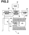
- Figure 2 is a block diagram of a part of the stencil printer shown in Figure 1,
- Figures 3A and 3B are views showing stencil making energy changing tables which the thermal head control system shown in Figure 2 is provided with, and
- Figure 4 a block diagram of a part of a stencil printer employing a thermal head control system in accordance with another embodiment of the present invention.
-
- A stencil printer employing a thermal head control system in accordance with an embodiment of the present invention will be described with reference to the drawings, hereinbelow. Figure 1 is a view showing in brief the stencil printer.
- As shown in Figure 1, the stencil printer comprises a reading
portion 10 which reads out an image on an original, astencil making portion 20 which makes a stencil from stencil material on the basis of the image information read by the readingportion 10, aprinting portion 30 which prints on a printing paper by the use of the stencil M made by thestencil making portion 20, apaper supply portion 40 which supplies the printing paper to theprinting portion 30, apaper discharge portion 50 which discharges the printed printing paper from theprinting portion 30, and astencil discharge portion 60 which discharges the stencil M after use. - The image read-out
portion 10 is an image scanner and comprises animage line sensor 12 which reads out an image on an original conveyed in a sub-scanning direction, andoriginal feed rollers 14. - The
stencil making portion 20 comprises a stencilmaterial roll portion 21, astencil making unit 22 having a thermal head where plurality of heater elements are arranged in a row, stencilmaterial feed rollers material guide rollers stencil cutter 28. As shown in Figure 2, in the stencilmaterial roll portion 21, astencil material roll 21b comprising stencil material M wound around apaper core 21a is mounted on amaster holder 80 to be changeable. A storage means 70 which stores length data on a total length of thestencil material roll 21b before use and the residue of the stencil material M after use of thestencil material roll 21b is disposed in asupport member 21c mounted for rotation on one end portion of thepaper core 21a of thestencil material roll 21b. In the storage means 70, the kind data of the stencil material M of thestencil material roll 21b and the date data on the date of production of thestencil material roll 21b have been further stored. The kind data of the stencil material M comprises, for instance, the modulus of the stencil material M. The storage means 70 comprises amemory IC 71 forming a non-volatile memory (e.g., an EEPROM) which can hold data for a predetermined time without power supply, and acontact 73 is provided on the tip of aboard 72 on which thememory IC 71 is mounted. Further, as shown in Figure 2, aconnector 74 to be electrically connected to thecontact 73 of the first storage means 70 of thestencil material roll 21b is disposed in themaster holder 80. Theconnector 74 functions as a part of a residue calculating means 65 to be described later. - The
printing portion 30 comprises a cylindrical ink-transmittable printing drum 31 which is formed of a porous metal plate or a mesh structure, anink supply system 34 having asqueegee roller 32, and adoctor roller 33 which are disposed inside theprinting drum 31, and apress roller 35. The stencil is wound around outer periphery of theprinting drum 31. - The
paper supply portion 40 comprises a paper supply table 41 on which printing papers P are stacked, a pick-uproller 42 which takes out the printing papers P one by one from the paper supply table 41, and a pair of timingrollers 43 which send a printing paper P between theprinting drum 31 and thepress roller 35. - The
stencil discharge portion 60 comprises astencil discharge box 61 which is disposed on one side of theprinting portion 30 and in which the stencil peeled off theprinting drum 31 is placed, and a pair ofstencil discharge rollers 62 which peel the stencil off theprinting drum 31 after use and convey the stencil peeled off theprinting drum 31 into thestencil discharge box 61. - Further, as shown in Figure 2, the stencil printer of this embodiment is provided with the residue calculating means 65 which calculates the residue of the
stencil material roll 21b by cumulatively subtracting the length of the stencil from the total length of thestencil material roll 21b before use each time a stencil is made and a thermal head control means 66 which controls the heating energy to thethermal head 22 on the basis of the stencil material roll residue calculated by the residue calculating means 65. - In the thermal head control means 66, a pair of stencil making energy changing tables shown in Figures 3A and 3B are stored. According to the stencil making energy changing table, the heating energy to the
thermal head 22 can be obtained on the basis of the residue of the stencil material M in thestencil material roll 21b and the elapsed time from production of thestencil material roll 21b as can be understood from Figures 3A or 3B. In the stencil making energy changing table, "standard" means predetermined standard heating energy, and, for instance, "+2.5%" means heating energy larger than the "standard" by 2.5%. The thermal head control means 66 has a pair of stencil making energy changing tables shown in Figures 3A and 3B, and selects the stencil making energy changing table shown in Figure 3A or that shown in Figure 3B on the basis of the kind data of the stencil material M stored in the storage means 70 of thestencil material roll 21b. In this particular embodiment, the kind data of the stencil material M represents the modulus of the stencil material M. When the modulus of the stencil material M is larger than a predetermined threshold value, the stencil making energy changing table shown in Figure 3A is selected, whereas when the modulus of the stencil material M is not larger than the predetermined threshold value, the stencil making energy changing table shown in Figure 3B is selected. That is, since as the modulus of the stencil material M is larger, contact of the stencil material M to thethermal head 22 becomes closer, the tables shown in Figures 3A and 3B are set so that the heating energy is smaller as the modulus of the stencil material M is larger. Further, since the surface smoothness of the stencil material M more deteriorates as the elapsed time from production of the stencil material roll becomes longer, the tables shown in Figures 3A and 3B are set so that the heating energy is larger as the elapsed time is longer. - Though, in this embodiment, the stencil making energy changing tables shown in Figures 3A and 3B are stored in the thermal
head control system 66 of the stencil printer, the stencil making energy changing tables shown in Figures 3A and 3B may be stored in the storage means 70 of thestencil material roll 21b while the thermalhead control system 66 selects the stencil making energy changing table shown in Figure 3A or that shown in Figure 3B which are stored in the storage means 70 on the basis of the kind data of the stencil material M read out from the storage means 70 and reads out the selected stencil making energy changing table from the storage means 70. - Operation of the stencil printer of this embodiment will be described, hereinbelow.
- A
stencil material roll 21b is first installed on themaster holder 80 and the stencil material M is unrolled from thestencil material roll 21b in a length corresponding to one stencil. Then the stencil material M is perforated into a stencil by thethermal head 22 whose heater elements are selectively heated in thestencil making portion 20. The heating energy thethermal head 22 is obtained in the manner to be described later and the temperature of thethermal head 22 is controlled. - In response to installment of the
stencil material roll 21b on themaster holder 80, theconnector 74 on themaster holder 80 is electrically connected to thecontact 73 of the storage means 70 provided on thestencil material roll 21b, whereby the total length of thestencil material roll 21b before use which is stored in the first storage means 71 is read out by the residue calculating means 65 and is stored in amemory 66 provided in the residue calculating means 65. Data on a length corresponding to one stencil has been stored in thememory 66, and the residue calculating means 65 calculates the number of stencils which the stencil printer can further make by dividing the total length of thestencil material roll 21b by the length corresponding to one stencil and outputs the number to the thermal head control means 66. Further, the kind data of the stencil material M and the date data on the date of production stored in the storage means 70 of thestencil material roll 21b are also output to the thermal head control means 66. The thermal head control means 66 selects the stencil making energy changing table shown in Figure 3A or that shown in Figure 3B on the basis of the kind data of the stencil material M and calculates the elapsed time from production of thestencil material roll 21b on the basis of the date data on the date of production. In this particular embodiment, atimer 67 which indicates the current time is provided in the stencil printer, and the thermal head control means 66 calculates the elapsed time by subtracting the date data representing the date of production of the stencil material roll from the date data representing the present read out from thetimer 67. The thermal head control means 66 obtains the heating energy to thethermal head 22 on the basis of the number of the stencils input thereinto in the manner described above, and the elapsed time calculated in the manner described above referring to the stencil making energy changing table selected according to the kind data of the stencil material M, and controls the voltage applied to thethermal head 22 on the basis of the obtained heating energy to thethermal head 22, thereby controlling the heating action of each heater elements of thethermal head 22. - The stencil made by the
thermal head 22 whose heating action is controlled in the manner described above is cut by thestencil cutter 28 and is wound around theprinting drum 31. - Ink in a predetermined color is supplied inside the
printing drum 31 by theink supply system 34. As the printing drum is rotated in the counterclockwise direction as seen in Figure 1, a printing paper P is moved left to right as seen in Figure 1 by the timingrollers 43 to be supplied between theprinting drum 31 and thepress roller 35 at a predetermined timing in synchronization with the rotation of theprinting drum 31. The printing paper P is subsequently pressed by thepress roller 35 against the stencil on the outer peripheral surface of theprinting drum 31, whereby the printing paper P is printed with the ink in the predetermined color. - Together with the stencil making action and the printing action described above, the length of the stencil which has been stored in the
memory 66 is subtracted from the total length of thestencil material roll 21b before use which has been stored in thememory 66 in the residue calculating means 65 and the value obtained is stored again in thememory 66 as the residue of thestencil material roll 21b. The residue of thestencil material roll 21b stored in thememory 66 is stored in the storage means 70 by way of theconnector 74 and thecontact 73. When the stencil making action is to be performed next, the residue calculating means 65 reads out the residue of thestencil material roll 21b which has been stored in the storage means 70 to calculate the number of stencils which can be further made in the same manner as described above, and output the number to the thermal head control means 66. The thermal head control means 66 obtains the heating energy to thethermal head 22 on the basis of the number of the stencils input thereinto in the manner described above, and the elapsed time calculated in the manner described above referring to the stencil making energy changing table and controls the temperature of thethermal head 22 on the basis of the obtained heating energy to thethermal head 22 during the next stencil making. - By repeating the action described above, the temperature of the
thermal head 22 is controlled with heating energy according to the residue of the stencil material M in thestencil material roll 21b and the elapsed time from production of thestencil material roll 21b. - In the above-mentioned stencil printer, since the residue of the stencil material M in the
stencil material roll 21b is calculated and the heating energy to thethermal head 22 is controlled on the basis of the calculated residue, that is, the heating energy to thethermal head 22 is controlled to be larger by the amount corresponding to deterioration of the surface smoothness of the stencil material due to reduction in the residue, the heating energy to the thermal head can be controlled according to the surface condition of the stencil material without adding to the overall size of the system or the cost of the system. Accordingly, deterioration of the quality of the printed image due to fluctuation in perforations can be avoided. - Further, since the elapsed time from production of the stencil material roll is obtained and the heating energy to the thermal head is controlled on the basis of the obtained elapsed time, the heating energy to the thermal head can be controlled according to the surface condition of the stencil material also for the deterioration of the surface smoothness of the stencil material due to elapse of the time from production of the stencil material roll.
- Further, since the kind of the stencil material is obtained and the stencil making energy changing table is selected on the basis of the obtained kind, the stencil making is stabilized without affected by difference in contact of the stencil material to the thermal head due to difference in the kind of the stencil material.
- It is possible to add a temperature detecting means 68 to the embodiment described above as shown in Figure 4 so that the working environmental temperature of the thermal head is measured, the stencil making energy changing table according to the working environmental temperature is stored in the thermal head control system, and the heating energy to the thermal head is obtained on the basis of the kind, the residue, the elapsed time from production and the working environmental temperature of the stencil material in the
stencil material roll 21b. In this case, the stencil making energy changing table may be made so that the heating energy to the thermal head is larger than as the working environmental temperature lowers under the condition where the kind, the residue, and the elapsed time from production of the stencil material are the same. - The heating energy to the thermal head need not be obtained on the basis of all of the kind, the residue, the elapsed time from production and the working environmental temperature of the stencil material in the
stencil material roll 21b, other any conditions may be added so long as the residue or the elapsed time is included in the conditions.
Claims (18)
- A thermal head control method of controlling heating energy to a thermal head perforating stencil material unrolled from a stencil material roll characterized by the steps of
obtaining a residue of the stencil material in the stencil material roll, and
controlling the heating energy to the thermal head on the basis of the residue of the stencil material obtained. - A thermal head control method as defined in Claim 1 in which the kind of the stencil material is obtained and the heating energy to the thermal head is controlled on the basis of the kind of the stencil material obtained and the residue.
- A thermal head control method as defined in Claim 1 in which the elapsed time from the production of the stencil material roll is obtained and the heating energy to the thermal head is controlled on the basis of the elapsed time from the production of the stencil material roll obtained and the residue.
- A thermal head control method of controlling heating energy to a thermal head perforating stencil material unrolled from a stencil material roll characterized by the steps of
obtaining the elapsed time from the production of the stencil material roll, and
controlling the heating energy to the thermal head on the basis of the elapsed time. - A thermal head control method as defined in Claim 4 in which the kind of the stencil material is obtained and the heating energy to the thermal head is controlled on the basis of the kind of the stencil material obtained and the elapsed time.
- A thermal head control system for controlling heating energy to a thermal head perforating stencil material unrolled from a stencil material roll characterized by
a residue obtaining means which obtains a residue of the stencil material in the stencil material roll, and
a thermal head controlling means which controls the heating energy to the thermal head on the basis of the residue obtained by the residue obtaining means. - A thermal head control system as defined in Claim 6 further comprising a temperature detecting means which detects the working environmental temperature of the thermal head wherein the thermal head controlling means controls the heating energy to the thermal head on the basis of the working environmental temperature of the thermal head detected by the temperature detecting means and the residue.
- A thermal head control system as defined in Claim 6 further comprising a kind obtaining means which obtains the kind of the stencil material wherein the thermal head controlling means controls the heating energy to the thermal head on the basis of the kind of the stencil material obtained by the kind obtaining means and the residue.
- A thermal head control system as defined in Claim 6 further comprising an elapsed time obtaining means which obtains the elapsed time from the production of the stencil material roll wherein the thermal head controlling means controls the heating energy to the thermal head on the basis of the elapsed time from the production of the stencil material roll obtained by the elapsed time obtaining means and the residue.
- A thermal head control system for controlling heating energy to a thermal head perforating stencil material unrolled from a stencil material roll characterized by
an elapsed time obtaining means which obtains the elapsed time from the production of the stencil material roll, and
a thermal head controlling means which controls the heating energy to the thermal head on the basis of the elapsed time obtained by the elapsed time obtaining means. - A thermal head control system as defined in Claim 10 further comprising a temperature detecting means which detects the working environmental temperature of the thermal head wherein the thermal head controlling means controls the heating energy to the thermal head on the basis of the working environmental temperature of the thermal head detected by the temperature detecting means and the elapsed time.
- A thermal head control system as defined in Claim 10 further comprising a kind obtaining means which obtains the kind of the stencil material and the thermal head controlling means controls the heating energy to the thermal head on the basis of the kind of the stencil material obtained by the kind obtaining means and the elapsed time.
- A thermal head control system as defined in any one of Claims 6 to 9 in which the stencil material roll is provided with a storage means which stores residue data according to the residue of the stencil material and the residue obtaining means may obtain the residue of the stencil material on the basis of the residue data read out from the storage means.
- A thermal head control system as defined in any one of Claims 9 to 12 in which the stencil material roll is provided with a storage means which stores date data on the date of production of the stencil material roll and
the elapsed time obtaining means obtains the elapsed time on the basis of the date data on the date of production of the stencil material roll read out from the storage means. - A thermal head control system as defined in any one of Claims 8 to 12 in which the stencil material roll is provided with a storage means which stores kind data according to the kind of the stencil material and
the kind obtaining means is a means for reading out the kind data from the storage means. - A stencil material roll used for carrying out the thermal head control method defined in any one of Claims 1 to 3 comprising a storage means which stores residue data according to the residue of the stencil material.
- A stencil material roll used for carrying out the thermal head control method defined in Claim 2 or 5 comprising a storage means which stores kind data according to the kind of the stencil material.
- A stencil material roll used for carrying out the thermal head control method defined in any one of Claims 3 to 5 comprising a storage means which stores date data on the date of production of the stencil material roll.
Applications Claiming Priority (3)
| Application Number | Priority Date | Filing Date | Title |
|---|---|---|---|
| JP2003004310 | 2003-01-10 | ||
| JP2003004310A JP4224306B2 (en) | 2003-01-10 | 2003-01-10 | Thermal head control method and apparatus |
| PCT/JP2003/015551 WO2004062914A1 (en) | 2003-01-10 | 2003-12-04 | Method and system for controlling thermal head and stencil paper roll |
Publications (3)
| Publication Number | Publication Date |
|---|---|
| EP1582345A1 true EP1582345A1 (en) | 2005-10-05 |
| EP1582345A4 EP1582345A4 (en) | 2006-06-07 |
| EP1582345B1 EP1582345B1 (en) | 2009-04-29 |
Family
ID=32708947
Family Applications (1)
| Application Number | Title | Priority Date | Filing Date |
|---|---|---|---|
| EP03780681A Expired - Lifetime EP1582345B1 (en) | 2003-01-10 | 2003-12-04 | Method and system for controlling thermal head |
Country Status (6)
| Country | Link |
|---|---|
| US (3) | US7523702B2 (en) |
| EP (1) | EP1582345B1 (en) |
| JP (1) | JP4224306B2 (en) |
| CN (2) | CN1735513B (en) |
| DE (1) | DE60327470D1 (en) |
| WO (1) | WO2004062914A1 (en) |
Families Citing this family (7)
| Publication number | Priority date | Publication date | Assignee | Title |
|---|---|---|---|---|
| JP4224306B2 (en) * | 2003-01-10 | 2009-02-12 | 理想科学工業株式会社 | Thermal head control method and apparatus |
| JP3808834B2 (en) | 2003-02-17 | 2006-08-16 | 理想科学工業株式会社 | Image forming method and apparatus |
| US20060099412A1 (en) * | 2004-11-05 | 2006-05-11 | Ross Peggy S | Masking tape with stencil and method of use |
| JP4727213B2 (en) * | 2004-11-22 | 2011-07-20 | 東北リコー株式会社 | Thermal stencil printing machine |
| JP4652128B2 (en) * | 2005-05-26 | 2011-03-16 | 東北リコー株式会社 | Printing device |
| JP2008290339A (en) * | 2007-05-24 | 2008-12-04 | Tohoku Ricoh Co Ltd | Plate making apparatus, printing apparatus and molten paint adhesion preventing method |
| JP5066717B2 (en) * | 2007-11-15 | 2012-11-07 | 東北リコー株式会社 | Plate making apparatus and stencil printing apparatus |
Family Cites Families (12)
| Publication number | Priority date | Publication date | Assignee | Title |
|---|---|---|---|---|
| JPH10329401A (en) * | 1997-05-30 | 1998-12-15 | Tohoku Ricoh Co Ltd | Stencil printer and processing device thereof |
| JP3253279B2 (en) * | 1998-09-01 | 2002-02-04 | 理想科学工業株式会社 | Heat-sensitive stencil paper |
| JP4106156B2 (en) | 1999-07-07 | 2008-06-25 | 理想科学工業株式会社 | Stencil printing machine |
| JP3656891B2 (en) * | 1999-08-31 | 2005-06-08 | 理想科学工業株式会社 | Thermal head |
| JP2001260406A (en) * | 2000-03-16 | 2001-09-25 | Fuji Photo Film Co Ltd | Method of correcting sensitivity or density of printer and thermal printer |
| JP2001287333A (en) | 2000-04-07 | 2001-10-16 | Tohoku Ricoh Co Ltd | Thermal plate making device and thermal plate making printing device |
| JP2001315461A (en) * | 2000-05-09 | 2001-11-13 | Toray Ind Inc | Thermal stencil master |
| JP2002007946A (en) | 2000-06-26 | 2002-01-11 | Nec Corp | Price settlement system and settlement method therefor |
| JP3958535B2 (en) * | 2000-07-03 | 2007-08-15 | 理想科学工業株式会社 | Plate making method and apparatus |
| US6786146B2 (en) | 2000-11-08 | 2004-09-07 | Tohoku Ricoh Co., Ltd. | Stencil printer |
| JP2002144689A (en) * | 2000-11-09 | 2002-05-22 | Tohoku Ricoh Co Ltd | Stencil printing machine |
| JP4224306B2 (en) * | 2003-01-10 | 2009-02-12 | 理想科学工業株式会社 | Thermal head control method and apparatus |
-
2003
- 2003-01-10 JP JP2003004310A patent/JP4224306B2/en not_active Expired - Lifetime
- 2003-12-04 DE DE60327470T patent/DE60327470D1/en not_active Expired - Lifetime
- 2003-12-04 WO PCT/JP2003/015551 patent/WO2004062914A1/en not_active Ceased
- 2003-12-04 CN CN2003801085806A patent/CN1735513B/en not_active Expired - Lifetime
- 2003-12-04 EP EP03780681A patent/EP1582345B1/en not_active Expired - Lifetime
- 2003-12-04 CN CNA2007101270258A patent/CN101085564A/en active Pending
- 2003-12-04 US US10/541,718 patent/US7523702B2/en not_active Expired - Fee Related
-
2008
- 2008-07-16 US US12/218,592 patent/US20080278562A1/en not_active Abandoned
- 2008-07-16 US US12/218,539 patent/US20080278563A1/en not_active Abandoned
Non-Patent Citations (2)
| Title |
|---|
| No further relevant documents disclosed * |
| See also references of WO2004062914A1 * |
Also Published As
| Publication number | Publication date |
|---|---|
| JP4224306B2 (en) | 2009-02-12 |
| EP1582345B1 (en) | 2009-04-29 |
| DE60327470D1 (en) | 2009-06-10 |
| JP2004216624A (en) | 2004-08-05 |
| US20060107851A1 (en) | 2006-05-25 |
| CN1735513A (en) | 2006-02-15 |
| US20080278563A1 (en) | 2008-11-13 |
| US7523702B2 (en) | 2009-04-28 |
| CN1735513B (en) | 2010-04-28 |
| EP1582345A4 (en) | 2006-06-07 |
| WO2004062914A1 (en) | 2004-07-29 |
| US20080278562A1 (en) | 2008-11-13 |
| CN101085564A (en) | 2007-12-12 |
Similar Documents
| Publication | Publication Date | Title |
|---|---|---|
| US20080278563A1 (en) | Method of and system for controlling thermal head and stencil material roll | |
| US7441498B2 (en) | Image forming system | |
| EP1595711B1 (en) | Image formation method, device, and consumables | |
| EP1584481A1 (en) | Method and system for carrying stencil paper and stencil paper roll | |
| US20080168911A1 (en) | Method of and system for stencil printing and ink container and stencil material roll | |
| US20060096474A1 (en) | Method of calculating stencil material roll residue, stencil making system and stencil material roll | |
| JP5304067B2 (en) | Thermal stencil printing machine | |
| JP4430345B2 (en) | Plate making apparatus and plate making printing apparatus | |
| WO2005072969A1 (en) | Stencil printing machine and ink container | |
| JP2004299156A (en) | Image forming device | |
| JP2010083119A (en) | Image forming apparatus and stencil printing device | |
| JP2008302703A (en) | Image forming apparatus | |
| JP2002001896A (en) | Plate making apparatus and plate making and printing apparatus | |
| JP2010012689A (en) | Thermosensitive stencil printing apparatus | |
| JP2004155048A (en) | Thermal head, method for selecting thermal head and apparatus for stencil printing | |
| JP2006142686A (en) | Thermal stencil printing equipment |
Legal Events
| Date | Code | Title | Description |
|---|---|---|---|
| PUAI | Public reference made under article 153(3) epc to a published international application that has entered the european phase |
Free format text: ORIGINAL CODE: 0009012 |
|
| 17P | Request for examination filed |
Effective date: 20050705 |
|
| AK | Designated contracting states |
Kind code of ref document: A1 Designated state(s): AT BE BG CH CY CZ DE DK EE ES FI FR GB GR HU IE IT LI LU MC NL PT RO SE SI SK TR |
|
| RBV | Designated contracting states (corrected) |
Designated state(s): DE FR GB |
|
| A4 | Supplementary search report drawn up and despatched |
Effective date: 20060503 |
|
| RIC1 | Information provided on ipc code assigned before grant |
Ipc: B41C 1/14 20060101ALI20060426BHEP Ipc: B41C 1/055 20060101AFI20040803BHEP Ipc: B41N 1/24 20060101ALI20060426BHEP Ipc: B41L 13/04 20060101ALI20060426BHEP |
|
| 17Q | First examination report despatched |
Effective date: 20060830 |
|
| RTI1 | Title (correction) |
Free format text: METHOD AND SYSTEM FOR CONTROLLING THERMAL HEAD |
|
| GRAP | Despatch of communication of intention to grant a patent |
Free format text: ORIGINAL CODE: EPIDOSNIGR1 |
|
| GRAS | Grant fee paid |
Free format text: ORIGINAL CODE: EPIDOSNIGR3 |
|
| GRAA | (expected) grant |
Free format text: ORIGINAL CODE: 0009210 |
|
| AK | Designated contracting states |
Kind code of ref document: B1 Designated state(s): DE FR GB |
|
| REG | Reference to a national code |
Ref country code: GB Ref legal event code: FG4D |
|
| REF | Corresponds to: |
Ref document number: 60327470 Country of ref document: DE Date of ref document: 20090610 Kind code of ref document: P |
|
| PLBE | No opposition filed within time limit |
Free format text: ORIGINAL CODE: 0009261 |
|
| STAA | Information on the status of an ep patent application or granted ep patent |
Free format text: STATUS: NO OPPOSITION FILED WITHIN TIME LIMIT |
|
| 26N | No opposition filed |
Effective date: 20100201 |
|
| REG | Reference to a national code |
Ref country code: FR Ref legal event code: PLFP Year of fee payment: 13 |
|
| REG | Reference to a national code |
Ref country code: FR Ref legal event code: PLFP Year of fee payment: 14 |
|
| REG | Reference to a national code |
Ref country code: DE Ref legal event code: R082 Ref document number: 60327470 Country of ref document: DE Representative=s name: KLUNKER IP PATENTANWAELTE PARTG MBB, DE |
|
| REG | Reference to a national code |
Ref country code: FR Ref legal event code: PLFP Year of fee payment: 15 |
|
| PGFP | Annual fee paid to national office [announced via postgrant information from national office to epo] |
Ref country code: DE Payment date: 20191119 Year of fee payment: 17 |
|
| PGFP | Annual fee paid to national office [announced via postgrant information from national office to epo] |
Ref country code: FR Payment date: 20191115 Year of fee payment: 17 |
|
| PGFP | Annual fee paid to national office [announced via postgrant information from national office to epo] |
Ref country code: GB Payment date: 20191206 Year of fee payment: 17 |
|
| REG | Reference to a national code |
Ref country code: DE Ref legal event code: R119 Ref document number: 60327470 Country of ref document: DE |
|
| GBPC | Gb: european patent ceased through non-payment of renewal fee |
Effective date: 20201204 |
|
| PG25 | Lapsed in a contracting state [announced via postgrant information from national office to epo] |
Ref country code: FR Free format text: LAPSE BECAUSE OF NON-PAYMENT OF DUE FEES Effective date: 20201231 |
|
| PG25 | Lapsed in a contracting state [announced via postgrant information from national office to epo] |
Ref country code: DE Free format text: LAPSE BECAUSE OF NON-PAYMENT OF DUE FEES Effective date: 20210701 Ref country code: GB Free format text: LAPSE BECAUSE OF NON-PAYMENT OF DUE FEES Effective date: 20201204 |