EP1582153A1 - Embolus forming in-vivo indwelling coil - Google Patents
Embolus forming in-vivo indwelling coil Download PDFInfo
- Publication number
- EP1582153A1 EP1582153A1 EP04701687A EP04701687A EP1582153A1 EP 1582153 A1 EP1582153 A1 EP 1582153A1 EP 04701687 A EP04701687 A EP 04701687A EP 04701687 A EP04701687 A EP 04701687A EP 1582153 A1 EP1582153 A1 EP 1582153A1
- Authority
- EP
- European Patent Office
- Prior art keywords
- coil
- main body
- suppressing member
- vivo indwelling
- stretch
- Prior art date
- Legal status (The legal status is an assumption and is not a legal conclusion. Google has not performed a legal analysis and makes no representation as to the accuracy of the status listed.)
- Granted
Links
Images

Classifications
-
- A—HUMAN NECESSITIES
- A61—MEDICAL OR VETERINARY SCIENCE; HYGIENE
- A61N—ELECTROTHERAPY; MAGNETOTHERAPY; RADIATION THERAPY; ULTRASOUND THERAPY
- A61N2/00—Magnetotherapy
- A61N2/06—Magnetotherapy using magnetic fields produced by permanent magnets
-
- A—HUMAN NECESSITIES
- A61—MEDICAL OR VETERINARY SCIENCE; HYGIENE
- A61B—DIAGNOSIS; SURGERY; IDENTIFICATION
- A61B17/00—Surgical instruments, devices or methods
- A61B17/12—Surgical instruments, devices or methods for ligaturing or otherwise compressing tubular parts of the body, e.g. blood vessels or umbilical cord
- A61B17/12022—Occluding by internal devices, e.g. balloons or releasable wires
- A61B17/12131—Occluding by internal devices, e.g. balloons or releasable wires characterised by the type of occluding device
- A61B17/12181—Occluding by internal devices, e.g. balloons or releasable wires characterised by the type of occluding device formed by fluidized, gelatinous or cellular remodelable materials, e.g. embolic liquids, foams or extracellular matrices
- A61B17/1219—Occluding by internal devices, e.g. balloons or releasable wires characterised by the type of occluding device formed by fluidized, gelatinous or cellular remodelable materials, e.g. embolic liquids, foams or extracellular matrices expandable in contact with liquids
-
- A—HUMAN NECESSITIES
- A61—MEDICAL OR VETERINARY SCIENCE; HYGIENE
- A61B—DIAGNOSIS; SURGERY; IDENTIFICATION
- A61B17/00—Surgical instruments, devices or methods
- A61B17/12—Surgical instruments, devices or methods for ligaturing or otherwise compressing tubular parts of the body, e.g. blood vessels or umbilical cord
- A61B17/12022—Occluding by internal devices, e.g. balloons or releasable wires
-
- A—HUMAN NECESSITIES
- A61—MEDICAL OR VETERINARY SCIENCE; HYGIENE
- A61B—DIAGNOSIS; SURGERY; IDENTIFICATION
- A61B17/00—Surgical instruments, devices or methods
- A61B17/12—Surgical instruments, devices or methods for ligaturing or otherwise compressing tubular parts of the body, e.g. blood vessels or umbilical cord
- A61B17/12022—Occluding by internal devices, e.g. balloons or releasable wires
- A61B17/12131—Occluding by internal devices, e.g. balloons or releasable wires characterised by the type of occluding device
- A61B17/1214—Coils or wires
- A61B17/12145—Coils or wires having a pre-set deployed three-dimensional shape
-
- A—HUMAN NECESSITIES
- A61—MEDICAL OR VETERINARY SCIENCE; HYGIENE
- A61B—DIAGNOSIS; SURGERY; IDENTIFICATION
- A61B17/00—Surgical instruments, devices or methods
- A61B17/12—Surgical instruments, devices or methods for ligaturing or otherwise compressing tubular parts of the body, e.g. blood vessels or umbilical cord
- A61B17/12022—Occluding by internal devices, e.g. balloons or releasable wires
- A61B17/12131—Occluding by internal devices, e.g. balloons or releasable wires characterised by the type of occluding device
- A61B17/1214—Coils or wires
- A61B17/12154—Coils or wires having stretch limiting means
-
- A—HUMAN NECESSITIES
- A61—MEDICAL OR VETERINARY SCIENCE; HYGIENE
- A61N—ELECTROTHERAPY; MAGNETOTHERAPY; RADIATION THERAPY; ULTRASOUND THERAPY
- A61N2/00—Magnetotherapy
- A61N2/02—Magnetotherapy using magnetic fields produced by coils, including single turn loops or electromagnets
-
- A—HUMAN NECESSITIES
- A61—MEDICAL OR VETERINARY SCIENCE; HYGIENE
- A61B—DIAGNOSIS; SURGERY; IDENTIFICATION
- A61B17/00—Surgical instruments, devices or methods
- A61B2017/00004—(bio)absorbable, (bio)resorbable or resorptive
Definitions
- the present invention relates to an embolus forming in-vivo indwelling coil, and particularly to an embolus forming in-vivo indwelling coil used for, for example, changing or interrupting a blood flow or embolizing a lesion.
- a currently known treatment with less invasive for an aneurysm or the like is vascular embolization in which an embolus forming in-vivo indwelling device is indwelled in an aneurysm.
- the embolus forming in-vivo indwelling device indwelled in the aneurysm physically interferes with a blood flow and forms a thrombus around the embolus forming in-vivo indwelling device, thereby decreasing a danger of rupture of the aneurysm.
- embolus forming in-vivo indwelling device which is indwelled at a predetermined position in a blood vessel, such as an aneurysm, is an embolus forming in-vivo indwelling device comprising a metal coil (referred to as an "embolus forming coil” hereinafter).
- the embolus forming coil is introduced into an aneurysm through an appropriate catheter using pushing means (inductor) detachably connected to an end of the coil. Then, the embolus forming coil is separated and indwelled at the predetermined position.
- an embolus forming coil is required to have various characteristics: (1) In order to securely introduce and indwell the coil at the predetermined position without damaging a blood vessel, the coil has high flexibility for permitting the coil to be deformed along the shape of a blood vessel. (2) The coil has the function to prevent or suppress unrestricted stretch so as to permit a secured re-indwelling operation for recovering the coil and correcting the indwelling position after the coil has been pushed out from the catheter and placed in a blood vessel. Namely, for example, when the embolus forming coil gets caught on the tip end of the catheter and extended thereby, the embolus forming coil cannot be easily recovered or the indwelling position may be damaged. Therefore, the embolus forming coil must be formed so as not to cause this problem.
- the present invention has been achieved on the basis of the above-described situation, and an object of the present invention is to provide an embolus forming in-vivo indwelling coil which has so high flexibility that the coil can be securely introduced and indwelled at a predetermined position in the body, and which permits a secured re-indwelling operation including recovery of the in-vivo indwelling device, for example, for recovering the disposed device and correcting the position, and thus has high safety and high operationality.
- An embolus forming in-vivo indwelling coil of the present invention comprises a coil main body having flexibility and an stretch suppressing member which is provided on one or both of the inner and outer peripheries of the coil main body and which is made of a water-swellable polymer material for suppressing stretch of the coil main body by swelling with absorbed water.
- the water-swellable polymer material constituting the stretch suppressing member preferably comprises a polyvinyl alcohol polymer.
- the wire constituting the coil main body has a diameter of 10 to 120 ⁇ m, and the coil main body has a coil diameter of 100 to 500 ⁇ m, a coil length of 2 to 500 mm, and a number of turns of 1 to 100 per unit length (1 mm).
- the rod-like or cylindrical stretch suppressing member is provided in the coil main body so as to pass through the coil main body and extend in the coil axial direction of the coil main body.
- the diameter of the stretch suppressing member is preferably smaller than the inner diameter of the coil main body by about 1 to 50% in a dry state.
- the cylindrical or tubular stretch suppressing member may be provided to cover the entire region of the outer periphery of the coil main body in the coil axial direction.
- the thickness of the stretch suppressing member is preferably 0.01 to 0.10 mm, and the clearance between the outer periphery of the coil main body and the inner periphery of the stretch suppressing member is preferably 0 to 100 ⁇ m.
- the embolus forming in-vivo indwelling coil of the present invention may comprise a rod-like or cylindrical stretch suppressing member provided so as to extend in the coil axial direction of a coil main body and pass through the coil main body, and a cylindrical or tubular stretch suppressing member provided to cover the entire region of the outer periphery of the coil main body in the coil axial direction.
- the embolus forming in-vivo indwelling coil of the present invention is used in a swollen state in which the stretch suppressing member is previously swollen.
- the stretch suppressing member enters the coil pitches (wire spaces) in the inner periphery or the outer periphery of the coil main body to create a state in which the adjacent wire turns are substantially connected to each other.
- the stretch suppressing member has deformability, and thus, basically, the flexibility of the coil main body is not significantly inhibited by the stretch suppressing member. Therefore, the embolus forming in-vivo indwelling coil can be formed with high flexibility, and high operationality can be obtained in the indwelling operation. As a result, the embolus forming in-vivo indwelling coil can be securely introduced and indwelled at a predetermined position through an appropriate catheter.
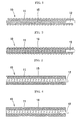
- Fig. 1 is a sectional view schematically illustrating the configuration of an example of an embolus forming in-vivo indwelling coil of the present invention.
- the embolus forming in-vivo indwelling coil (simply referred to as an "in-vivo indwelling coil” hereinafter) 10 comprises a coil main body 11 having flexibility.
- a rod-shaped coil separating member 12 for holding the coil main body 11 is provided at the proximal end (the right-side end in Fig. 1) of the coil main body 11 so as to be partially fixed on the inner periphery of the coil main body 11 at the proximal end to project outward (rightward in Fig. 1) from the proximal end of the coil main body 11 in the coil axial direction.
- any one of various materials for example, a metal wire, a resin wire, and the like, can be used as long as the wire does not adversely affect a human body (having biocompatibility) when being indwelled in the human body for a long time.
- Examples of the metal wire for forming the coil main body 11 include tungsten, gold, platinum, and stainless steel, and alloys thereof.
- polyester resins such as polyethylene terephthalate (PET), polyolefin resins such as polypropylene (PP), and polyamide resins such as nylon.
- the coil main body 11 constituting the in-vivo indwelling coil 10 has flexibility and preferably has the structure below depending upon the material of the wire used for forming the coil main body 11.
- the diameter (element wire diameter) of the wire constituting the coil main body 11 is 10 to 120 ⁇ m, and the coil main body 11 has a coil diameter of 100 to 500 ⁇ m, a coil length of 2 to 500 mm, and a number of turns of 1 to 100 per unit length (1 mm).
- the in-vivo indwelling coil 10 further comprises an stretch suppressing member 15 of, for example, a rod shape, which is made of a water-swellable polymer material and functions to suppress stretch of the coil main body 11 by swelling with absorbed water, and which is provided to extend in the coil axial direction of the coil main body 11 and to pass through the coil main body 11 (through a lumen).
- an stretch suppressing member 15 of, for example, a rod shape, which is made of a water-swellable polymer material and functions to suppress stretch of the coil main body 11 by swelling with absorbed water, and which is provided to extend in the coil axial direction of the coil main body 11 and to pass through the coil main body 11 (through a lumen).
- any material which has proper water-swellability and no adverse effect on human bodies can be used.
- the polymer material include polyvinyl alcohol polymers; natural polysaccharides such as carrageenan, agar, alginic acid, starch, pectin, galactomannan, xanthane, hyaluronic acid, chitin, and chitosan; natural proteins such as collagen, actin, myosin, tublin, casein, and fibrin; chemically-modified natural polymers such as carboxymethylated cellulose, carboxymethylated starch, acrylic acid-grafted starch, acrylonitrile-grafted cellulose hydrolyzates; and synthetic polymers such as polyacrylic acid, polyvinyl alcohol, polyethyleneimine, polyhydroxyethyl methacrylate, polyvinylpyrrolidone, and polyethylene oxide.
- polyvinyl alcohol polymers are preferred because a crystalline substance can be
- the diameter of the stretch suppressing member 15 depends on the water-swellability of the material of the stretch suppressing member 15, but the diameter may be determined so that in a dry state, it can be inserted into the coil main body (lumen).
- the diameter is preferably smaller than the coil diameter of the coil main body 11 by about 1 to 50%.
- the stretch suppressing member 15 is preferably disposed to extend over the entire region of the coil main body 11 in the coil axial direction.
- the stretch suppressing member 15 preferably has a length which is the same as or larger than the coil length of the coil main body 11.
- the cylindrical or tubular stretch suppressing member 15 may be provided to cover the entire region of the outer periphery of the coil main body 11 in the coil axial direction.
- the thickness of the stretch suppressing member 15, which constitutes the in-vivo indwelling coil 10, can be properly determined to express the intended stretch preventing effect in a swollen state.
- the diameter is preferably 0.01 to 0.10 mm
- the clearance between the outer periphery of the coil main body 11 and the inner periphery of the stretch suppressing member 15 is preferably 0 to 100 ⁇ m.
- the above-described in-vivo indwelling coil 10 can be also used in a state in which the linear primary form is maintained.
- the coil 10 is preferably used, for example, in a state in which the linear coil main body 11 is helically coiled to form a secondary coil or in a state in which the coil main body 11 is formed in a S- or J-like three-dimensional shape, or another secondary shape.
- the method for using the in-vivo indwelling coil 10 will be described below with reference to an example in which the coil 10 is applied to treatment of an aneurysm.
- the stretch suppressing member 15 constituting the in-vivo indwelling coil 10 is swollen by, for example, immersing in appropriate swelling water.
- the swelling water is not particularly limited as long as it is not harmful to organisms.
- physiological saline purified water, extra-pure water, ion-exchanged water, an aqueous solution of a compound such as dimethylsulfoxide, blood, or the like can be used.
- the time of immersion of the in-vivo indwelling coil 10 in the swelling water is preferably, for example, 5 to 180 seconds depending on the constitutive material and configuration of the stretch suppressing member 15, and the like.
- the stretch suppressing member 15 of the in-vivo indwelling coil 10 When the stretch suppressing member 15 of the in-vivo indwelling coil 10 is swollen, the stretch suppressing member 15 enters the coil pitches (wire spaces) in the inner periphery of the coil main body 11 as shown in Fig. 2, or the stretch suppressing member 15 enters the coil pitches in the outer periphery of the coil main body 11 as shown in Fig. 4. Namely, the adjacent turns of the wire, which constitutes the coil main body 11, are substantially connected to each other. In this state, the indwelling coil 10 is formed in a secondary shape, for example, a secondary coil, and then detachably mounted on the tip of a guide wire.
- a secondary shape for example, a secondary coil
- Examples of a method for separating the in-vivo indwelling coil 10 from the guide wire include a mechanical separating method (1) in which the coil separating member 12 of the in-vivo indwelling coil 10 is mechanically engaged with the guide wire, and an electric separating method (2) in which for example, a monopolar high-frequency current is supplied to melt and disconnect the coil separating member 12 of the in-vivo indwelling coil 10 by heating with the high-frequency current, thereby separating the in-vivo indwelling coil 10 from the guide wire.
- a proper catheter is endermically inserted into a blood vessel using a puncture needle until the end of the catheter reaches the inlet of an aneurysm.
- the in-vivo indwelling coil 10 is linearly stretched and returned to the primary form (shown in Fig. 2 or 4).
- the guide wire is inserted into the catheter and moved forward to push out the in-vivo indwelling coil 10 from the end of the catheter and dispose the in-vivo indwelling coil 10 in the aneurysm.
- the in-vivo indwelling coil 10 When the in-vivo indwelling coil 10 is push out from the catheter, it is restored to the secondary coil, which is a secondary form, in which the in-vivo indwelling coil 10 is three-dimensionally tangled. In this state, the complete insertion of the in-vivo indwelling coil 10 into the aneurysm is confirmed by radioscopy. Then, the in-vivo indwelling coil 10 is separated from the end of the guide wire and indwelled in the aneurysm.
- the above-described indwelling operation is repeated using a plurality of the in-vivo indwelling coils 10 to fill the aneurysm with a plurality of in-vivo indwelling coils 10 and form a thrombus, thereby inhibiting a blood inflow to the aneurysm.
- rupture of the aneurysm can be securely prevented.
- the in-vivo indwelling coil 10 of the present invention is used after the stretch suppressing member 15 is previously swollen.
- the stretch suppressing member 15 enters the wire spaces in the inner periphery or the outer periphery of the coil main body 11 to create a state in which the adjacent wire turns are substantially connected to each other.
- the stretch suppressing member 15 is swollen to fill in the coil main body 11 (lumen) and enters the coil pitches in the inner periphery of the coil main body 11, as shown in Fig. 2.
- the stretch suppressing member 15 is swollen to enter the coil pitches from the outer periphery of the coil main body 11, thereby causing a state in which the adjacent wire turns are substantially connected to each other. As a result, the coil main body 11 is supported by the stretch suppressing member 15.
- the stretch suppressing member 15 is formed with deformability in a swollen state, and thus, basically, the flexibility of the coil main body 11 is not significantly inhibited by the stretch suppressing member 15. Therefore, the in-vivo indwelling coil 10 can be formed with high flexibility, and high operationality of the indwelling operation can be achieved. Consequently, the in-vivo indwelling coil 10 can be securely introduced and indwelled at the predetermined position through the appropriate catheter.
- the in-vivo indwelling coil 10 of the present invention is returned into the catheter in the state in which stretch of the coil main body in the coil axial direction is restricted because the adjacent turns of the wire constituting the coil main body 11 are substantially connected to each other by the stretch suppressing member 15. Therefore, the re-indwelling operation including recovery of the in-vivo indwelling coil 10 can be securely performed. As a result, the in-vivo indwelling coil 10 can be formed with high safety.
- the stretch suppressing member 15 is provided over the entire region of the outer periphery of the coil main body 11, and the stretch suppressing member 15 is made of a flexible material having deformability in a swollen state. Therefore, the lubricating effect is exhibited in moving the in-vivo indwelling coil 10 inserted in the catheter to the predetermined position, thereby achieving high operationality. Also, since the coil main body 11 is not exposed, damage to the applied position can be securely prevented to achieve the function to protect the applied position.
- a rod-shaped stretch suppressing member comprising polyvinyl alcohol and having a diameter of 120 ⁇ m and a length of 50 mm was inserted into a metal coil (coil diameter: 250 ⁇ m, coil length: 50 mm, number of turns per 1 mm: 20) which was formed by coiling a tungsten wire having an element wire diameter of 50 ⁇ m.
- a metal coil coil diameter: 250 ⁇ m, coil length: 50 mm, number of turns per 1 mm: 20
- a metal coil having the same structure as in Production Example 1 was formed, and a cylindrical stretch suppressing member comprising polyvinyl alcohol and having a diameter of 350 ⁇ m, a thickness of 50 ⁇ m, and a length of 50 mm was disposed to cover the entire region of the outer periphery of the metal coil to produce an in-vivo indwelling coil having the structure shown in Fig. 3. This is referred to as "indwelling coil 2".
- a metal coil having the same structure as in Production Example 1 was formed, and a rod-shaped stretch suppressing member comprising polyvinyl alcohol and having a diameter of 120 ⁇ m and a length of 50 mm was inserted into the metal coil. Furthermore, a cylindrical stretch suppressing member comprising polyvinyl alcohol and having a diameter of 350 ⁇ m, a thickness of 50 ⁇ m, and a length of 50 mm was disposed to cover the entire region of the outer periphery of the metal coil was disposed to cover the entire region of the outer periphery of the metal coil to produce an in-vivo indwelling coil. This is referred to as "indwelling coil 3".
- an embolus forming in-vivo indwelling coil of the present invention is used in a state in which an stretch suppressing member is previously swollen.
- the stretch suppressing member enters the coil pitches (wire spaces) in the inner periphery or the outer periphery of the coil main body to create a state in which the adjacent wire turns are substantially connected to each other.
- the stretch suppressing member has deformability, and thus, basically, the flexibility of the coil main body is not significantly inhibited by the stretch suppressing member. Therefore, the embolus forming in-vivo indwelling coil can be formed with high flexibility, and high operationality can be obtained in the indwelling operation. As a result, the embolus forming in-vivo indwelling coil can be securely introduced and indwelled at a predetermined position through an appropriate catheter.
Landscapes
- Health & Medical Sciences (AREA)
- Life Sciences & Earth Sciences (AREA)
- Surgery (AREA)
- General Health & Medical Sciences (AREA)
- Public Health (AREA)
- Veterinary Medicine (AREA)
- Engineering & Computer Science (AREA)
- Biomedical Technology (AREA)
- Nuclear Medicine, Radiotherapy & Molecular Imaging (AREA)
- Animal Behavior & Ethology (AREA)
- Molecular Biology (AREA)
- Medical Informatics (AREA)
- Reproductive Health (AREA)
- Heart & Thoracic Surgery (AREA)
- Vascular Medicine (AREA)
- Radiology & Medical Imaging (AREA)
- Surgical Instruments (AREA)
Abstract
Description
in which stretch of the coil main body in the coil axial direction is restricted because the adjacent turns of the wire constituting the coil
| Swelling conditions | ||||
| Swelling water | Rate of volume increase (%) | Flexibility of whole indwelling coil (mN/mm2) | Elongation of coil main body (mm) | |
| Indwelling coil 1 | Purified water | 185 | 8 | 3 |
| Indwelling coil 2 | Physiological saline | 115 | 8 | 3 |
| Indwelling coil 3 | Purified water | 123 | 10 | 2 |
Claims (8)
- An embolus forming in-vivo indwelling coil comprising a coil main body having flexibility and an stretch suppressing member which is provided on one or both of the inner and outer peripheries of the coil main body and which is made of a water-swellable polymer material for suppressing stretch of the coil main body by swelling with absorbed water.
- The embolus forming in-vivo indwelling coil according to claim 1, wherein the water-swellable polymer material constituting the stretch suppressing member comprises a polyvinyl alcohol polymer.
- The embolus forming in-vivo indwelling coil according to claim 1 or 2, wherein the wire constituting the coil main body has a diameter of 10 to 120 µm, and the coil main body has a coil diameter of 100 to 500 µm, a coil length of 2 to 500 mm, and a number of turns of 1 to 100 per unit length (1 mm).
- The embolus forming in-vivo indwelling coil according to any one of claims 1 to 3, wherein the stretch suppressing member has a rod-like shape or cylindrical shape and is provided in the coil main body so as to pass through the coil main body and extend in the coil axial direction of the coil main body.
- The embolus forming in-vivo indwelling coil according to claim 4, wherein the diameter of the stretch suppressing member is smaller than the inner diameter of the coil main body by about 1 to 50% in a dry state.
- The embolus forming in-vivo indwelling coil according to any one of claims 1 to 3, wherein the stretch suppressing member has a cylindrical or tubular shape and is provided to cover the entire region of the outer periphery of the coil main body in the coil axial direction.
- The embolus forming in-vivo indwelling coil according to claim 6, wherein, in a dry state, the thickness of the stretch suppressing member is 0.01 to 0.10 mm, and the clearance between the outer periphery of the coil main body and the inner periphery of the stretch suppressing member is 0 to 100 µm.
- The embolus forming in-vivo indwelling coil according to any one of claims 1 to 3, wherein a stretch suppressing member has a rod-like or cylindrical shape and is provided so as to extend in the coil axial direction of a coil main body and pass through the coil main body, and another stretch suppressing member has a cylindrical or tubular shape and is provided to cover the entire region of the outer periphery of the coil main body in the coil axial direction.
Applications Claiming Priority (3)
| Application Number | Priority Date | Filing Date | Title |
|---|---|---|---|
| JP2003005158 | 2003-01-10 | ||
| JP2003005158 | 2003-01-10 | ||
| PCT/JP2004/000137 WO2004062510A1 (en) | 2003-01-10 | 2004-01-13 | Embolus forming in-vivo indwelling coil |
Publications (3)
| Publication Number | Publication Date |
|---|---|
| EP1582153A1 true EP1582153A1 (en) | 2005-10-05 |
| EP1582153A4 EP1582153A4 (en) | 2011-07-20 |
| EP1582153B1 EP1582153B1 (en) | 2013-05-22 |
Family
ID=32709005
Family Applications (1)
| Application Number | Title | Priority Date | Filing Date |
|---|---|---|---|
| EP04701687.8A Expired - Lifetime EP1582153B1 (en) | 2003-01-10 | 2004-01-13 | Embolus forming in-vivo indwelling coil |
Country Status (7)
| Country | Link |
|---|---|
| US (1) | US20060217758A1 (en) |
| EP (1) | EP1582153B1 (en) |
| JP (1) | JP4412280B2 (en) |
| KR (1) | KR100721049B1 (en) |
| CN (1) | CN1722990A (en) |
| CA (1) | CA2512456A1 (en) |
| WO (1) | WO2004062510A1 (en) |
Families Citing this family (6)
| Publication number | Priority date | Publication date | Assignee | Title |
|---|---|---|---|---|
| WO2008134457A1 (en) | 2007-04-27 | 2008-11-06 | Voyage Medical, Inc. | Complex shape steerable tissue visualization and manipulation catheter |
| US9220506B2 (en) | 2010-06-16 | 2015-12-29 | DePuy Synthes Products, Inc. | Occlusive device with stretch resistant member and anchor filament |
| AU2015316918B9 (en) * | 2014-09-15 | 2017-09-14 | Embo Medical Limited | An embolisation device |
| WO2016140313A1 (en) * | 2015-03-03 | 2016-09-09 | 株式会社カネカメディックス | Vascular embolization tool and production method therefor |
| JP6536117B2 (en) * | 2015-03-26 | 2019-07-03 | 株式会社カネカ | In-vivo indwelling member and method of manufacturing the same |
| CN112135655B (en) * | 2018-05-01 | 2023-06-13 | 朝日英达科株式会社 | guide wire |
Family Cites Families (10)
| Publication number | Priority date | Publication date | Assignee | Title |
|---|---|---|---|---|
| JP2880070B2 (en) * | 1994-03-31 | 1999-04-05 | 株式会社カネカメディックス | Medical wire having an indwelling member |
| US5853418A (en) * | 1995-06-30 | 1998-12-29 | Target Therapeutics, Inc. | Stretch resistant vaso-occlusive coils (II) |
| JP3754145B2 (en) * | 1996-09-20 | 2006-03-08 | 株式会社カネカメディックス | Medical wire having in-vivo indwelling member |
| JP4355038B2 (en) | 1997-09-01 | 2009-10-28 | 株式会社カネカメディックス | Vascular embolization device |
| CA2265062C (en) * | 1998-03-10 | 2008-09-16 | Cordis Corporation | Stretch resistant embolic coil with variable stiffness |
| JP4191301B2 (en) * | 1999-02-10 | 2008-12-03 | 株式会社カネカメディックス | Medical wire having in-vivo indwelling member |
| US6280457B1 (en) * | 1999-06-04 | 2001-08-28 | Scimed Life Systems, Inc. | Polymer covered vaso-occlusive devices and methods of producing such devices |
| US6602261B2 (en) * | 1999-10-04 | 2003-08-05 | Microvention, Inc. | Filamentous embolic device with expansile elements |
| JP4383746B2 (en) * | 2001-05-29 | 2009-12-16 | マイクロベンション インコーポレイテッド | Method for producing inflatable thread-like embolic device |
| CA2494287C (en) * | 2002-07-31 | 2010-11-09 | Microvention, Inc. | Three element coaxial vaso-occlusive device |
-
2004
- 2004-01-13 WO PCT/JP2004/000137 patent/WO2004062510A1/en not_active Ceased
- 2004-01-13 EP EP04701687.8A patent/EP1582153B1/en not_active Expired - Lifetime
- 2004-01-13 KR KR1020057012368A patent/KR100721049B1/en not_active Expired - Fee Related
- 2004-01-13 US US10/541,469 patent/US20060217758A1/en not_active Abandoned
- 2004-01-13 CN CNA2004800018546A patent/CN1722990A/en active Pending
- 2004-01-13 JP JP2005507994A patent/JP4412280B2/en not_active Expired - Fee Related
- 2004-01-13 CA CA002512456A patent/CA2512456A1/en not_active Abandoned
Also Published As
| Publication number | Publication date |
|---|---|
| WO2004062510A1 (en) | 2004-07-29 |
| KR100721049B1 (en) | 2007-05-23 |
| JPWO2004062510A1 (en) | 2006-05-18 |
| CN1722990A (en) | 2006-01-18 |
| US20060217758A1 (en) | 2006-09-28 |
| KR20050092028A (en) | 2005-09-16 |
| CA2512456A1 (en) | 2004-07-29 |
| EP1582153B1 (en) | 2013-05-22 |
| JP4412280B2 (en) | 2010-02-10 |
| EP1582153A4 (en) | 2011-07-20 |
Similar Documents
| Publication | Publication Date | Title |
|---|---|---|
| CA2603544C (en) | Thrombus removal system having a macrocoil | |
| US8449566B2 (en) | Thrombus removal system and process | |
| US8603122B2 (en) | Thrombus removal system and process | |
| US9687245B2 (en) | Occlusive devices and methods of use | |
| US8888806B2 (en) | Vasoocclusive coil with biplex windings to improve mechanical properties | |
| US8382771B2 (en) | Radial coil expandable medical wire | |
| US20050107823A1 (en) | Anchored stent and occlusive device for treatment of aneurysms | |
| US20040243168A1 (en) | Vasoocclusive device for treatment of aneurysms | |
| EP2549937B1 (en) | Thrombus removal system | |
| KR20010073020A (en) | Three dimensional, low friction vasoocclusive coil, and method of manufacture | |
| USRE47376E1 (en) | Thrombus removal system and process | |
| CN106037861A (en) | Occlusive device with stretch resistant member and anchor filament | |
| CN113423347A (en) | Vascular occlusion device | |
| EP1595506A1 (en) | Indwelling instrument for forming embolus | |
| EP1582153B1 (en) | Embolus forming in-vivo indwelling coil | |
| JP4175117B2 (en) | Indwelling device for embolization | |
| JP2024142148A (en) | Medical Devices | |
| WO2019054066A1 (en) | Indwelling instrument for forming embolus |
Legal Events
| Date | Code | Title | Description |
|---|---|---|---|
| PUAI | Public reference made under article 153(3) epc to a published international application that has entered the european phase |
Free format text: ORIGINAL CODE: 0009012 |
|
| 17P | Request for examination filed |
Effective date: 20050621 |
|
| AK | Designated contracting states |
Kind code of ref document: A1 Designated state(s): AT BE BG CH CY CZ DE DK EE ES FI FR GB GR HU IE IT LI LU MC NL PT RO SE SI SK TR |
|
| AX | Request for extension of the european patent |
Extension state: AL LT LV MK |
|
| DAX | Request for extension of the european patent (deleted) | ||
| A4 | Supplementary search report drawn up and despatched |
Effective date: 20110617 |
|
| 17Q | First examination report despatched |
Effective date: 20120706 |
|
| GRAP | Despatch of communication of intention to grant a patent |
Free format text: ORIGINAL CODE: EPIDOSNIGR1 |
|
| RAP1 | Party data changed (applicant data changed or rights of an application transferred) |
Owner name: KANEKA CORPORATION Owner name: KANEKA MEDIX CORPORATION |
|
| GRAS | Grant fee paid |
Free format text: ORIGINAL CODE: EPIDOSNIGR3 |
|
| GRAA | (expected) grant |
Free format text: ORIGINAL CODE: 0009210 |
|
| AK | Designated contracting states |
Kind code of ref document: B1 Designated state(s): AT BE BG CH CY CZ DE DK EE ES FI FR GB GR HU IE IT LI LU MC NL PT RO SE SI SK TR |
|
| REG | Reference to a national code |
Ref country code: GB Ref legal event code: FG4D |
|
| REG | Reference to a national code |
Ref country code: CH Ref legal event code: EP |
|
| REG | Reference to a national code |
Ref country code: AT Ref legal event code: REF Ref document number: 612765 Country of ref document: AT Kind code of ref document: T Effective date: 20130615 |
|
| REG | Reference to a national code |
Ref country code: IE Ref legal event code: FG4D |
|
| REG | Reference to a national code |
Ref country code: DE Ref legal event code: R096 Ref document number: 602004042178 Country of ref document: DE Effective date: 20130718 |
|
| REG | Reference to a national code |
Ref country code: AT Ref legal event code: MK05 Ref document number: 612765 Country of ref document: AT Kind code of ref document: T Effective date: 20130522 |
|
| PG25 | Lapsed in a contracting state [announced via postgrant information from national office to epo] |
Ref country code: GR Free format text: LAPSE BECAUSE OF FAILURE TO SUBMIT A TRANSLATION OF THE DESCRIPTION OR TO PAY THE FEE WITHIN THE PRESCRIBED TIME-LIMIT Effective date: 20130823 Ref country code: ES Free format text: LAPSE BECAUSE OF FAILURE TO SUBMIT A TRANSLATION OF THE DESCRIPTION OR TO PAY THE FEE WITHIN THE PRESCRIBED TIME-LIMIT Effective date: 20130902 Ref country code: SE Free format text: LAPSE BECAUSE OF FAILURE TO SUBMIT A TRANSLATION OF THE DESCRIPTION OR TO PAY THE FEE WITHIN THE PRESCRIBED TIME-LIMIT Effective date: 20130522 Ref country code: SI Free format text: LAPSE BECAUSE OF FAILURE TO SUBMIT A TRANSLATION OF THE DESCRIPTION OR TO PAY THE FEE WITHIN THE PRESCRIBED TIME-LIMIT Effective date: 20130522 Ref country code: FI Free format text: LAPSE BECAUSE OF FAILURE TO SUBMIT A TRANSLATION OF THE DESCRIPTION OR TO PAY THE FEE WITHIN THE PRESCRIBED TIME-LIMIT Effective date: 20130522 Ref country code: AT Free format text: LAPSE BECAUSE OF FAILURE TO SUBMIT A TRANSLATION OF THE DESCRIPTION OR TO PAY THE FEE WITHIN THE PRESCRIBED TIME-LIMIT Effective date: 20130522 Ref country code: PT Free format text: LAPSE BECAUSE OF FAILURE TO SUBMIT A TRANSLATION OF THE DESCRIPTION OR TO PAY THE FEE WITHIN THE PRESCRIBED TIME-LIMIT Effective date: 20130923 |
|
| REG | Reference to a national code |
Ref country code: NL Ref legal event code: VDEP Effective date: 20130522 |
|
| PG25 | Lapsed in a contracting state [announced via postgrant information from national office to epo] |
Ref country code: BG Free format text: LAPSE BECAUSE OF FAILURE TO SUBMIT A TRANSLATION OF THE DESCRIPTION OR TO PAY THE FEE WITHIN THE PRESCRIBED TIME-LIMIT Effective date: 20130822 |
|
| PG25 | Lapsed in a contracting state [announced via postgrant information from national office to epo] |
Ref country code: BE Free format text: LAPSE BECAUSE OF FAILURE TO SUBMIT A TRANSLATION OF THE DESCRIPTION OR TO PAY THE FEE WITHIN THE PRESCRIBED TIME-LIMIT Effective date: 20130522 Ref country code: SK Free format text: LAPSE BECAUSE OF FAILURE TO SUBMIT A TRANSLATION OF THE DESCRIPTION OR TO PAY THE FEE WITHIN THE PRESCRIBED TIME-LIMIT Effective date: 20130522 Ref country code: EE Free format text: LAPSE BECAUSE OF FAILURE TO SUBMIT A TRANSLATION OF THE DESCRIPTION OR TO PAY THE FEE WITHIN THE PRESCRIBED TIME-LIMIT Effective date: 20130522 Ref country code: CZ Free format text: LAPSE BECAUSE OF FAILURE TO SUBMIT A TRANSLATION OF THE DESCRIPTION OR TO PAY THE FEE WITHIN THE PRESCRIBED TIME-LIMIT Effective date: 20130522 Ref country code: DK Free format text: LAPSE BECAUSE OF FAILURE TO SUBMIT A TRANSLATION OF THE DESCRIPTION OR TO PAY THE FEE WITHIN THE PRESCRIBED TIME-LIMIT Effective date: 20130522 |
|
| PG25 | Lapsed in a contracting state [announced via postgrant information from national office to epo] |
Ref country code: IT Free format text: LAPSE BECAUSE OF FAILURE TO SUBMIT A TRANSLATION OF THE DESCRIPTION OR TO PAY THE FEE WITHIN THE PRESCRIBED TIME-LIMIT Effective date: 20130522 Ref country code: NL Free format text: LAPSE BECAUSE OF FAILURE TO SUBMIT A TRANSLATION OF THE DESCRIPTION OR TO PAY THE FEE WITHIN THE PRESCRIBED TIME-LIMIT Effective date: 20130522 Ref country code: RO Free format text: LAPSE BECAUSE OF FAILURE TO SUBMIT A TRANSLATION OF THE DESCRIPTION OR TO PAY THE FEE WITHIN THE PRESCRIBED TIME-LIMIT Effective date: 20130522 |
|
| PLBE | No opposition filed within time limit |
Free format text: ORIGINAL CODE: 0009261 |
|
| STAA | Information on the status of an ep patent application or granted ep patent |
Free format text: STATUS: NO OPPOSITION FILED WITHIN TIME LIMIT |
|
| 26N | No opposition filed |
Effective date: 20140225 |
|
| REG | Reference to a national code |
Ref country code: DE Ref legal event code: R097 Ref document number: 602004042178 Country of ref document: DE Effective date: 20140225 |
|
| PG25 | Lapsed in a contracting state [announced via postgrant information from national office to epo] |
Ref country code: MC Free format text: LAPSE BECAUSE OF FAILURE TO SUBMIT A TRANSLATION OF THE DESCRIPTION OR TO PAY THE FEE WITHIN THE PRESCRIBED TIME-LIMIT Effective date: 20130522 Ref country code: LU Free format text: LAPSE BECAUSE OF FAILURE TO SUBMIT A TRANSLATION OF THE DESCRIPTION OR TO PAY THE FEE WITHIN THE PRESCRIBED TIME-LIMIT Effective date: 20140113 |
|
| REG | Reference to a national code |
Ref country code: CH Ref legal event code: PL |
|
| GBPC | Gb: european patent ceased through non-payment of renewal fee |
Effective date: 20140113 |
|
| PG25 | Lapsed in a contracting state [announced via postgrant information from national office to epo] |
Ref country code: LI Free format text: LAPSE BECAUSE OF NON-PAYMENT OF DUE FEES Effective date: 20140131 Ref country code: CH Free format text: LAPSE BECAUSE OF NON-PAYMENT OF DUE FEES Effective date: 20140131 |
|
| REG | Reference to a national code |
Ref country code: IE Ref legal event code: MM4A |
|
| PG25 | Lapsed in a contracting state [announced via postgrant information from national office to epo] |
Ref country code: GB Free format text: LAPSE BECAUSE OF NON-PAYMENT OF DUE FEES Effective date: 20140113 |
|
| PG25 | Lapsed in a contracting state [announced via postgrant information from national office to epo] |
Ref country code: IE Free format text: LAPSE BECAUSE OF NON-PAYMENT OF DUE FEES Effective date: 20140113 |
|
| REG | Reference to a national code |
Ref country code: FR Ref legal event code: PLFP Year of fee payment: 13 |
|
| PG25 | Lapsed in a contracting state [announced via postgrant information from national office to epo] |
Ref country code: CY Free format text: LAPSE BECAUSE OF FAILURE TO SUBMIT A TRANSLATION OF THE DESCRIPTION OR TO PAY THE FEE WITHIN THE PRESCRIBED TIME-LIMIT Effective date: 20130522 |
|
| PG25 | Lapsed in a contracting state [announced via postgrant information from national office to epo] |
Ref country code: HU Free format text: LAPSE BECAUSE OF FAILURE TO SUBMIT A TRANSLATION OF THE DESCRIPTION OR TO PAY THE FEE WITHIN THE PRESCRIBED TIME-LIMIT; INVALID AB INITIO Effective date: 20040113 Ref country code: TR Free format text: LAPSE BECAUSE OF FAILURE TO SUBMIT A TRANSLATION OF THE DESCRIPTION OR TO PAY THE FEE WITHIN THE PRESCRIBED TIME-LIMIT Effective date: 20130522 |
|
| REG | Reference to a national code |
Ref country code: FR Ref legal event code: PLFP Year of fee payment: 14 |
|
| REG | Reference to a national code |
Ref country code: FR Ref legal event code: PLFP Year of fee payment: 15 |
|
| PGFP | Annual fee paid to national office [announced via postgrant information from national office to epo] |
Ref country code: FR Payment date: 20191216 Year of fee payment: 17 |
|
| PGFP | Annual fee paid to national office [announced via postgrant information from national office to epo] |
Ref country code: DE Payment date: 20191231 Year of fee payment: 17 |
|
| REG | Reference to a national code |
Ref country code: DE Ref legal event code: R119 Ref document number: 602004042178 Country of ref document: DE |
|
| PG25 | Lapsed in a contracting state [announced via postgrant information from national office to epo] |
Ref country code: FR Free format text: LAPSE BECAUSE OF NON-PAYMENT OF DUE FEES Effective date: 20210131 |
|
| PG25 | Lapsed in a contracting state [announced via postgrant information from national office to epo] |
Ref country code: DE Free format text: LAPSE BECAUSE OF NON-PAYMENT OF DUE FEES Effective date: 20210803 |