EP1582094B1 - Mower having an access door and a tongue - Google Patents
Mower having an access door and a tongue Download PDFInfo
- Publication number
- EP1582094B1 EP1582094B1 EP05101768A EP05101768A EP1582094B1 EP 1582094 B1 EP1582094 B1 EP 1582094B1 EP 05101768 A EP05101768 A EP 05101768A EP 05101768 A EP05101768 A EP 05101768A EP 1582094 B1 EP1582094 B1 EP 1582094B1
- Authority
- EP
- European Patent Office
- Prior art keywords
- door
- tongue
- access door
- cylinder
- mower
- Prior art date
- Legal status (The legal status is an assumption and is not a legal conclusion. Google has not performed a legal analysis and makes no representation as to the accuracy of the status listed.)
- Not-in-force
Links
Images



Classifications
-
- A—HUMAN NECESSITIES
- A01—AGRICULTURE; FORESTRY; ANIMAL HUSBANDRY; HUNTING; TRAPPING; FISHING
- A01D—HARVESTING; MOWING
- A01D34/00—Mowers; Mowing apparatus of harvesters
- A01D34/01—Mowers; Mowing apparatus of harvesters characterised by features relating to the type of cutting apparatus
- A01D34/412—Mowers; Mowing apparatus of harvesters characterised by features relating to the type of cutting apparatus having rotating cutters
- A01D34/63—Mowers; Mowing apparatus of harvesters characterised by features relating to the type of cutting apparatus having rotating cutters having cutters rotating about a vertical axis
- A01D34/81—Casings; Housings
Definitions
- the present invention relates to a Mower including a carrier frame being supported on ground wheels, a tongue having a region mounted to said carrier frame for pivoting about an upright axis, a housing including an access door being mounted for pivoting vertically from a working position to an open position wherein said door is in a path of movement of said tongue when the latter is pivoted.
- the rotary cutter bar of many rotary mowers or mower conditioners are contained within a housing which includes a door comprising a rectangular panel which is disposed generally horizontally when closed, and a curtain coupled in depending relationship to a forward edge of the panel so as to extend vertically across the front of the machine.
- the curtain is pushed back by the standing crop, as the mower advances, to allow the crop to be cut.
- the curtain provides shielding for the operator and bystanders from foreign objects which are engaged and propelled by the rotating cutting discs.
- the curtain and door assembly is typically hinged at the top of the housing so as permit the curtain and door assembly to be raised to allow better access for service of the cutter bar area of the machine. In some cases, this door and curtain assembly can be damaged by accidentally leaving the door open and effecting an operation which results in the tongue sweeping into the zone occupied by the open access door.
- Some designs address the above-noted problem by designing the door such that by unhooking one end of the door support, the operator may pivot the door out about a vertical axis and then lay the door on the ground.
- This approach is used by the Vermeer Mfg. Co. on their Model 620 Mower-Conditioner and has the drawback that, once the servicing of the cutter bar is complete, the operator must pick the door up, pivot the door back into place and then fasten the door in place.
- an improved mower which permits the tongue to be mounted at a relatively low location on the carrier frame without having to be concerned about damaging an open access door.
- This object is achieved, in accordance with a first embodiment of the invention, by providing an operative connection between the tongue and the access door defined by a door engaging structure carried by the tongue and against which the door may rest when the door is opened, with the door engaging structure being shaped such that it causes the door to be moved from the path of movement of tongue in response to contact between the door engaging structure and the tongue caused by the tongue being swung toward the door.
- the tongue may be swung by any means, like manually or hydraulically.
- this object is achieved by providing an operative connection between the tongue and access door which is defined by a linkage coupled between the tongue and the access door such that the linkage will close the door when the tongue moves toward the open door.
- linkage may comprise stiff rods, cables, links etc.
- the object is achieved, in accordance with a third embodiment of the invention by providing an operative connection between the tongue and the access door which is defined by a hydraulic circuit including a hydraulic door cylinder coupled to the access door and coupled in circuit with the tongue swing cylinder such that, when a control valve for the tongue cylinder is actuated to swing the tongue toward the open access door, the door cylinder operates to close the access door prior to the swing cylinder operating to swing the tongue.
- a mower 10 in the form of a side-pull mower-conditioner including carrier or main frame 12 including a cross beam 14 extending transversely to a normal direction of travel and having opposite ends joined to depending wheel-support legs 16.
- Wheel support arms 18 are respectively pivoted to lower ends of the legs 16 by pins 19, with only the left-hand arm 18 being shown.
- Hydraulic wheel actuating cylinders 20 are coupled between brackets provided at upper rear locations of the legs 16 and rear ends of the wheel support arms 18.
- Ground wheels 21 are mounted to the rear ends of the wheel support arms 18.
- the main frame 12 further includes a draft tongue support structure 22 which is joined to, and projects forwardly from, a leftward region of the cross beam 14, however, the particular location of the tongue support structure on the beam 14 is not important to the present invention.
- a draft tongue 24 has a rear end coupled to a forward end of the support structure 22 by a vertical pin 26 which establishes an upright axis about which the tongue 24 may pivot horizontally.
- Coupled between the support structure 22 and the draft tongue 24 is an extensible and retractable hydraulic cylinder 28, with the latter being shown in a fully retracted position wherein it positions the tongue 24 in a leftmost working position. It is to be noted that basic aspects of the present invention require only that the tongue 24 somehow be swung about the axis of the pin 26.
- any well-known remotely releasable coupling could be established between the tongue 24 and beam 14, which when released permits the tongue 24 to pivot about the pin 26 by driving the towing tractor in an appropriate direction to effect swinging of the tongue 24 in a desired direction.
- a crop harvesting platform 30 includes a platform frame 32 including opposite side walls 34 joined by a rear frame structure 36.
- the frame 32 is suspended from the carrier frame 12 by a three-bar linkage including a lower pair of links 38 and an upper link 40.
- the lower pair of links 38 is respectively located at opposite sides of the platform 30 and has rear ends respectively pivotally coupled to the pair of wheel support arms 18 and have front ends respectively pivotally coupled to lower rear locations of the platform frame structure 36.
- a pair of counterbalance springs 42 have upper ends respectively coupled to upper front locations of the pair of legs 16 and have lower ends respectively coupled to lower rear locations of the platform frame member 36.
- the platform 30 may be moved between a lowered working position and a raised transport position through operation of the hydraulic cylinders 20 for adjusting the wheels 21 relative to the frame 12.
- the platform 30 includes a forward, generally horizontal top wall which extends between the opposite side walls 34.
- the top wall includes a relatively narrow, fixed rear rectangular section 44 and a front rectangular section including a minor, fixed left-hand portion 48, and a major right-hand portion forming an access door 50 that is mounted to a forward edge of the rear section 44 by a horizontal hinge assembly 52 that allows the door 50 to pivot vertically.
- Fixed to a forward edge of the access door 50 is a flexible shield 54 that hangs vertically in front of a rotary cutter bar (the cutter bar has been omitted from FIG. 2 for the sake of simplicity) when the platform 30 is not in use.
- a flexible shield 56 is likewise mounted to a forward edge of the top wall left-hand minor portion 48.
- the present invention comes into play when the access door 50 is swung into its open position.
- a triangular door engaging plate or member 60 fixed to a lower right-hand surface location of a rear region of the tongue 24 is a triangular door engaging plate or member 60.
- the door engaging plate 60 may be of any effective shape and is here shown as having a shape of a right triangle, with the hypotenuse being fixed along the tongue 24, with the sides forming the right angle being located behind an upper left-hand corner of the access door 50, and with an edge 62 of the plate 60 extending forwardly from the right angle and making an angle of about 30° with the tongue 24.
- the edge 62 is engaged by, and supports the open access door 50 in a disposition where it is inclined gradually to the rear from the hinge assembly 52.
- the edge 62 is so disposed relative to the access door 50, that as the tongue 24 is swung toward the door 50, the door 50 is pivoted forwardly and closed before it is contacted by the tongue 24 itself. Therefore, if an operator should inadvertently leave the access door 50 in its open position and then resume an operation where it is desired to reposition the mower 10 relative to the towing tractor by swinging the tongue 24 toward the open access door 50, such an operation can be done without damaging the door 50 by engaging it with the tongue 24 since the door 50 will close before such an engagement occurs. While it is convenient in the disclosed embodiment for the door engaging plate 60 to be used to support the open access door 50, it will be appreciated that the door 50 may be supported in its open position by other structure.
- An abutment 80 which may be defined by a washer secured to the rod 68, is positioned for engaging the swivel-eye 76 so as to cause the bell-crank 72 to pivot resulting in the roller 78 being swung forwardly a distance sufficient for closing the door 50 when the tongue 24 is swung toward the door.
- the length of the rod 68 which extends beyond the swivel-eye from the tongue ensures that the rod will remain within the swivel-eye 76 during operation with the door 50 in its closed operating position.
Landscapes
- Life Sciences & Earth Sciences (AREA)
- Environmental Sciences (AREA)
- Harvester Elements (AREA)
- Agricultural Machines (AREA)
Abstract
Description
- The present invention relates to a Mower including a carrier frame being supported on ground wheels, a tongue having a region mounted to said carrier frame for pivoting about an upright axis, a housing including an access door being mounted for pivoting vertically from a working position to an open position wherein said door is in a path of movement of said tongue when the latter is pivoted.
- The rotary cutter bar of many rotary mowers or mower conditioners are contained within a housing which includes a door comprising a rectangular panel which is disposed generally horizontally when closed, and a curtain coupled in depending relationship to a forward edge of the panel so as to extend vertically across the front of the machine. The curtain is pushed back by the standing crop, as the mower advances, to allow the crop to be cut. The curtain provides shielding for the operator and bystanders from foreign objects which are engaged and propelled by the rotating cutting discs. The curtain and door assembly is typically hinged at the top of the housing so as permit the curtain and door assembly to be raised to allow better access for service of the cutter bar area of the machine. In some cases, this door and curtain assembly can be damaged by accidentally leaving the door open and effecting an operation which results in the tongue sweeping into the zone occupied by the open access door.
- Some designs address the above-noted problem by designing the door such that by unhooking one end of the door support, the operator may pivot the door out about a vertical axis and then lay the door on the ground. This approach is used by the Vermeer Mfg. Co. on their Model 620 Mower-Conditioner and has the drawback that, once the servicing of the cutter bar is complete, the operator must pick the door up, pivot the door back into place and then fasten the door in place.
- Other designs allow the tongue to pass over the door by mounting the tongue to the carrier frame at a height which results in the tongue structure being located higher than the opened door. This approach is used by Deere & Company on the JD 946 and 956 Center Pivot Mower-Conditioners. The problem with this approach is that the high location of the tongue introduces higher forces into the carrier frame which must require heavier structure to compensate for them.
- The problem to be solved with the invention is seen in the awkward or expensive way designs are made today to avoid damaging the access door by means of the tongue.
- According to the present invention, there is provided an improved mower which permits the tongue to be mounted at a relatively low location on the carrier frame without having to be concerned about damaging an open access door.
- This object is achieved, in accordance with a first embodiment of the invention, by providing an operative connection between the tongue and the access door defined by a door engaging structure carried by the tongue and against which the door may rest when the door is opened, with the door engaging structure being shaped such that it causes the door to be moved from the path of movement of tongue in response to contact between the door engaging structure and the tongue caused by the tongue being swung toward the door. The tongue may be swung by any means, like manually or hydraulically.
- In accordance with a second embodiment of the invention, this object is achieved by providing an operative connection between the tongue and access door which is defined by a linkage coupled between the tongue and the access door such that the linkage will close the door when the tongue moves toward the open door. Such linkage may comprise stiff rods, cables, links etc.
- The object is achieved, in accordance with a third embodiment of the invention by providing an operative connection between the tongue and the access door which is defined by a hydraulic circuit including a hydraulic door cylinder coupled to the access door and coupled in circuit with the tongue swing cylinder such that, when a control valve for the tongue cylinder is actuated to swing the tongue toward the open access door, the door cylinder operates to close the access door prior to the swing cylinder operating to swing the tongue.
- This and other objects will become apparent with a reading of the ensuing description together with the appended drawings.
- FIG. 1
- is a left front perspective view of a mower showing the tongue in an outward working position, showing the access door and associated safety curtain in a lowered working position and showing the tongue equipped with a door engaging structure, in accordance with a first embodiment of the invention.
- FIG. 2
- is a view like FIG. 1, but showing the access door in a raised open position wherein it rests against the door engaging structure.
- FIG. 3
- is an enlarged right rear perspective view of a portion of the structure shown in FIG. 2.
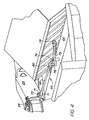
- FIG. 4
- is a view similar to that of FIG. 3 but showing a linkage connected between the tongue and the access door in accordance with a second embodiment of the invention.
- FIG. 5
- is a schematic representation of a third embodiment of the invention showing a hydraulic door-operating cylinder coupled to the door and to the hydraulic tongue swing cylinder in a hydraulic circuit.
- Referring now to FIGS. 1-3, there is shown a
mower 10 in the form of a side-pull mower-conditioner including carrier ormain frame 12 including across beam 14 extending transversely to a normal direction of travel and having opposite ends joined to depending wheel-support legs 16.Wheel support arms 18 are respectively pivoted to lower ends of thelegs 16 bypins 19, with only the left-hand arm 18 being shown. Hydraulic wheel actuatingcylinders 20 are coupled between brackets provided at upper rear locations of thelegs 16 and rear ends of thewheel support arms 18.Ground wheels 21 are mounted to the rear ends of thewheel support arms 18. - The
main frame 12 further includes a drafttongue support structure 22 which is joined to, and projects forwardly from, a leftward region of thecross beam 14, however, the particular location of the tongue support structure on thebeam 14 is not important to the present invention. Adraft tongue 24 has a rear end coupled to a forward end of thesupport structure 22 by avertical pin 26 which establishes an upright axis about which thetongue 24 may pivot horizontally. Coupled between thesupport structure 22 and thedraft tongue 24 is an extensible and retractablehydraulic cylinder 28, with the latter being shown in a fully retracted position wherein it positions thetongue 24 in a leftmost working position. It is to be noted that basic aspects of the present invention require only that thetongue 24 somehow be swung about the axis of thepin 26. For example, in lieu of thecylinder 28, any well-known remotely releasable coupling could be established between thetongue 24 andbeam 14, which when released permits thetongue 24 to pivot about thepin 26 by driving the towing tractor in an appropriate direction to effect swinging of thetongue 24 in a desired direction. - A
crop harvesting platform 30 includes aplatform frame 32 includingopposite side walls 34 joined by arear frame structure 36. Theframe 32 is suspended from thecarrier frame 12 by a three-bar linkage including a lower pair oflinks 38 and anupper link 40. The lower pair oflinks 38 is respectively located at opposite sides of theplatform 30 and has rear ends respectively pivotally coupled to the pair ofwheel support arms 18 and have front ends respectively pivotally coupled to lower rear locations of theplatform frame structure 36. A pair ofcounterbalance springs 42 have upper ends respectively coupled to upper front locations of the pair oflegs 16 and have lower ends respectively coupled to lower rear locations of theplatform frame member 36. - Thus, it will be appreciated that the
platform 30 may be moved between a lowered working position and a raised transport position through operation of thehydraulic cylinders 20 for adjusting thewheels 21 relative to theframe 12. - The
platform 30 includes a forward, generally horizontal top wall which extends between theopposite side walls 34. The top wall includes a relatively narrow, fixed rearrectangular section 44 and a front rectangular section including a minor, fixed left-hand portion 48, and a major right-hand portion forming anaccess door 50 that is mounted to a forward edge of therear section 44 by ahorizontal hinge assembly 52 that allows thedoor 50 to pivot vertically. Fixed to a forward edge of theaccess door 50 is aflexible shield 54 that hangs vertically in front of a rotary cutter bar (the cutter bar has been omitted from FIG. 2 for the sake of simplicity) when theplatform 30 is not in use. Aflexible shield 56 is likewise mounted to a forward edge of the top wall left-handminor portion 48. Thus, it will be appreciated that when it is desired to gain access to the rotary cutter bar located within the enclosure defined by thetop wall portion 50 and theflexible shield 54. This may be done by pivoting theaccess door 50, together with theflexible shield 54, upwardly about thehinge assembly 52 from its operative position, shown in FIG. 1, to its open position, shown in FIG. 2. - Up to this point, the described structure is conventional.
- The present invention comes into play when the
access door 50 is swung into its open position. Specifically, fixed to a lower right-hand surface location of a rear region of thetongue 24 is a triangular door engaging plate ormember 60. The doorengaging plate 60 may be of any effective shape and is here shown as having a shape of a right triangle, with the hypotenuse being fixed along thetongue 24, with the sides forming the right angle being located behind an upper left-hand corner of theaccess door 50, and with anedge 62 of theplate 60 extending forwardly from the right angle and making an angle of about 30° with thetongue 24. Theedge 62 is engaged by, and supports theopen access door 50 in a disposition where it is inclined gradually to the rear from thehinge assembly 52. Theedge 62 is so disposed relative to theaccess door 50, that as thetongue 24 is swung toward thedoor 50, thedoor 50 is pivoted forwardly and closed before it is contacted by thetongue 24 itself. Therefore, if an operator should inadvertently leave theaccess door 50 in its open position and then resume an operation where it is desired to reposition themower 10 relative to the towing tractor by swinging thetongue 24 toward theopen access door 50, such an operation can be done without damaging thedoor 50 by engaging it with thetongue 24 since thedoor 50 will close before such an engagement occurs. While it is convenient in the disclosed embodiment for the doorengaging plate 60 to be used to support theopen access door 50, it will be appreciated that thedoor 50 may be supported in its open position by other structure. - Referring now to FIG. 4 there is shown an alternate embodiment here like structure is indicated by the same reference numerals given above. The only difference in structure is that instead of providing the
tongue 24 with a doorengaging plate 60, alinkage 66 is mounted between thetongue 24 and a central location of theaccess door 50. Specifically, thelinkage 66 includes alink 68 having a left-hand end pivotally mounted, as at anupright pin 70, to a pair of vertically spacedears 71 fixed to thetongue 24. A bell-crank 72 is mounted to therear section 44 of the top wall of theplatform 30 for pivoting about anupright pin 74 located to the rear of a central location of theaccess door 50. The bell-crank 72 includes a relatively short leg, which carries a swivel-eye 76 in which thelink 68 is mounted for free sliding movement, the short leg being joined to, and making an angle of about 90° with, a relatively long leg which carries aroller 78 at its free end. As considered when thetongue 24 is in its left-most position and with theaccess door 50 open, as shown in FIG. 4, the short leg of the bell-crank 72 ends generally perpendicular to thedoor 50 while the long leg of the bell-crank 72 extends generally parallel to theaccess door 50 with theroller 78 engaging theopen access door 50. Anabutment 80, which may be defined by a washer secured to therod 68, is positioned for engaging the swivel-eye 76 so as to cause the bell-crank 72 to pivot resulting in theroller 78 being swung forwardly a distance sufficient for closing thedoor 50 when thetongue 24 is swung toward the door. The length of therod 68 which extends beyond the swivel-eye from the tongue ensures that the rod will remain within the swivel-eye 76 during operation with thedoor 50 in its closed operating position. The relative lengths of the short and long legs of bell-crank 72 ensures that sufficient motion will be imparted to accessdoor 50 by the pivoting bell-crank 72 in response to movement of thetongue 24 for closing theaccess door 50 prior to the tongue reaching the door when swung toward it. For a simpler solution, thelink 68 could be pivotally coupled directly to short leg of the bell-crank 72. This would result in the bell-crank 72 pivoting when thetongue 24 is swung subsequent to thedoor 50 being closed. - Referring now to FIG. 5, there is shown a schematic of a third embodiment of the invention. The difference between this embodiment and the second embodiment is that instead of connecting a linkage between the
tongue 24 and theaccess door 50 to ensure that the latter is closed prior to being engaged and possibly damaged by the tongue when thedoor 50 is inadvertently left open and thetongue 24 is swung toward thedoor 50, a hydraulicdoor closing cylinder 82 is mounted between respective central regions of thetop wall section 44 anddoor 50. The rod end of thecylinder 82 is coupled to thedoor 50 through the agency of abracket 84 fixed to thedoor 50 and containing, as considered when theaccess door 50 is closed, a fore-and-aft elongated,lost motion slot 86, having a purpose explained below. The rod end of thecylinder 82 is equipped with a clevis that straddles thebracket 84 and is coupled to it by apin 88 located in the lostmotion slot 86, with thepin 88 being located in the remote end of theslot 86 when thedoor 50 is open, as shown in the drawing. - For effecting operation of the
door closing cylinder 82 in response to thetongue swing cylinder 28 being operated to swing thetongue 24 toward theopen access door 50, there is provided ahydraulic circuit 90 including ahydraulic pump 92 andsump 94 coupled to a four-way, three-position control valve 96 having a first port coupled by a first branched supply/returnconduit 98 to respective rod ends of thetongue cylinder 28 and adoor closing cylinder 82. A second branched supply/returnconduit 100 couples a second port of thecontrol valve 96 to the head end of thedoor closing cylinder 82 and to apriority valve 102 including a first path to the head end of thetongue cylinder 28, which is blocked in the direction of thecylinder 28 by acheck valve 104, and a second route to the head end of thecylinder 28, which is normally blocked by a pressure-responsive valve 106. - In operation, assuming that the
access door 50 has been inadvertently left open and that the operator has resumed operation and desires to reposition themower 10 relative to the towing tractor, thevalve 96 will be shifted upwardly from its neutral position shown in FIG. 5. Pressure fluid will immediately be routed to the head end of thedoor closing cylinder 82 so as to pressurize the head end of thedoor cylinder 82 while the rod end is coupled to thesump 94. No pressure fluid will at this time be routed to thetongue cylinder 28 since the pressureresponsive valve 106 of thesequencing valve 102 will block flow to the head end of thetongue swing cylinder 28. Thedoor 50 will close upon only a partial extension of thecylinder 82 taking place. When thecylinder 82 has become fully extended, the pressure in the conduit will rise and cause the pressureresponsive valve 106 to shift to its open position. Thetongue swing cylinder 28 will then extend to swing thetongue 24 to the desired position whereupon the operator will return thecontrol valve 96 to its neutral position. Thereafter, thevalve 96 may be shifted to cause other desired movements of thetongue 24 with thedoor closing cylinder 82 extending or retracting without effecting the position of theclosed access door 50 due to the lostmotion slot 86. Because thetongue swing cylinder 28 and thedoor closing cylinder 82 are coupled in parallel, and the resistance to movement offered by thedoor 50 is much less than the force required to swing thetongue 24, it may be possible to eliminate thesequencing valve 102 since thecylinder 82 would normally extend prior to thecylinder 28 extending.
Claims (6)
- Mower (10) including a carrier frame (12) being supported on ground wheels (21), a tongue (24) having a region mounted to said carrier frame (12) for pivoting about an upright axis, a housing including an access door (50) being mounted for pivoting vertically from a working position to an open position wherein said door (50) is in a path of movement of said tongue (24) when the latter is pivoted, characterized in that said tongue (24) is operatively connected to said door (50) so as to cause said door (50) to be moved to said working position in response to said tongue (24) moving toward said door (50).
- Mower according to claim 1, characterized in that said operative connection is established by a door engaging member (60) mounted to said tongue (24) in a location where it engages said door (50) when said door (50) is in said open position.
- Mower according to claim 1 or 2, characterized in that said door engaging member (60) is specially shaped, in particular like a triangular member, so that it causes said door (50) to be closed prior to being engaged by said tongue (24) when said tongue (24) is moved toward said access door (50).
- Mower according to one or more of the preceding claim, characterized in that said operative connection is established by a linkage (66) coupled between said tongue (24) and access door (50).
- Mower according to claim 4, characterized in that said linkage (66) includes a one-way connection which transfers motion of said tongue (24) to said door (50) to effect closing of the door (50) only when said tongue (24) is moved toward said door (50).
- Mower according to claim 1, characterized in that a tongue actuator (28) in the form of a first hydraulic cylinder (28) is connected between said carrier frame (12) and said tongue (24); a second hydraulic actuator (82) being coupled to said access door (50) and coupled in a hydraulic circuit (90) with said first hydraulic actuator (28) such that when said first hydraulic cylinder (28) is actuated said second hydraulic actuator (82) will sequence prior to said first hydraulic cylinder (28) so as to cause said door (50) to close prior to swinging movement of said tongue (24).
Applications Claiming Priority (2)
| Application Number | Priority Date | Filing Date | Title |
|---|---|---|---|
| US805858 | 2004-03-22 | ||
| US10/805,858 US6845603B1 (en) | 2004-03-22 | 2004-03-22 | Side-pull mower-conditioner tongue operatively associated with access door for closing door when tongue is swung |
Publications (2)
| Publication Number | Publication Date |
|---|---|
| EP1582094A1 EP1582094A1 (en) | 2005-10-05 |
| EP1582094B1 true EP1582094B1 (en) | 2007-10-24 |
Family
ID=34063639
Family Applications (1)
| Application Number | Title | Priority Date | Filing Date |
|---|---|---|---|
| EP05101768A Not-in-force EP1582094B1 (en) | 2004-03-22 | 2005-03-08 | Mower having an access door and a tongue |
Country Status (4)
| Country | Link |
|---|---|
| US (1) | US6845603B1 (en) |
| EP (1) | EP1582094B1 (en) |
| AT (1) | ATE376349T1 (en) |
| DE (1) | DE602005002967T2 (en) |
Families Citing this family (9)
| Publication number | Priority date | Publication date | Assignee | Title |
|---|---|---|---|---|
| US7047714B1 (en) * | 2005-02-02 | 2006-05-23 | Deere & Company | Tongue swing cylinder arrangement for rotary side-pull mower-conditioner |
| US7726109B2 (en) | 2007-10-30 | 2010-06-01 | Vermeer Manufacturing Co. | Four-bar linkage for suspending a header for an agricultural implement |
| US7658056B2 (en) | 2007-10-30 | 2010-02-09 | Vermeer Manufacturing Co. | System for folding an agricultural machine with a floating work tool |
| US8112977B2 (en) * | 2010-02-18 | 2012-02-14 | Cnh America Llc | Disc mower narrow transport frame |
| FR2966322B1 (en) * | 2010-10-21 | 2012-11-02 | Kuhn Sa | HARVESTING MACHINE WITH A WEIGHTING DEVICE |
| US9648803B2 (en) | 2012-08-07 | 2017-05-16 | Cnh Industrial America Llc | Bi-fold hoods for agricultural equipment |
| RU2527023C1 (en) * | 2013-03-12 | 2014-08-27 | Александр Юрьевич Константинов | Mechanism for balancing cutting unit of machine for harvesting agricultural plants, for instance cabbage |
| SE537796C2 (en) * | 2013-05-23 | 2015-10-20 | Imsson Natur Teknik Ab | Apparatus and method for treating a crop |
| DE102021134489A1 (en) | 2021-12-23 | 2023-06-29 | Pöttinger Landtechnik Gmbh | Agricultural attachment |
Family Cites Families (7)
| Publication number | Priority date | Publication date | Assignee | Title |
|---|---|---|---|---|
| US3881303A (en) * | 1973-07-12 | 1975-05-06 | Deere & Co | Elastomeric hinge for a swingable agricultural machine element |
| DE3400735A1 (en) * | 1984-01-11 | 1985-07-18 | Klöckner-Humboldt-Deutz AG Zweigniederlassung Fahr, 7702 Gottmadingen | Mowing machine |
| US4787196A (en) * | 1986-03-31 | 1988-11-29 | New Holland Inc. | Self-cleaning rotor assembly |
| US5272859A (en) * | 1992-04-14 | 1993-12-28 | Hay & Forage Industries | Mechanical drive center pivot mower conditioner |
| US5964076A (en) * | 1997-02-05 | 1999-10-12 | Gehl Company | Mower conditioner gear box steering device |
| US6082085A (en) * | 1998-05-13 | 2000-07-04 | Agco Corporation | Foliage mowing implement having mechanical drive with main gearbox rotation |
| US6718747B2 (en) * | 2001-07-09 | 2004-04-13 | Deere & Company | Rotary cutter parking stand |
-
2004
- 2004-03-22 US US10/805,858 patent/US6845603B1/en not_active Expired - Lifetime
-
2005
- 2005-03-08 EP EP05101768A patent/EP1582094B1/en not_active Not-in-force
- 2005-03-08 AT AT05101768T patent/ATE376349T1/en not_active IP Right Cessation
- 2005-03-08 DE DE602005002967T patent/DE602005002967T2/en not_active Expired - Lifetime
Also Published As
| Publication number | Publication date |
|---|---|
| ATE376349T1 (en) | 2007-11-15 |
| EP1582094A1 (en) | 2005-10-05 |
| DE602005002967D1 (en) | 2007-12-06 |
| DE602005002967T2 (en) | 2008-08-07 |
| US6845603B1 (en) | 2005-01-25 |
Similar Documents
| Publication | Publication Date | Title |
|---|---|---|
| US9622404B2 (en) | Integral lateral transport of a mower | |
| CA1277146C (en) | Mower height adjustment mechanism | |
| CA2092668C (en) | Hinged-blade roadside mower | |
| CA2313849E (en) | Retractable snow plow wing assembly | |
| US5775075A (en) | Articulated boom assembly | |
| US7673439B2 (en) | Agricultural machine for swathing products lying on the ground | |
| CA1211084A (en) | Boom suspension and lift assembly | |
| EP3504950B1 (en) | Lateral transport system for harvester and method of using the same | |
| CA2327995C (en) | Mowing implement | |
| US4460193A (en) | Pull type swather assembly and mounting therefor | |
| US6845603B1 (en) | Side-pull mower-conditioner tongue operatively associated with access door for closing door when tongue is swung | |
| CA2020515C (en) | Mower | |
| US5012608A (en) | Spray boom | |
| US2662561A (en) | Timber-moving saw attachment for tractors | |
| US4442660A (en) | High lift mechanism for rear end of front mounted mower | |
| US4907400A (en) | Agricultural mower having means for raising the reel to a clearing height when the cutter bar engages an obstacle | |
| US3110146A (en) | Mower attachment for tractors | |
| EP3097771A1 (en) | Forestry machine | |
| US3334476A (en) | Resilient support for a rotary mower housing | |
| US4972661A (en) | Agricultural mower having a displaceable conditioning roller assembly | |
| US7207166B2 (en) | Side-pull mower-conditioner tongue pivotably mounted to platform frame at location inboard of platform gearbox | |
| US7178605B2 (en) | Agricultural toolbar float system | |
| GB2469836A (en) | Lifting Mechanism for an agricultural implement | |
| US2986863A (en) | Pick-up | |
| EP0507408B1 (en) | An agricultural machine |
Legal Events
| Date | Code | Title | Description |
|---|---|---|---|
| PUAI | Public reference made under article 153(3) epc to a published international application that has entered the european phase |
Free format text: ORIGINAL CODE: 0009012 |
|
| AK | Designated contracting states |
Kind code of ref document: A1 Designated state(s): AT BE BG CH CY CZ DE DK EE ES FI FR GB GR HU IE IS IT LI LT LU MC NL PL PT RO SE SI SK TR |
|
| AX | Request for extension of the european patent |
Extension state: AL BA HR LV MK YU |
|
| 17P | Request for examination filed |
Effective date: 20060405 |
|
| AKX | Designation fees paid |
Designated state(s): AT BE BG CH CY CZ DE DK EE ES FI FR GB GR HU IE IS IT LI LT LU MC NL PL PT RO SE SI SK TR |
|
| GRAP | Despatch of communication of intention to grant a patent |
Free format text: ORIGINAL CODE: EPIDOSNIGR1 |
|
| GRAS | Grant fee paid |
Free format text: ORIGINAL CODE: EPIDOSNIGR3 |
|
| GRAA | (expected) grant |
Free format text: ORIGINAL CODE: 0009210 |
|
| AK | Designated contracting states |
Kind code of ref document: B1 Designated state(s): AT BE BG CH CY CZ DE DK EE ES FI FR GB GR HU IE IS IT LI LT LU MC NL PL PT RO SE SI SK TR |
|
| REG | Reference to a national code |
Ref country code: GB Ref legal event code: FG4D |
|
| REG | Reference to a national code |
Ref country code: CH Ref legal event code: EP |
|
| REG | Reference to a national code |
Ref country code: IE Ref legal event code: FG4D |
|
| REF | Corresponds to: |
Ref document number: 602005002967 Country of ref document: DE Date of ref document: 20071206 Kind code of ref document: P |
|
| PG25 | Lapsed in a contracting state [announced via postgrant information from national office to epo] |
Ref country code: SE Free format text: LAPSE BECAUSE OF FAILURE TO SUBMIT A TRANSLATION OF THE DESCRIPTION OR TO PAY THE FEE WITHIN THE PRESCRIBED TIME-LIMIT Effective date: 20080124 Ref country code: LI Free format text: LAPSE BECAUSE OF FAILURE TO SUBMIT A TRANSLATION OF THE DESCRIPTION OR TO PAY THE FEE WITHIN THE PRESCRIBED TIME-LIMIT Effective date: 20071024 Ref country code: CH Free format text: LAPSE BECAUSE OF FAILURE TO SUBMIT A TRANSLATION OF THE DESCRIPTION OR TO PAY THE FEE WITHIN THE PRESCRIBED TIME-LIMIT Effective date: 20071024 Ref country code: ES Free format text: LAPSE BECAUSE OF FAILURE TO SUBMIT A TRANSLATION OF THE DESCRIPTION OR TO PAY THE FEE WITHIN THE PRESCRIBED TIME-LIMIT Effective date: 20080204 |
|
| REG | Reference to a national code |
Ref country code: CH Ref legal event code: PL |
|
| PG25 | Lapsed in a contracting state [announced via postgrant information from national office to epo] |
Ref country code: BG Free format text: LAPSE BECAUSE OF FAILURE TO SUBMIT A TRANSLATION OF THE DESCRIPTION OR TO PAY THE FEE WITHIN THE PRESCRIBED TIME-LIMIT Effective date: 20080124 Ref country code: IS Free format text: LAPSE BECAUSE OF FAILURE TO SUBMIT A TRANSLATION OF THE DESCRIPTION OR TO PAY THE FEE WITHIN THE PRESCRIBED TIME-LIMIT Effective date: 20080224 Ref country code: SI Free format text: LAPSE BECAUSE OF FAILURE TO SUBMIT A TRANSLATION OF THE DESCRIPTION OR TO PAY THE FEE WITHIN THE PRESCRIBED TIME-LIMIT Effective date: 20071024 Ref country code: PL Free format text: LAPSE BECAUSE OF FAILURE TO SUBMIT A TRANSLATION OF THE DESCRIPTION OR TO PAY THE FEE WITHIN THE PRESCRIBED TIME-LIMIT Effective date: 20071024 Ref country code: PT Free format text: LAPSE BECAUSE OF FAILURE TO SUBMIT A TRANSLATION OF THE DESCRIPTION OR TO PAY THE FEE WITHIN THE PRESCRIBED TIME-LIMIT Effective date: 20080324 Ref country code: LT Free format text: LAPSE BECAUSE OF FAILURE TO SUBMIT A TRANSLATION OF THE DESCRIPTION OR TO PAY THE FEE WITHIN THE PRESCRIBED TIME-LIMIT Effective date: 20071024 |
|
| ET | Fr: translation filed | ||
| PG25 | Lapsed in a contracting state [announced via postgrant information from national office to epo] |
Ref country code: AT Free format text: LAPSE BECAUSE OF FAILURE TO SUBMIT A TRANSLATION OF THE DESCRIPTION OR TO PAY THE FEE WITHIN THE PRESCRIBED TIME-LIMIT Effective date: 20071024 |
|
| PG25 | Lapsed in a contracting state [announced via postgrant information from national office to epo] |
Ref country code: DK Free format text: LAPSE BECAUSE OF FAILURE TO SUBMIT A TRANSLATION OF THE DESCRIPTION OR TO PAY THE FEE WITHIN THE PRESCRIBED TIME-LIMIT Effective date: 20071024 Ref country code: CZ Free format text: LAPSE BECAUSE OF FAILURE TO SUBMIT A TRANSLATION OF THE DESCRIPTION OR TO PAY THE FEE WITHIN THE PRESCRIBED TIME-LIMIT Effective date: 20071024 |
|
| PG25 | Lapsed in a contracting state [announced via postgrant information from national office to epo] |
Ref country code: SK Free format text: LAPSE BECAUSE OF FAILURE TO SUBMIT A TRANSLATION OF THE DESCRIPTION OR TO PAY THE FEE WITHIN THE PRESCRIBED TIME-LIMIT Effective date: 20071024 Ref country code: RO Free format text: LAPSE BECAUSE OF FAILURE TO SUBMIT A TRANSLATION OF THE DESCRIPTION OR TO PAY THE FEE WITHIN THE PRESCRIBED TIME-LIMIT Effective date: 20071024 |
|
| PLBE | No opposition filed within time limit |
Free format text: ORIGINAL CODE: 0009261 |
|
| STAA | Information on the status of an ep patent application or granted ep patent |
Free format text: STATUS: NO OPPOSITION FILED WITHIN TIME LIMIT |
|
| 26N | No opposition filed |
Effective date: 20080725 |
|
| PG25 | Lapsed in a contracting state [announced via postgrant information from national office to epo] |
Ref country code: MC Free format text: LAPSE BECAUSE OF NON-PAYMENT OF DUE FEES Effective date: 20080331 |
|
| PG25 | Lapsed in a contracting state [announced via postgrant information from national office to epo] |
Ref country code: GR Free format text: LAPSE BECAUSE OF FAILURE TO SUBMIT A TRANSLATION OF THE DESCRIPTION OR TO PAY THE FEE WITHIN THE PRESCRIBED TIME-LIMIT Effective date: 20080125 Ref country code: EE Free format text: LAPSE BECAUSE OF FAILURE TO SUBMIT A TRANSLATION OF THE DESCRIPTION OR TO PAY THE FEE WITHIN THE PRESCRIBED TIME-LIMIT Effective date: 20071024 |
|
| PG25 | Lapsed in a contracting state [announced via postgrant information from national office to epo] |
Ref country code: FI Free format text: LAPSE BECAUSE OF FAILURE TO SUBMIT A TRANSLATION OF THE DESCRIPTION OR TO PAY THE FEE WITHIN THE PRESCRIBED TIME-LIMIT Effective date: 20071024 |
|
| PGFP | Annual fee paid to national office [announced via postgrant information from national office to epo] |
Ref country code: IE Payment date: 20090325 Year of fee payment: 5 |
|
| PGFP | Annual fee paid to national office [announced via postgrant information from national office to epo] |
Ref country code: NL Payment date: 20090324 Year of fee payment: 5 |
|
| PG25 | Lapsed in a contracting state [announced via postgrant information from national office to epo] |
Ref country code: CY Free format text: LAPSE BECAUSE OF FAILURE TO SUBMIT A TRANSLATION OF THE DESCRIPTION OR TO PAY THE FEE WITHIN THE PRESCRIBED TIME-LIMIT Effective date: 20071024 |
|
| PGFP | Annual fee paid to national office [announced via postgrant information from national office to epo] |
Ref country code: IT Payment date: 20090327 Year of fee payment: 5 |
|
| PGFP | Annual fee paid to national office [announced via postgrant information from national office to epo] |
Ref country code: BE Payment date: 20090430 Year of fee payment: 5 |
|
| GBPC | Gb: european patent ceased through non-payment of renewal fee |
Effective date: 20090308 |
|
| PG25 | Lapsed in a contracting state [announced via postgrant information from national office to epo] |
Ref country code: GB Free format text: LAPSE BECAUSE OF NON-PAYMENT OF DUE FEES Effective date: 20090308 |
|
| PG25 | Lapsed in a contracting state [announced via postgrant information from national office to epo] |
Ref country code: LU Free format text: LAPSE BECAUSE OF NON-PAYMENT OF DUE FEES Effective date: 20080308 Ref country code: HU Free format text: LAPSE BECAUSE OF FAILURE TO SUBMIT A TRANSLATION OF THE DESCRIPTION OR TO PAY THE FEE WITHIN THE PRESCRIBED TIME-LIMIT Effective date: 20080425 |
|
| PG25 | Lapsed in a contracting state [announced via postgrant information from national office to epo] |
Ref country code: TR Free format text: LAPSE BECAUSE OF FAILURE TO SUBMIT A TRANSLATION OF THE DESCRIPTION OR TO PAY THE FEE WITHIN THE PRESCRIBED TIME-LIMIT Effective date: 20071024 |
|
| BERE | Be: lapsed |
Owner name: DEERE & CY Effective date: 20100331 |
|
| REG | Reference to a national code |
Ref country code: NL Ref legal event code: V1 Effective date: 20101001 |
|
| PG25 | Lapsed in a contracting state [announced via postgrant information from national office to epo] |
Ref country code: IE Free format text: LAPSE BECAUSE OF NON-PAYMENT OF DUE FEES Effective date: 20100308 Ref country code: NL Free format text: LAPSE BECAUSE OF NON-PAYMENT OF DUE FEES Effective date: 20101001 |
|
| PG25 | Lapsed in a contracting state [announced via postgrant information from national office to epo] |
Ref country code: BE Free format text: LAPSE BECAUSE OF NON-PAYMENT OF DUE FEES Effective date: 20100331 |
|
| PG25 | Lapsed in a contracting state [announced via postgrant information from national office to epo] |
Ref country code: IT Free format text: LAPSE BECAUSE OF NON-PAYMENT OF DUE FEES Effective date: 20100308 |
|
| REG | Reference to a national code |
Ref country code: FR Ref legal event code: PLFP Year of fee payment: 12 |
|
| REG | Reference to a national code |
Ref country code: FR Ref legal event code: PLFP Year of fee payment: 13 |
|
| PGFP | Annual fee paid to national office [announced via postgrant information from national office to epo] |
Ref country code: DE Payment date: 20170301 Year of fee payment: 13 Ref country code: FR Payment date: 20170327 Year of fee payment: 13 |
|
| REG | Reference to a national code |
Ref country code: DE Ref legal event code: R119 Ref document number: 602005002967 Country of ref document: DE |
|
| PG25 | Lapsed in a contracting state [announced via postgrant information from national office to epo] |
Ref country code: DE Free format text: LAPSE BECAUSE OF NON-PAYMENT OF DUE FEES Effective date: 20181002 |
|
| PG25 | Lapsed in a contracting state [announced via postgrant information from national office to epo] |
Ref country code: FR Free format text: LAPSE BECAUSE OF NON-PAYMENT OF DUE FEES Effective date: 20180331 |