EP1580696A2 - Horizontally structured CAD/CAM modeling - Google Patents
Horizontally structured CAD/CAM modeling Download PDFInfo
- Publication number
- EP1580696A2 EP1580696A2 EP05075643A EP05075643A EP1580696A2 EP 1580696 A2 EP1580696 A2 EP 1580696A2 EP 05075643 A EP05075643 A EP 05075643A EP 05075643 A EP05075643 A EP 05075643A EP 1580696 A2 EP1580696 A2 EP 1580696A2
- Authority
- EP
- European Patent Office
- Prior art keywords
- feature
- coordinate system
- parent
- datum
- associative relationship
- Prior art date
- Legal status (The legal status is an assumption and is not a legal conclusion. Google has not performed a legal analysis and makes no representation as to the accuracy of the status listed.)
- Withdrawn
Links
Images















Classifications
-
- G—PHYSICS
- G06—COMPUTING OR CALCULATING; COUNTING
- G06T—IMAGE DATA PROCESSING OR GENERATION, IN GENERAL
- G06T19/00—Manipulating three-dimensional [3D] models or images for computer graphics
Definitions
- CAD/CAM Computer-Aided Design and Computer-Aided Manufacturing
- a method for converting a vertically structured CAD/CAM model to a horizontally structured CAD/CAM model comprising: identifying and establishing a base feature; establishing a parent coordinate system; identifying a parent modeling element; identifying each dependency for each feature from the parent modeling element; restructuring each dependency for each feature for placement, such that each feature exhibits a direct associative relationship with a reference feature; and restructuring each dependency for each feature for positioning, such that each feature exhibits a direct associative relationship with another reference feature.
- a horizontally structured CAD/CAM model comprising: a reference feature; a base feature; and a feature.
- the CAD/CAM model is converted from a vertically structured CAD/CAM model by restructuring each dependency for each feature for placement, such that each feature exhibits a direct associative relationship with the reference feature, and restructuring each dependency for each feature for positioning, such that each feature exhibits a direct associative relationship with another reference feature.
- Also disclosed in yet another exemplary embodiment is a storage medium encoded with a machine-readable computer program code.
- the storage medium including instructions for causing a computer to implement the abovementioned method for converting a vertically structured CAD/CAM model to a horizontally structured CAD/CAM model.
- the computer data signal comprising code configured to cause a processor to implement the abovementioned method for converting a vertically structured CAD/CAM model to a horizontally structured CAD/CAM model.
- CAD/CAM computer-aided design and computer aided manufacture
- the methodologies of the exemplary embodiments may be implemented on any CAD/CAM software package that supports (a) reference planes or their Cartesian equivalents, (b) parametric modeling or its equivalent, and (c) feature modeling or its equivalents.
- CAD/CAM software packages that meet the three criteria above and that would therefore be suitable.
- Other suitable CAD/CAM software packages that meet the three criteria above and that would therefore be suitable.
- other suitable software packages include, but may not be limited to, SOLID EDGE®, also by Unigraphics®, and CATIA® by IBM®.
- the phrases "datum planes", "parametric modeling” and “features” are phrases derived from the Unigraphics® documentation and may not necessarily be used in other software packages. Therefore, their functional definitions are set out below.
- “Horizontal modeling” is a methodology employed to add features to a model, preferably by establishing an exclusive associative relationships, in particular, parent/child relationships between a set of reference planes and each feature.
- the reference planes themselves may, but need not be, children of a parent base feature from which a horizontally structured model is developed. Since each added feature of the model is related exclusively to a reference coordinate, then individual features may be added, edited, suppressed or deleted individually without affecting the rest of the model.
- Model refers to the part that is being created via the CAD/CAM software.
- the model comprises a plurality of modeling elements including "features”.
- modeling elements or elements of model and similar phraseology have been used throughout this specification. Such terminology is intended to include, but not be limited to: a reference, a reference axis, a reference datum, a datum, a coordinate system, a reference set, a geometry, a linked geometry, a linked body, a virtual blank, a base feature, a product model, a master process model, a master product and process concurrent model, an extract, an in-process model, an extracted body, a modeling feature, modifying feature, a manufacturing feature, a process sheet, a drawing, a product drawing, a tool drawing, a fixture, a spreadsheet and the like as well as combinations of the foregoing.
- “Datum planes” refer to reference features that define Cartesian coordinates by which other features may be referenced to in space. In Unigraphics®, the datum planes are two-dimensional, but a plurality of datum planes may be added to a drawing to establish three-dimensional coordinates. These coordinates may be constructed relative to the model to move and rotate with the model. Regardless of how the coordinate system is created, for the purposes of this disclosure it should be possible to reference numerous features to the same coordinate system.
- Parametric modeling capabilities refers to the ability to place mathematical constraints or parameters on features of the model so that the features may be edited and changed later. Models that do not have this capability i.e., models that include non-editable features, are referred to as "dumb solids". Most CAD/CAM systems support parametric modeling.
- Primitive refers to Primitive features that are basic analytic shapes e.g., blocks, cylinders, cones and spheres. Primitives are nonassociative, meaning they are not associated to the geometry used to create them and are created in the model at the basic level. However, certain parameters may be edited. A primitive feature is usually the base feature of a model.
- Features refers to parts and details that combine to form the model.
- a "reference feature”, such as a coordinate system, datum, line, and the like is an imaginary feature that is treated and manipulated like a physical feature, but does not appear in the final physical model.
- a modeling feature, also denoted a form feature corresponds to the building blocks of a model, e.g., pads, bosses, holes, bores, and the like, as well as combinations including at least one of the foregoing.
- Modifying features are features directed to modification of a particular aspect of a feature. For example, blends, chamfers, and the like.
- Feature modeling is the ability to build up a model by adding and connecting a plurality of editable features. Not all CAD/CAM software supports this capability. AutoCAD®, for example, currently employs a wire-frame-and-skin methodology to build models rather than feature modeling.
- Associative relationship An aspect of feature modeling is the creation of associative relationships among models, model elements, features, and the like, as well as combinations of the foregoing, meaning the features are linked such that changes to one feature may alter the others with which it is associated.
- a particular exemplary associative relationship is a "parent/child relationship”.
- Parent/child relationship is a type of associative relationship among models, model elements, features, and the like, as well as combinations of the foregoing.
- a parent/child relationship between a first feature (parent) and a second feature (child) means that changes to the parent feature will affect the child feature (and any children of the child all the way down the familial line), but changes to the child will have no effect on the parent. Further, deletion of the parent results in deletion of all the children and progeny below it.
- the foregoing definition is intended to address associative relationships created as part of generating a model, notwithstanding associative relationships created because of the application of expression driven constraints applied to feature parameters.
- the present invention relates to the design and manufacture of a real-world object based upon a virtual CAD/CAM model. More particularly the methodologies for converting 3D models generated using "vertical" modeling techniques to horizontally structured 3D models. It will be appreciated that horizontal modeling ensures that a 3D model is configured so that features are substantially independent of the base feature and other features. Thereby, alterations, additions, and deletions of individual features (e.g., holes, bosses, etc.) may be accomplished without impacting a significant portion of the model.
- Horizontal modeling accomplishes such independence by configuring the 3D model such that added features are positioned and placed relative to independent coordinate system(s) (e.g., one or more datums)
- independent coordinate system(s) e.g., one or more datums
- vertically constructed models are constructed with numerous features exhibiting relationships with the base feature of the model.
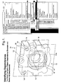
- the 3D model 10 includes a base feature 12 (shown as cylinder(0)) with various modeling form features 14 e.g., holes, bores, pads, bosses, and the like added thereto. Some modeling features 14 may also include modifying features 16 such as blends, chamfers, and the like as well.
- reference datum planes/axes 18 should preferably be the placed at the highest level e.g., first, because they are utilized later to establish a basic coordinate system and for creating additional parameterized coordinate systems/datum planes/axes 20 used for the placement and positioning of features 14.
- the base feature 12 is the base modeling element such as a linked body, cylinder, extruded sketch geometry, and the like that a model is "built” up from. Sketches (not shown) and modeling elements derived therefrom should preferably be second, as they are attached to reference planes 18. Modeling form features 14 used for creating the structure of the part being modeled follow, once again, because they are placed and positioned relative to the abovementioned coordinate systems 20 datum planes/axes 18.
- modeling form features 14 include, but are not limited to extrusions, bosses, holes, pads, and the like, as well as combinations including at least one of the foregoing.
- modifying features 16 such as blends and chamfers are usually the finishing features on a modeled part. It is preferred to have these modifying features 16 last because when you need to modify modeling features 14, these modifying features 16 can exhibit dependency issues with the modeling features 14 that being edited. In other words, these types of modifying features 16 e.g., blends and chamfers are configured to be dependent on a physical geometry of another modeling feature 14.
- Unigraphics® is a menu based CAD/CAM modeling environment. Within the Unigraphics® modeling environment are various toolbars/environments to facilitate model selection, generation, evaluation, and navigation of the various features, modeling elements and the like of a 3D model 10. For instance, Unigraphics® includes as a toolbar a menu-based model navigator 50 denoted as the Unigraphics® Model Navigator 50 to facilitate navigation and evaluation of the 3D model 10.
- the navigator 50 includes various facilities, processes, selection criteria, and the like referred to as functions 52 shown in the menus and sub-menus of the menu based navigator 50.
- functions 52 shown in the menus and sub-menus of the menu based navigator 50 tool bar will be referred to in capital letters.
- One such function 52 is the Object Dependency Browser.
- the various dependencies of the modeling elements 13 of the existing model 10 are identified as depicted in the process at block 202.
- a base feature 12 is identified (or established if necessary) to initiate the conversion as depicted at process block 204.
- One method to identify dependencies is by employing the Unigraphics® Model Navigator 10; Object Dependency Browser function 52, Select All Descendents sub-function 52 (or their equivalents in other modeling software packages).
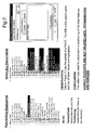
- Figure 3 also provides an illustration of the various dependencies for the existing model 10 as well as the menus and submenus of the Unigraphics® Model Navigator 50.
- the base feature 12 may readily be identified as the cylinder(0).
- references to various elements of he model 10 are followed by a numeral indicating an order in the model 10. This order is illustrative of a feature of Unigraphics® and not intended to indicate any particular hierarchy or dependency beyond the order in the model. It will be further appreciated that as referenced herein the numerals associated with particular modeling elements, e.g., features 14, datums 18 and the like will vary as the order of that element changes with the conversion.
- the existing model 10 is modified to include a new parent coordinate system 20 a reference feature.
- This new parent coordinate system 20 and its descendants e.g., other coordinate systems 20 and datums 18
- the coordinate system 20 is depicted as comprising three orthogonal datum planes 18 located at the modeling environment work coordinate system origin.
- other configurations for a coordinate system 20 are possible. For example, single planes, lines, as well combinations including at least one of the foregoing.
- an additional plane, or set of planes 18 is optionally established relative to the parent coordinate system 20 as depicted at process 207 to facilitate positioning and placement of the modeling features 14.
- the planes 10 are established in the same planes e.g., X, Y, and Z as the planes of the parent coordinate system 20 with offsets, shifting, rotations and the like as well as combinations of the foregoing as needed to facilitate positioning and placement of the modeling features 14.
- the existing model 10 is evaluated to ensure that no other feature of the existing model 10 is configured as a base feature 12 (e.g., a primitive). If others exist, these elements are reconfigured as modeling features 14 to facilitate the conversion as depicted at decision and process blocks 208 and 210 and converted with the modeling features 14 as described below.
- the reconfiguring includes generating a new form feature 14 with the same parameters as the "extra" base feature placed and positioned relative to the datums of the parent coordinate system 20 or another coordinate system 20 related to parent coordinate system 20.
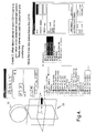
- the illustration in Figures 4 depicts the CYLINDER(1) as a base feature or primitive (a cylinder in the example).
- Figure 5 depicts the base feature 12 as well as the newly added feature 14, shown in the figures as BOSS(20), which is then re-ordered to precede the RIB(5) as depicted in Figure 6.
- Figure 6 depicts the "new" form feature as BOSS(5) "replacing" the RIB.
- BOSS(5) "replacing" the RIB.
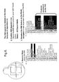
- the RIB(6) may not be deleted because of the feature dependencies that may be associated with it.
- first parent modeling element 13a and its descendants.
- all descendants of this first parent modeling element 13a may be suppressed (hidden) to clarify the working environment of the model 10 and avoid confusion as depicted at process block 211.
- the first parent modeling element 13a will most likely correspond to the replaced "multiple" base feature for which a modeling feature 14 is established as discussed for process block 208 and 210, if such a modeling feature 14 was established.
- the first parent modeling element 13a may but need not be a modeling feature 14.
- the first parent modeling element 13a could also be another base feature 12, primitive, modeling feature and the like.
- Figure 6 depicts the RIB(6) in the Feature Dependency Table as the first parent modeling element 13 as well as all of its feature dependencies.
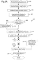
- the methodology 200 continues for the restructuring of each feature with process 214 as depicted on Figure 2B of the existing model 10 to form the new horizontally structured model.
- the methodology 200 continues as depicted at process block 215, with the identification of the various feature dependencies associated with the first parent modeling element 13a from process 212.
- decision block 216 it is determined for each modeling element 13 dependent from the first parent modeling element 13a, whether datums 18 are established in the existing model 10 governing the placement of a particular modeling element 13 or modeling feature 14. If not, the methodology 200 optionally includes establishing a new datum or datums 18 or coordinate system 20 dependent from the parent coordinate system 20, preferably, but not necessarily ordered just after the parent coordinate system 20 to govern the placement of this modeling feature 14 as depicted at process block 218.
- the datum 18 may alternatively be reordered and attached to the parent coordinate system 20 and re-utilized to control the placement of the form feature as depicted at process block 220.
- the modeling feature 14 may employ a datum of the parent coordinate system 20 for placement as would be employed for horizontally structured modeling.
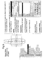
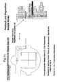
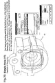
- FIGS 7-12 depict an illustration where the existing model 10 includes a DATUM_PLANE(7) used for one of placement or positioning of a modeling feature 14, RECTANGULAR_PAD(8).
- the Object Dependency Browser indicates DATUM_PLANE(7) has parent of Face - of RIB(6), therefore, DATUM_PLANE(7) is used for the placement of RECTANGULAR_PAD(8) (and RECTANGULAR_PAD(9)).
- Figures 8 and 9 depict the considerations for RECTANGULAR_PAD(8) and RECTANGULAR_PAD(9) which were originally created on DATUM_PLANE(7)and positioned with RIB(6).
- DATUM_PLANE(7) is reestablished for the placement with offset from the coordinate system 20 or the additional coordinate system 20 from process 207,
- DATUM_PLANE(7) is offset from DATUM_PLANE(2) in the X-Y plane by the thickness of the original RIB(6) to facilitate the placement of the RECTANGULAR_PAD(8) in the same plane as the face of the RIB(6) as depicted in Figures 9 and 10.
- Figure 11 depicts the re-attachment of RECTANGULAR_PAD(8) to the newly offset DATUM_PLANE(7).
- the methodology 200 optionally includes establishing new datum(s) 18 or coordinate system 20 dependent from the parent coordinate system, preferably, but not necessarily ordered just after the parent coordinate system to govern the positioning of this modeling feature 14 as depicted at process block 226.
- the datums 18 may be attached to the parent coordinate system 20 and re-utilized to control the positioning of the form feature as depicted at process block 228.
- the modeling feature 14 may employ datum(s) 18 of the parent coordinate system 20 for positioning as would be employed for horizontally structured modeling.
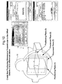
- Figure 12 also depicts before and after views of the Object Dependency Browser for the RECTANGULAR_PAD(8) indicating dependencies only to the DATUM_PLANE(3) and DATUM_PLANE(1) for positioning and DATUM_PLANE(7) for placement as indications of the structure of a horizontally structured model as opposed to DATUM_PLANE(7) for placement and the RIB(6) for positioning in the "before" view.
- Process block 231 indicates that the restructuring of the features 214 is reiterated for each modeling feature 14 dependent from the selected parent modeling element 13a established in process 212 of the existing model 10 until each modeling feature 14 is re-associated with datum planes 18 or coordinate systems 20 only as described above.
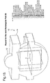
- Figure 13 depicts repeating process 214 for RECTANGULAR_PAD(9).
- Figure 14 depicts the restructuring of modeling feature 14, SIMPLE_HOLE(10).
- Figure 14 depicts the existing placement relative to CYLINDER(4) and positioning relative to the edges of another feature, RECTANGULAR_PAD(9)
- DATUM_PLANE(7) the placement is to a datum 18, once again in this instance DATUM_PLANE(7), while positioning is relative to the X and Y planes e.g., DATUM_PLANE(1) and DATUM_PLANE(3) of the coordinate system 20.
- DATUM_PLANE(7) the X and Y planes e.g., DATUM_PLANE(1) and DATUM_PLANE(3) of the coordinate system 20.
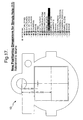
- SIMPLE_HOLE(11) and SIMPLE_HOLE(12) as depicted in Figures 16 - 18.
- modifying features 16 are preferably treated separately, as they are always tied to a particular modeling feature 14. Therefore, for convenience, and as a matter of good practice, modifying features 16 are preferably re-ordered to the end of the features dependency list for convenience.
- the CHAMFER(13) is preferably reordered to the end of the features as depicted becoming CHAMFER(20).
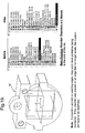
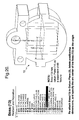
- Figures 20 - 32 the restructuring of the model 10 for modeling elements BOSS(13), DATUM(14), CYLINDRICAL _POCKET(15), CYLINDRICAL _POCKET(16), SIMPLE_HOLE(17), BOSS(18), BOSS(19) respectively.
- Figure 20 depicts the re-attachment of modeling element 14, BOSS(13.
- Figure 21 depicts the evaluation and deletion of DATUM(14) as it is no longer needed.
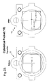
- Figures 22 and 23 depict the repositioning of CYLINDRICAL _POCKET(15). In the existing model, this modeling feature 14 was placed relative to DATUM_PLANE(7) and once restructured, it is positioned relative to DATUM_PLANE(1) and DATUM_PLANE(3).
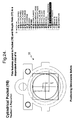
- Figure 24 - 27 depict the restructuring for CYLINDRICAL _POCKET(16).
- Figure 24 depicts that this modeling feature exhibits dependency to CYLINDRICAL POCKET(15) and is a parent of SIMPLE_HOLE(17).
- Modeling feature 14 CYLINDRICAL _POCKET(16) is restructured by reattaching to a datum plane 18 and repositioning.
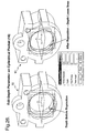
- Figure 25 depicts that CYLINDRICAL _POCKET(16) is placed relative to DATUM_PLANE(7), however, this placement will also require an adjustment to compensate the specified depth. Alternatively, it will be appreciated that another datum plane 18 with an appropriate offset could have been established, which would not have required a modification to the specified depth.
- Figures 26 and 27 depict the existing and new depths for CYLINDRICAL _POCKET(16).
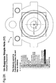
- SIMPLE_HOLE(17) is shown as a child of CYLINDRICAL _POCKET(16), and is restructured to eliminate the dependency.
- SIMPLE_HOLE(17) is attached DATUM_PLANE(7), and the depth of the hole is recalculated based on the new placement.
- Figures 29 and 30 depict the repositioning of modeling feature 14, SIMPLE_HOLE(17).
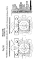
- BOSS(18) is repositioned relative to DATUM_PLANE(1) and DATUM_PLANE(3). As this modeling element was already placed relative to DATUM_PLANE(7), no modification for placement is necessary.
- Figure 32 depicts the repositioning.
- the methodology continues as depicted at process block 232 by determining if there is another "parent" modeling element 13b with dependencies. If so, the restructuring 214 continues for any modeling features 14 dependent from the next parent modeling element 13b and so on.
- any modeling elements no longer utilized may be deleted as depicted at process block 234.
- RIB(6) should now exhibit no dependencies and is deleted.
- DATUM_PLANE(7) now DATUM_PLANE(6) is reordered above the other features.
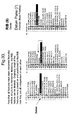
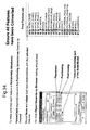
- Figure 34 it becomes apparent that for each modeling feature 14 in the model, placement and positioning is controlled by a coordinate system 20 and datum planes 18 independent of the base feature 12 (now CYLINDER(4) or any other feature. In this manner, the modeling features 14 may be individually treated, replaced, modified, deleted, and the like without any impact on the other features of the model. It will be appreciated that modifying features 16 because of their specific relationship to other modeling features 14 are still linked to other modeling features 14.
- Figure 34 depicts a final check of the feature dependencies of the restructured model to ensure the horizontal structure of the feature dependencies.
- the disclosed method may be embodied in the form of computer-implemented processes and apparatuses for practicing those processes.
- the method can also be embodied in the form of computer program code containing instructions embodied in tangible media, such as floppy diskettes, CD-ROMs, hard drives, or any other computer-readable storage medium, wherein, when the computer program code is loaded into and executed by a computer, the computer becomes an apparatus capable of executing the method.
- the present method can also be embodied in the form of computer program code, for example, whether stored in a storage medium, loaded into and/or executed by a computer, or as data signal transmitted whether a modulated carrier wave or not, over some transmission medium, such as over electrical wiring or cabling, through fiber optics, or via electromagnetic radiation, wherein, when the computer program code is loaded into and executed by a computer, the computer becomes an apparatus capable of executing the method.
- the computer program code segments configure the microprocessor to create specific logic circuits.
Landscapes
- Engineering & Computer Science (AREA)
- Computer Graphics (AREA)
- Computer Hardware Design (AREA)
- General Engineering & Computer Science (AREA)
- Software Systems (AREA)
- Physics & Mathematics (AREA)
- General Physics & Mathematics (AREA)
- Theoretical Computer Science (AREA)
- Processing Or Creating Images (AREA)
- Image Generation (AREA)
Abstract
Description
Claims (46)
- A method for converting a vertically structured CAD/CAM Model (10) to a horizontally structured CAD/CAM Model, comprising:identifying and establishing a base feature (12);establishing a parent coordinate system (20);identifying a parent modeling element (13a);identifying each dependency for each feature (14) from said parent modeling element (13a);restructuring each dependency for each said feature (14) for placement, such that each feature (14) exhibits a direct associative relationship with a reference feature (14); andrestructuring each dependency for each said feature (14) for positioning, such that each feature (14) exhibits a direct associative relationship with another reference feature (14).
- The method of Claim 1 wherein said reference feature includes:said parent coordinate system (20),a child coordinate system (20) exhibiting an associative relationship with said parent coordinate system (20),a first datum (18) exhibiting an associative relationship with at least one of said parent coordinate system (20) and said child coordinate system (20), anda second datum (18) exhibiting an associative relationship with said first datum (18).
- The method of Claim 1 wherein said another reference feature (14) includes:said parent coordinate system (20),said child coordinate system (20) exhibiting an associative relationship with said parent coordinate system (20),a third datum (18) exhibiting an associative relationship with at least one of said parent coordinate system (20) and said child coordinate system (20), anda fourth datum (18) exhibiting an associative relationship with said third datum (18).
- The method of Claim 1 further including identifying a primitive element in said vertically structured CAD/CAM Model (10).
- The method of Claim 4 further including converting said primitive element to a feature (14).
- The method of Claim 5 wherein said converting includes establishing a new feature (14) corresponding to said primitive element such that said new feature (14) exhibits an associative relationship with at least one of said parent coordinate system (20) and a child thereof for placement and positioning; and such that said new feature (14); exhibits an associative relationship with at least one of said parent coordinate system (20) and a child thereof for positioning.
- The method of Claim 6 wherein said associative relationship is a parent/child relationship.
- The method of Claim 1 wherein said base feature (12) corresponds to a selected primitive element in said vertically structured CAD/CAM Model (10).
- The method of Claim 1 wherein said establishing said parent coordinate system (20) comprises:creating a first datum (18) plane positioned and oriented relative to a reference;creating a second datum (18) plane positioned and oriented relative to said reference; andcreating a third datum (18) plane positioned and oriented relative to said reference.
- The method of Claim 6 wherein said first datum plane (18), said second datum plane (18) , and said third datum plane (18) are orthogonal.
- The method of Claim 1 wherein said feature (14) dependent from said parent modeling element (13a) exhibits a parent child relationship with at least one of said parent modeling element (13a) and a descendent thereof such that positioning and placement of said dependent features (14) is relative to said at least one of said parent modeling element (13a) and said descendent thereof.
- The method of Claim 11 wherein at least one of said associative relationship and said another associative relationship is a parent/child relationship.
- The method of Claim 1 wherein said restructuring each dependency for each said feature (14) for placement further includes:determining if said feature (14) is dependent on an existing datum (18) for placement;if said feature (14) is dependent on an existing datum (18) for placement, then at least one of:configuring a new reference feature for placement of said feature (14) wherein said reference feature is a descendent of said parent coordinate system (20) and establishing an associative relationship between said feature (14) and said new reference feature, then deleting said dependency,reconfiguring said existing datum (18) as a descendant of said parent coordinate system (20); andestablishing an associative relationship with at least one of said parent coordinate system (20) and a descendent reference feature therefrom and deleting said dependency.
- The method of Claim 13 wherein said associative relationship is a parent/child relationship.
- The method of Claim 1 wherein said restructuring each dependency for each said feature (14) for positioning further includes:determining if said feature (14) is dependent on at least one existing datum (18) for positioning;if said feature (14) is dependent on said at least one existing datum (18) for positioning, then at least one of:configuring a new reference feature for positioning of said feature (14) wherein said reference feature is a descendent of said parent coordinate system (20) and establishing an associative relationship between said feature (14) and said new reference feature, then deleting said dependency,reconfiguring said at least one existing datum (18) as a descendant of said parent coordinate system (20);establishing an associative relationship with at least one of said parent coordinate system (20) and a descendent reference feature therefrom and deleting said dependency.
- The method of Claim 15 wherein said associative relationship is a parent/child relationship.
- The method of Claim 1 wherein none of said features (14) exhibits an associative relationship with any other feature (14).
- The method of Claim 1 wherein none of said features (14) exhibits an associative relationship with said base feature (12).
- The method of Claim 1 wherein said base feature (12) exhibits an associative relationship with at least one of said coordinate system (20) and a descendent thereof.
- The method of Claim 1 wherein a descendent of said coordinate system (20) includes at least one of a reference, point, line, datum (18) plane and another coordinate system (20) positioned and oriented relative to said coordinate system (20).
- A horizontally structured CAD/CAM Model (10), comprising:wherein said model is converted from a vertically structured CAD/CAM Model (10) by restructuring each dependency for each said feature (14) for placement, such that each feature (14) exhibits a direct associative relationship with said reference feature, and restructuring each dependency for each said feature (14) for positioning, such that each feature (14) exhibits a direct associative relationship with another reference feature (14).a reference feature (14);a base feature (12);a feature (14);
- The system of Claim 21 wherein said reference feature includes:a parent coordinate system (20),a child coordinate system (20) exhibiting an associative relationship with said parent coordinate system (20),a first datum (18) exhibiting an associative relationship with at least one of said parent coordinate system (20) and said child coordinate system (20), anda second datum (18) exhibiting an associative relationship with said first datum (18).
- The system of Claim 21 wherein said another reference feature includes:a parent coordinate system (20),a child coordinate system (20) exhibiting an associative relationship with said parent coordinate system (20),a third datum (18) exhibiting an associative relationship with at least one of said parent coordinate system (20) and said child coordinate system (20), anda fourth datum (18) exhibiting an associative relationship with said third datum (18).
- The model of Claim 21 wherein at least one of said associative relationship and said another associative relationship is a parent/child relationship.
- The model of Claim 21 wherein said feature (14) exhibits an associative relationship with said base feature (12).
- The model of Claim 21 wherein said base feature (12) exhibits an associative relationship with at least one of said reference feature and a descendant thereof.
- The system of Claim 1 further including identifying a primitive element in said vertically structured CAD/CAM Model (10).
- The system of Claim 27 further including a new feature (14) established by converting said primitive element to a feature (14) corresponding to said primitive element such that said new feature (14) exhibits an associative relationship with at least one of said parent coordinate system (20) and a child thereof for placement and positioning; and such that said new feature (14); exhibits an associative relationship with at least one of said parent coordinate system (20) and a child thereof for positioning.
- The system of Claim 28 wherein said associative relationship is a parent/child relationship.
- The system of Claim 21 wherein said base feature (12) corresponds to a selected primitive element in said vertically structured CAD/CAM Model (10).
- The model of Claim 21 wherein said reference feature comprises a coordinate system (20).
- The model of Claim 31 wherein said coordinate system (20) comprises:a first datum (18) plane positioned and oriented relative to a reference;a second datum (18) plane positioned and oriented relative to said reference; anda third datum (18) plane positioned and oriented relative to said reference.
- The model of Claim 32 wherein said first datum (18) plane, said second datum (18) plane, and said third datum (18) plane are orthogonal.
- The model of Claim 21 wherein said reference feature comprises at least one of said coordinate system (20), another coordinate system (20), a point, line curve, surface, and datum (18) plane.
- The system of Claim 21 wherein said restructuring each dependency for each said feature (14) includes:a dependency established for each said feature (14) for placement includes establishing an associative relationship with said reference feature to control placement of each said feature (14);a dependency established dependency for each said feature (14) for positioning includes establishing another associative relationship with said another reference feature to control positioning of each said feature (14); anddeletion of any existing associative relationships to said at least one of said parent modeling element and a child thereof.
- The system of Claim 35 wherein at least one of said associative relationship and said another associative relationship is a parent/child relationship.
- The system of Claim 21 wherein said restructuring each dependency for each said feature (14) for placement further includes:if said feature (14) is dependent on an existing datum (18) for placement; then at least one of:a new reference feature is configuring for placement of said feature (14) wherein said reference feature is a descendent of a parent coordinate system (20) and establishing an associative relationship between said feature (14) and said new reference feature, then deleting said dependency,said existing datum (18) is reconfigured as a descendant of said parent coordinate system (20); andan associative relationship is established with at least one of said parent coordinate system (20)and a descendent reference feature (14) therefrom and deleting said dependency.
- The system of Claim 37 wherein said associative relationship is a parent/child relationship.
- The system of Claim 21 wherein said restructuring each dependency for each said feature (14) for positioning further includes:if said feature (14) is dependent on said at least one existing datum (18) for positioning, then at least one of:a new reference feature is configured for positioning of said feature (14) wherein said reference feature is a descendent of a parent coordinate system (20) and establishing an associative relationship between said feature (14) and said new reference feature, then deleting said dependency,said at least one existing datum (18) is reconfigured as a descendant of said parent coordinate system (20);an associative relationship is established with at least one of said parent coordinate system (20) and a descendent reference feature therefrom and deleting said dependency.
- The system of Claim 39 wherein said associative relationship is a parent/child relationship.
- The system of Claim 21 wherein none of said features (14) exhibits an associative relationship with any other feature (14).
- The system of Claim 21 wherein none of said, features (14) exhibits an associative relationship with said base feature (12).
- The system of Claim 21 wherein said base feature (12) exhibits an associative relationship with at least one of said coordinate system (20) and a descendent thereof.
- The system of Claim 21 wherein a descendent of said coordinate system (20) includes at least one of a reference, point, line, datum (18) plane and another coordinate system (20) positioned and oriented relative to said coordinate system (20).
- A storage medium encoded with a machine-readable computer program code, wherein said storage medium includes instructions for causing a computer to implement a method for converting a vertically structured CAD/CAM Model (10) to a horizontally structured CAD/CAM Model comprising:identifying and establishing a base feature (12);establishing a parent coordinate system (20);identifying a parent modeling element (13a);identifying each dependency for each feature (14) from said parent modeling element (13a);restructuring each dependency for each said feature (14) for placement, such that each feature (14) exhibits a direct associative relationship with a reference feature; andrestructuring each dependency for each said feature (14) for positioning, such that each feature (14) exhibits a direct associative relationship with another reference feature.
- A computer data signal embodied in a computer readable medium:
wherein said computer data signal comprises code configured to cause a computer to implement a method for converting a vertically structured CAD/CAM Model (10) to a horizontally structured CAD/CAM Model comprising:identifying and establishing a base feature (12);establishing a parent coordinate system (20);identifying a parent modeling element (13a);identifying each dependency for each feature (14) from said parent modeling element (13a);restructuring each dependency for each said feature (14) for placement, such that each feature (14) exhibits a direct associative relationship with a reference feature; andrestructuring each dependency for each said feature (14) for positioning, such that each feature (14) exhibits a direct associative relationship with another reference feature.
Applications Claiming Priority (2)
| Application Number | Priority Date | Filing Date | Title |
|---|---|---|---|
| US10/805,925 US7472044B2 (en) | 2004-03-22 | 2004-03-22 | Horizontally structured CAD/CAM modeling-vertical to horizontal conversion |
| US805925 | 2004-03-22 |
Publications (2)
| Publication Number | Publication Date |
|---|---|
| EP1580696A2 true EP1580696A2 (en) | 2005-09-28 |
| EP1580696A3 EP1580696A3 (en) | 2006-06-21 |
Family
ID=34862026
Family Applications (1)
| Application Number | Title | Priority Date | Filing Date |
|---|---|---|---|
| EP05075643A Withdrawn EP1580696A3 (en) | 2004-03-22 | 2005-03-17 | Horizontally structured CAD/CAM modeling |
Country Status (2)
| Country | Link |
|---|---|
| US (1) | US7472044B2 (en) |
| EP (1) | EP1580696A3 (en) |
Cited By (1)
| Publication number | Priority date | Publication date | Assignee | Title |
|---|---|---|---|---|
| WO2017164937A1 (en) * | 2016-03-25 | 2017-09-28 | Bentley Systems, Incorporated | Methods, electronic device and computer-readable medium for the conversion of cad descriptions |
Families Citing this family (5)
| Publication number | Priority date | Publication date | Assignee | Title |
|---|---|---|---|---|
| US7526359B2 (en) | 2004-10-01 | 2009-04-28 | Delphi Technologies, Inc. | Enhanced digital process design methodology for process centric CAD systems |
| US8612184B2 (en) * | 2010-09-29 | 2013-12-17 | Siemens Product Lifecycle Management Software Inc. | Variational modeling with removal features |
| US8983801B2 (en) * | 2009-04-23 | 2015-03-17 | Vought Aircraft Industries, Inc. | Method and system for transforming a CAD model of an object between engineering states |
| US11046823B2 (en) | 2016-08-03 | 2021-06-29 | Wake Forest University Health Sciences | Composition with polymer and ceramic and methods of use thereof |
| US12031026B2 (en) | 2016-08-03 | 2024-07-09 | Wake Forest University Health Sciences | Composition with polymer and ceramic and methods of use thereof |
Family Cites Families (45)
| Publication number | Priority date | Publication date | Assignee | Title |
|---|---|---|---|---|
| JPS6051732B2 (en) | 1978-08-31 | 1985-11-15 | 富士通株式会社 | Data processing system with data base |
| US4680705A (en) | 1985-09-13 | 1987-07-14 | International Business Machines Corporation | Automatic data restructurer |
| US5301318A (en) * | 1988-05-13 | 1994-04-05 | Silicon Systems, Inc. | Hierarchical netlist extraction tool |
| JP2584104B2 (en) | 1990-05-31 | 1997-02-19 | オークマ株式会社 | Wheel shape definition device |
| EP0503642B1 (en) | 1991-03-15 | 1997-06-11 | Spatial Technology, Inc. | Method and apparatus for solids-based machining |
| US5467293A (en) | 1993-07-01 | 1995-11-14 | Electronic Data Systems Corporation | System and method for associative solid sectioning during drafting of geometric models |
| US5710709A (en) | 1993-08-19 | 1998-01-20 | Iowa State University Research Foundation, Inc. | NC milling simulation and dimensional verification via dexel representation |
| KR100201020B1 (en) | 1994-03-11 | 1999-06-15 | 모리시타 요이찌 | NC control fine machining method with computer simulation and apparatus used in this method |
| US5819062A (en) | 1994-12-05 | 1998-10-06 | Motorola Inc. | Method for converting design intent into a neutral-file-format for computer aided design applications |
| US5594651A (en) | 1995-02-14 | 1997-01-14 | St. Ville; James A. | Method and apparatus for manufacturing objects having optimized response characteristics |
| JP3347522B2 (en) | 1995-04-11 | 2002-11-20 | キヤノン株式会社 | Tool path creation device and tool path creation method |
| US5793647A (en) | 1995-08-15 | 1998-08-11 | Diffracto, Ltd. | System and method for graphical image data acquistion, storage, and retrieval |
| US6120171A (en) | 1996-06-14 | 2000-09-19 | Mohammad Salim Shaikh | Fully integrated machinable profile based parametric solid modeler |
| US5815154A (en) | 1995-12-20 | 1998-09-29 | Solidworks Corporation | Graphical browser system for displaying and manipulating a computer model |
| US6219055B1 (en) | 1995-12-20 | 2001-04-17 | Solidworks Corporation | Computer based forming tool |
| US5691909A (en) | 1995-12-29 | 1997-11-25 | Western Atlas | Method of virtual machining to predict the accuracy of part to be made with machine tools |
| AUPO206596A0 (en) | 1996-08-30 | 1996-09-26 | Anca Pty Ltd | Tool grinding simulation system |
| JP3103793B2 (en) | 1997-03-11 | 2000-10-30 | 株式会社モノリス | Object structure graph generation device, data conversion device and system that can use the same |
| US6073056A (en) | 1997-04-08 | 2000-06-06 | Larry J. Winget | Method and system for building a data model of a physical part in a data format useful for and reproduction of the part |
| US6629065B1 (en) | 1998-09-30 | 2003-09-30 | Wisconsin Alumni Research Foundation | Methods and apparata for rapid computer-aided design of objects in virtual reality and other environments |
| US6599125B1 (en) | 1999-08-27 | 2003-07-29 | University Of Connecticut | Prefabricated components for dental appliances |
| US6735489B1 (en) | 2000-01-14 | 2004-05-11 | Pravin Khurana | Horizontally structured manufacturing process modeling |
| US6341153B1 (en) | 2000-10-27 | 2002-01-22 | Genesis Engineering Company | System and method for portable nondestructive examination with realtime three-dimensional tomography |
| US6775581B2 (en) * | 2001-03-14 | 2004-08-10 | Delphi Technologies, Inc. | Horizontally-structured CAD/CAM modeling for virtual concurrent product and process design |
| US7110849B2 (en) * | 2001-03-14 | 2006-09-19 | Delphi Technologies, Inc. | Horizontally-structured CAD/CAM modeling for virtual fixture and tooling processes |
| US20020133267A1 (en) | 2001-03-14 | 2002-09-19 | Landers Diane M. | Enhancement to horizontally structured manufacturing process modeling |
| US20020133265A1 (en) | 2001-03-14 | 2002-09-19 | Landers Diane M. | Horizontally structured manufacturing process modeling for concurrent product and process design |
| US6839606B2 (en) | 2001-03-14 | 2005-01-04 | Delphi Technologies, Inc. | Horizontally structured manufacturing process modeling for fixtures and tooling |
| US7099804B2 (en) * | 2001-03-14 | 2006-08-29 | Delphi Technologies, Inc. | Automated horizontally structured manufacturing process design modeling |
| US7308386B2 (en) | 2001-03-14 | 2007-12-11 | Delphi Technologies, Inc. | Enhancement to horizontally-structured CAD/CAM modeling |
| US20020133266A1 (en) * | 2001-03-14 | 2002-09-19 | Landers Diane M. | Horizontally structured manufacturing process modeling for alternate operations, large parts and charted parts |
| JP2003186512A (en) | 2001-12-14 | 2003-07-04 | Toyota Motor Corp | Intermediate stage model creation apparatus and method |
| US20030133265A1 (en) | 2002-01-17 | 2003-07-17 | Protractive Systems, Inc. | Thermal energy recovery system for electrical equipment |
| US7280948B2 (en) | 2002-01-31 | 2007-10-09 | Delphi Technologies, Inc. | System and method for integrating geometric models |
| US20030204286A1 (en) | 2002-04-26 | 2003-10-30 | Thomas Steven M. | Method for modeling complex, three dimensional tool paths through a workpiece |
| US7024272B2 (en) * | 2002-04-26 | 2006-04-04 | Delphi Technologies, Inc. | Virtual design, inspect and grind optimization process |
| US7421363B2 (en) | 2002-04-26 | 2008-09-02 | Delphi Technologies, Inc. | Method for virtual inspection of virtually machined parts |
| US7492364B2 (en) * | 2002-07-23 | 2009-02-17 | Imagecom, Inc. | System and method for creating and updating a three-dimensional model and creating a related neutral file format |
| US7275023B2 (en) * | 2003-01-29 | 2007-09-25 | Ford Motor Company | System and method of interactively generating a family of mesh models |
| US20040153296A1 (en) * | 2003-01-31 | 2004-08-05 | Landers Diane M. | Horizontally structured CAD/CAM coordinate system |
| US6950719B2 (en) * | 2003-01-31 | 2005-09-27 | Delphi Technologies, Inc. | Horizontally structured manufacturing process modeling: across file feature operability |
| US6754556B1 (en) * | 2003-01-31 | 2004-06-22 | Diane M. Landers | Horizontally structured manufacturing process modeling: enhancement to multiple master process models and across file feature operability |
| US7245984B2 (en) | 2003-01-31 | 2007-07-17 | Delphi Technologies, Inc. | Horizontally structured manufacturing process modeling: exterior linked representational embodiment |
| US7079908B2 (en) * | 2003-01-31 | 2006-07-18 | Delphi Technologies,Inc. | Horizontally-structured modeling for analysis |
| US6985793B2 (en) | 2003-01-31 | 2006-01-10 | Delphi Technologies, Inc. | Horizontally structured CAD/CAM coordinate system for manufacturing design |
-
2004
- 2004-03-22 US US10/805,925 patent/US7472044B2/en not_active Expired - Fee Related
-
2005
- 2005-03-17 EP EP05075643A patent/EP1580696A3/en not_active Withdrawn
Cited By (2)
| Publication number | Priority date | Publication date | Assignee | Title |
|---|---|---|---|---|
| WO2017164937A1 (en) * | 2016-03-25 | 2017-09-28 | Bentley Systems, Incorporated | Methods, electronic device and computer-readable medium for the conversion of cad descriptions |
| US10353916B2 (en) | 2016-03-25 | 2019-07-16 | Bentley Systems, Incorporated | Techniques for conversion of CAD descriptions |
Also Published As
| Publication number | Publication date |
|---|---|
| EP1580696A3 (en) | 2006-06-21 |
| US7472044B2 (en) | 2008-12-30 |
| US20050209834A1 (en) | 2005-09-22 |
Similar Documents
| Publication | Publication Date | Title |
|---|---|---|
| Hsu et al. | Realtime 3D simulation of 3-axis milling using isometric projection | |
| Cutler et al. | A procedural approach to authoring solid models | |
| US6775581B2 (en) | Horizontally-structured CAD/CAM modeling for virtual concurrent product and process design | |
| US8400444B2 (en) | Method to render a root-less scene graph with a user controlled order of rendering | |
| US8305376B2 (en) | Locally updating a three-dimensional model | |
| US7313504B2 (en) | Model management technology using grouping of features | |
| US20090222469A1 (en) | Method for creating graphical materials for universal rendering framework | |
| KR101814811B1 (en) | Watermarking of a 3d modeled object | |
| US20090219284A1 (en) | Frontend for universal rendering framework | |
| US20120169727A1 (en) | Method and apparatus for computer-aided design of three-dimensional objects to be fabricated | |
| JP2019114266A (en) | Design of 3d finite element mesh of 3d part including lattice structure | |
| US7110849B2 (en) | Horizontally-structured CAD/CAM modeling for virtual fixture and tooling processes | |
| JP2019114260A (en) | Design for 3d finite element mesh of 3d part including lattice structure | |
| US7472044B2 (en) | Horizontally structured CAD/CAM modeling-vertical to horizontal conversion | |
| US6735489B1 (en) | Horizontally structured manufacturing process modeling | |
| Jia et al. | Stable real-time surgical cutting simulation of deformable objects embedded with arbitrary triangular meshes | |
| US7308386B2 (en) | Enhancement to horizontally-structured CAD/CAM modeling | |
| CN110325932B (en) | System and method for simulating machining of a workpiece | |
| Puig et al. | 3D simulation of tool machining | |
| Shin et al. | Data enhancement for sharing of ship design models | |
| US7079908B2 (en) | Horizontally-structured modeling for analysis | |
| Wolfe et al. | Solid modeling for production design | |
| Kim et al. | Incomplete mesh offset for NC machining | |
| Aguilera et al. | Out-of-core real-time haptic interaction on very large models | |
| Hoang | 2D Orthographic Views |
Legal Events
| Date | Code | Title | Description |
|---|---|---|---|
| PUAI | Public reference made under article 153(3) epc to a published international application that has entered the european phase |
Free format text: ORIGINAL CODE: 0009012 |
|
| AK | Designated contracting states |
Kind code of ref document: A2 Designated state(s): AT BE BG CH CY CZ DE DK EE ES FI FR GB GR HU IE IS IT LI LT LU MC NL PL PT RO SE SI SK TR |
|
| AX | Request for extension of the european patent |
Extension state: AL BA HR LV MK YU |
|
| PUAL | Search report despatched |
Free format text: ORIGINAL CODE: 0009013 |
|
| RIC1 | Information provided on ipc code assigned before grant |
Ipc: G06F 17/00 20060101ALI20060428BHEP Ipc: G06T 17/00 20060101AFI20060428BHEP |
|
| AK | Designated contracting states |
Kind code of ref document: A3 Designated state(s): AT BE BG CH CY CZ DE DK EE ES FI FR GB GR HU IE IS IT LI LT LU MC NL PL PT RO SE SI SK TR |
|
| AX | Request for extension of the european patent |
Extension state: AL BA HR LV MK YU |
|
| 17P | Request for examination filed |
Effective date: 20061221 |
|
| AKX | Designation fees paid |
Designated state(s): AT BE BG CH CY CZ DE DK EE ES FI FR GB GR HU IE IS IT LI LT LU MC NL PL PT RO SE SI SK TR |
|
| RAP1 | Party data changed (applicant data changed or rights of an application transferred) |
Owner name: GM GLOBAL TECHNOLOGY OPERATIONS, INC. |
|
| STAA | Information on the status of an ep patent application or granted ep patent |
Free format text: STATUS: THE APPLICATION IS DEEMED TO BE WITHDRAWN |
|
| 18D | Application deemed to be withdrawn |
Effective date: 20101001 |