EP1580623A2 - Image forming apparatus having an antenna for wireless communication - Google Patents
Image forming apparatus having an antenna for wireless communication Download PDFInfo
- Publication number
- EP1580623A2 EP1580623A2 EP04026017A EP04026017A EP1580623A2 EP 1580623 A2 EP1580623 A2 EP 1580623A2 EP 04026017 A EP04026017 A EP 04026017A EP 04026017 A EP04026017 A EP 04026017A EP 1580623 A2 EP1580623 A2 EP 1580623A2
- Authority
- EP
- European Patent Office
- Prior art keywords
- antenna
- image forming
- forming apparatus
- sub
- rear surface
- Prior art date
- Legal status (The legal status is an assumption and is not a legal conclusion. Google has not performed a legal analysis and makes no representation as to the accuracy of the status listed.)
- Withdrawn
Links
Images


Classifications
-
- H—ELECTRICITY
- H04—ELECTRIC COMMUNICATION TECHNIQUE
- H04N—PICTORIAL COMMUNICATION, e.g. TELEVISION
- H04N1/00—Scanning, transmission or reproduction of documents or the like, e.g. facsimile transmission; Details thereof
- H04N1/00127—Connection or combination of a still picture apparatus with another apparatus, e.g. for storage, processing or transmission of still picture signals or of information associated with a still picture
- H04N1/00278—Connection or combination of a still picture apparatus with another apparatus, e.g. for storage, processing or transmission of still picture signals or of information associated with a still picture with a printing apparatus, e.g. a laser beam printer
-
- G—PHYSICS
- G03—PHOTOGRAPHY; CINEMATOGRAPHY; ANALOGOUS TECHNIQUES USING WAVES OTHER THAN OPTICAL WAVES; ELECTROGRAPHY; HOLOGRAPHY
- G03G—ELECTROGRAPHY; ELECTROPHOTOGRAPHY; MAGNETOGRAPHY
- G03G15/00—Apparatus for electrographic processes using a charge pattern
- G03G15/50—Machine control of apparatus for electrographic processes using a charge pattern, e.g. regulating differents parts of the machine, multimode copiers, microprocessor control
-
- G—PHYSICS
- G03—PHOTOGRAPHY; CINEMATOGRAPHY; ANALOGOUS TECHNIQUES USING WAVES OTHER THAN OPTICAL WAVES; ELECTROGRAPHY; HOLOGRAPHY
- G03G—ELECTROGRAPHY; ELECTROPHOTOGRAPHY; MAGNETOGRAPHY
- G03G2215/00—Apparatus for electrophotographic processes
- G03G2215/00025—Machine control, e.g. regulating different parts of the machine
- G03G2215/00109—Remote control of apparatus, e.g. by a host
-
- H—ELECTRICITY
- H04—ELECTRIC COMMUNICATION TECHNIQUE
- H04N—PICTORIAL COMMUNICATION, e.g. TELEVISION
- H04N2201/00—Indexing scheme relating to scanning, transmission or reproduction of documents or the like, and to details thereof
- H04N2201/0008—Connection or combination of a still picture apparatus with another apparatus
- H04N2201/0034—Details of the connection, e.g. connector, interface
- H04N2201/0037—Topological details of the connection
- H04N2201/0039—Connection via a network
-
- H—ELECTRICITY
- H04—ELECTRIC COMMUNICATION TECHNIQUE
- H04N—PICTORIAL COMMUNICATION, e.g. TELEVISION
- H04N2201/00—Indexing scheme relating to scanning, transmission or reproduction of documents or the like, and to details thereof
- H04N2201/0008—Connection or combination of a still picture apparatus with another apparatus
- H04N2201/0034—Details of the connection, e.g. connector, interface
- H04N2201/0048—Type of connection
- H04N2201/0055—By radio
-
- H—ELECTRICITY
- H04—ELECTRIC COMMUNICATION TECHNIQUE
- H04N—PICTORIAL COMMUNICATION, e.g. TELEVISION
- H04N2201/00—Indexing scheme relating to scanning, transmission or reproduction of documents or the like, and to details thereof
- H04N2201/0008—Connection or combination of a still picture apparatus with another apparatus
- H04N2201/0063—Constructional details
-
- H—ELECTRICITY
- H04—ELECTRIC COMMUNICATION TECHNIQUE
- H04N—PICTORIAL COMMUNICATION, e.g. TELEVISION
- H04N2201/00—Indexing scheme relating to scanning, transmission or reproduction of documents or the like, and to details thereof
- H04N2201/0077—Types of the still picture apparatus
- H04N2201/0094—Multifunctional device, i.e. a device capable of all of reading, reproducing, copying, facsimile transception, file transception
Definitions
- the present invention relates to an image forming apparatus that forms an image with a wireless communication function of, e.g. a wireless LAN, Bluetooth, etc.
- a new type of digital multi-function peripheral (in which a copying machine, a facsimile and a printer, for instance, are integrated) is optionally equipped with a wireless LAN module, thereby to perform a wireless communication function.
- Bluetooth which is a short-distance wireless communication standard, has been developed.
- Such a digital multi-function peripheral can optionally support the Bluetooth standard.
- the object of an aspect of the present invention is to provide an image forming apparatus wherein the condition for installation of an antenna is optimized.
- an image forming apparatus comprising: a main body of the image forming apparatus; a wireless LAN module that is provided inside a rear surface of the main body of the image forming apparatus; an antenna that is provided on the rear surface of the main body of the image forming apparatus; and a cable that connects the wireless LAN module and the antenna with a shortest distance.
- FIG. 1 shows an external structure of a digital multi-function peripheral (MFP) according to an image forming apparatus of the present invention.
- the MFP 1 includes a plurality of sheet feed cassettes 2, which is provided at a lower front part of the MFP 1, and an operation panel 3, which is provided at a upper front part of the MFP 1. Further, a reversing automatic document feeder (RADF) 4 is mounted on top of the MFP 1.
- RDF reversing automatic document feeder
- FIG. 2 shows an external structure of the rear side of the MFP 1 shown in FIG. 1.
- the rear side of the MFP 1 is provided with a main antenna 5 and a sub-antenna 6, as will be described later in detail.
- Each of the main antenna 5 and sub-antenna 6 comprises, for instance, a dual-band antenna.
- a control board 7 is provided on the inside of the rear surface of the MFP 1.
- a control unit 8, such as a main CPU, which controls the entirety of the MFP 1, and a wireless LAN module 9, are mounted on the control board 7.
- the main antenna 5 and sub-antenna 6 are connected to the wireless LAN module 9.
- the control board 7 is disposed on the inside of the rear surface, as mentioned above.
- the main antenna 5 and sub-antenna 6 are disposed on the rear surface of the MFP 1, thereby to prevent an increase in length of the cable that is connected to the control board 7. Thereby, the length of the cable is reduced to a minimum.
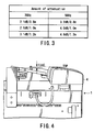
- FIG. 3 shows an example of amounts of attenuation in relation to the length of the cable.
- the amount of attenuation is 2.1 dB when the cable length is 0.8 m
- the amount of attenuation is 2.6 dB when the cable length is 1.0 m
- the amount of attenuation is 3.1 dB when the cable length is 1.2 m.
- the amount of attenuation is 3.2 dB when the cable length is 0.8 m
- the amount of attenuation is 4.0 dB when the cable length is 1.0 m
- the amount of attenuation is 4.8 dB when the cable length is 1.2 m.
- the control board 7 with the wireless LAN module 9 is provided on the rear side, the main antenna 5 and sub-antenna 6 are provided on the rear surface of the MFP 1 and the amount of attenuation due to the length of the connection cable can be minimized.
- the guideline for dosage of electromagnetic energy emitted by the wireless equipment i.e. 22 cm or more of distance between the wireless equipment and the operator
- the main antenna 5 and sub-antenna 6 are provided on the rear surface of the MFP 1, a predetermined distance can be secured from the operation panel 3 of the MFP 1, which the user operates directly.
- FIG. 4 shows an external appearance of an upper part of the MFP 1, as viewed from the rear side of MFP 1.
- the casing itself becomes an obstacle for radiation if the antennas are installed anywhere within the casing (in a direction toward the front surface of MFP 1).
- the condition for installation of the main antenna 5 and sub-antenna 6 in the height direction is optimized.
- the reversing automatic document feeder (RADF) 4 in the case where the reversing automatic document feeder (RADF) 4 is mounted, degradation in performance of the antennas can be prevented by installing them at a position higher than a position that is lower by 1 cm than the uppermost part of the RADF.
- a mechanism section 4a for feeding and reversing paper sheets is disposed on the left side of the MFP 1, as viewed from the front side (see FIG. 1). Since the mechanism section 4a itself is an obstacle to radiation, the main antenna 5 is disposed on a side opposite to the rear surface of the mechanism section 4a, whereby the radiation characteristics are improved (see FIGS. 1 and 2).
- the mechanism section 4a also becomes an obstacle to radiation, and the radiation characteristics are degraded.
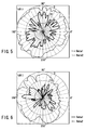
- FIG. 5 shows radiation characteristics of the main antenna 5.
- Data 1 indicates horizontal radiation characteristics
- Data 2 vertical radiation characteristics.
- the radiation characteristics of the main antenna 5 are illustrated such that front side of the MFP 1 is set at zero degree, the right side is set at 90 degrees, the rear side is set at 180 degrees, and the left side is set at 270 degrees. As is understood from FIG. 5, the characteristics in a range between about 270 degrees and about 315 degrees are degraded.
- the sub-antenna 6 is disposed at such a position as to be able to cover the range associated with the degradation in characteristics, thereby compensating the degraded radiation characteristics.
- FIG. 6 shows radiation characteristics of the sub-antenna 6.
- Data 1 indicates horizontal radiation characteristics
- Data 2 vertical radiation characteristics.
- the radiation characteristics of the sub-antenna 6 are illustrated such that front side of the MFP 1 is set at zero degree, the right side is set at 90 degrees, the rear side is set at 180 degrees, and the left side is set at 270 degrees.
- the degraded characteristics of the main antenna 5 in the range between about 270 degrees and about 315 degrees are compensated.
- the sub-antenna 6, as well as the main antenna 5, is provided. Thereby, degradation in radiation characteristics is suppressed.
- the fourth embodiment aims to optimize the condition for installation of antennas so as to minimize the interference due to the same-time communications using the Bluetooth function and wireless LAN function.
- FIG. 7 shows an external structure of the MFP 1, as viewed from above.
- the front side of the MFP 1 is indicated by an arrow in FIG. 7.
- the rear surface of the MFP 1 is provided with the main antenna 5, sub-antenna 6 and a Bluetooth antenna 10 that is used for the Bluetooth function.
- the interval between the antennas is set at 200 mm or more.
- the Bluetooth antenna 10 is disposed between the main antenna 5 and sub-antenna 6. Thereby, it becomes possible to suppress the adverse effect of interference due to same-time communications using the Bluetooth function and wireless LAN function.
Landscapes
- Engineering & Computer Science (AREA)
- Microelectronics & Electronic Packaging (AREA)
- Physics & Mathematics (AREA)
- General Physics & Mathematics (AREA)
- Multimedia (AREA)
- Signal Processing (AREA)
- Facsimiles In General (AREA)
- Support Of Aerials (AREA)
- Accessory Devices And Overall Control Thereof (AREA)
- Control Or Security For Electrophotography (AREA)
Abstract
Description
Claims (12)
- An image forming apparatus characterized by comprising:a main body (1) of the image forming apparatus;a wireless LAN module (9) that is provided inside a rear surface of the main body of the image forming apparatus;an antenna (5, 6) that is provided on the rear surface of the main body of the image forming apparatus; anda cable that connects the wireless LAN module (9) and the antenna (5, 6) with a shortest distance.
- The image forming apparatus according to claim 1, characterized in that the wireless LAN module is provided on a control board (7) that is disposed inside the rear surface of the main body of the image forming apparatus.
- The image forming apparatus according to claim 1, characterized in that the antenna comprises a main antenna (5) and a sub-antenna (6).
- The image forming apparatus according to claim 1, characterized in that the antenna comprises a dual-band antenna.
- An image forming apparatus with an automatic document feeder, characterized by comprising:a wireless LAN module (9) that is provided inside a rear surface of a main body of the image forming apparatus; andan uppermost part of an antenna (5, 6) that is connected to the wireless LAN module and is provided on the rear surface of the main body of the image forming apparatus, the uppermost part of the antenna being located at a position higher than a predetermined position relative to an uppermost part of the automatic document feeder (4).
- The image forming apparatus according to claim 5, characterized in that the uppermost part of the antenna is located at a position higher than a position that is lower by 1 cm than the uppermost part of the automatic document feeder.
- An image forming apparatus with an automatic document feeder, characterized by comprising:a wireless LAN module (9) that is provided inside a rear surface of a main body of the image forming apparatus;a main antenna (5) that is connected to the wireless LAN module and is provided on the rear surface of the main body of the image forming apparatus, the main antenna being located at a position where optimal radiation characteristics are obtained in consideration of the presence of the automatic document feeder that is an obstacle to a front side of the image forming apparatus; anda sub-antenna (6) that is connected to the wireless LAN module and is provided on the rear surface of the main body of the image forming apparatus.
- The image forming apparatus according to claim 7, characterized in that an uppermost part of the main antenna is provided on that part of the rear surface of the image forming apparatus, which corresponds to a right side of the front surface of the image forming apparatus, at a position that is lower by 1 cm than an uppermost part of the automatic document feeder.
- The image forming apparatus according to claim 7, characterized in that the sub-antenna (6) is provided at such a position as to compensate a degraded portion of radiation characteristics of the main antenna (5).
- The image forming apparatus according to claim 7, characterized in that an uppermost part of the sub-antenna (6) is provided on that part of the rear surface of the image forming apparatus, which corresponds to a left side of the front surface of the image forming apparatus, at a position that is lower by 1 cm than an uppermost part of the automatic document feeder (4).
- The image forming apparatus according to claim 7, characterized by further comprising an antenna (5) for Bluetooth, which is disposed between the main antenna and the sub-antenna (6), with a predetermined distance from the main antenna (5) and a predetermined distance from the sub-antenna (6).
- The image forming apparatus according to claim 11, characterized in that the antenna for Bluetooth is disposed with a distance of 200 mm or more from the main antenna (5) and with a distance of 200 mm or more from the sub-antenna (6).
Applications Claiming Priority (2)
| Application Number | Priority Date | Filing Date | Title |
|---|---|---|---|
| US10/805,307 US20050206962A1 (en) | 2004-03-22 | 2004-03-22 | Image forming apparatus |
| US805307 | 2004-03-22 |
Publications (2)
| Publication Number | Publication Date |
|---|---|
| EP1580623A2 true EP1580623A2 (en) | 2005-09-28 |
| EP1580623A3 EP1580623A3 (en) | 2010-06-02 |
Family
ID=34862014
Family Applications (1)
| Application Number | Title | Priority Date | Filing Date |
|---|---|---|---|
| EP04026017A Withdrawn EP1580623A3 (en) | 2004-03-22 | 2004-11-03 | Image forming apparatus having an antenna for wireless communication |
Country Status (4)
| Country | Link |
|---|---|
| US (1) | US20050206962A1 (en) |
| EP (1) | EP1580623A3 (en) |
| JP (1) | JP2005278172A (en) |
| CN (2) | CN1330500C (en) |
Families Citing this family (5)
| Publication number | Priority date | Publication date | Assignee | Title |
|---|---|---|---|---|
| JP5707425B2 (en) * | 2013-01-07 | 2015-04-30 | 株式会社東芝 | Communications system |
| JP6206166B2 (en) * | 2013-12-24 | 2017-10-04 | ブラザー工業株式会社 | Image forming apparatus |
| JP6813970B2 (en) * | 2016-07-04 | 2021-01-13 | キヤノン株式会社 | Information processing device, its control method, and program |
| JP6911384B2 (en) * | 2017-02-28 | 2021-07-28 | コニカミノルタ株式会社 | Image processing device |
| JP7764714B2 (en) * | 2021-09-22 | 2025-11-06 | 富士フイルムビジネスイノベーション株式会社 | Information processing device |
Family Cites Families (12)
| Publication number | Priority date | Publication date | Assignee | Title |
|---|---|---|---|---|
| US5117505A (en) * | 1990-02-22 | 1992-05-26 | American Nucleonics Corporation | Interference cancellation system having noise reduction features and method |
| JP3352914B2 (en) * | 1997-06-24 | 2002-12-03 | シャープ株式会社 | Color image forming equipment |
| US6134105A (en) * | 1998-01-06 | 2000-10-17 | Lueker; Mark David | Portable command center |
| US6069587A (en) * | 1998-05-15 | 2000-05-30 | Hughes Electronics Corporation | Multiband millimeterwave reconfigurable antenna using RF mem switches |
| US6049314A (en) * | 1998-11-17 | 2000-04-11 | Xertex Technologies, Inc. | Wide band antenna having unitary radiator/ground plane |
| JP2002073210A (en) * | 2000-08-31 | 2002-03-12 | Toshiba Corp | Portable information equipment with built-in wireless communication antenna |
| JP2002151928A (en) * | 2000-11-08 | 2002-05-24 | Toshiba Corp | Antennas and electronic devices incorporating antennas |
| US6448933B1 (en) * | 2001-04-11 | 2002-09-10 | Tyco Electronics Logisitics Ag | Polarization and spatial diversity antenna assembly for wireless communication devices |
| JP2002341072A (en) * | 2001-05-16 | 2002-11-27 | Canon Inc | Time correction method |
| JP4576071B2 (en) * | 2001-07-02 | 2010-11-04 | パナソニックシステムネットワークス株式会社 | Network image processing apparatus, monitoring apparatus and method thereof |
| US6944428B2 (en) * | 2001-08-06 | 2005-09-13 | Kabushiki Kaisha Toshiba | Image information input/output device and control system for the same using mobile device |
| JP4017434B2 (en) * | 2002-04-12 | 2007-12-05 | キヤノンファインテック株式会社 | Recording device and recording system |
-
2004
- 2004-03-22 US US10/805,307 patent/US20050206962A1/en not_active Abandoned
- 2004-11-03 EP EP04026017A patent/EP1580623A3/en not_active Withdrawn
- 2004-11-30 CN CNB2004100978699A patent/CN1330500C/en not_active Expired - Fee Related
- 2004-11-30 CN CNA200710112027XA patent/CN101105683A/en active Pending
-
2005
- 2005-03-17 JP JP2005076562A patent/JP2005278172A/en active Pending
Also Published As
| Publication number | Publication date |
|---|---|
| CN101105683A (en) | 2008-01-16 |
| CN1330500C (en) | 2007-08-08 |
| US20050206962A1 (en) | 2005-09-22 |
| JP2005278172A (en) | 2005-10-06 |
| CN1672947A (en) | 2005-09-28 |
| EP1580623A3 (en) | 2010-06-02 |
Similar Documents
| Publication | Publication Date | Title |
|---|---|---|
| EP2369417B1 (en) | Multifunction apparatus | |
| US9131086B2 (en) | Image forming apparatus | |
| US9204001B2 (en) | Image reading device and multifunction apparatus provided with the same | |
| US10177436B2 (en) | Image forming apparatus having wireless communication device | |
| JP6027954B2 (en) | Image forming apparatus | |
| JP5836538B2 (en) | Image forming apparatus | |
| US11300917B2 (en) | Image forming apparatus | |
| CN102686079B (en) | Holder for holding cable noise suppressor and image forming system incorporating same | |
| US20050206962A1 (en) | Image forming apparatus | |
| US11588244B2 (en) | Antenna structure | |
| JP2006056017A (en) | Image forming apparatus | |
| JP2017227729A (en) | Image forming apparatus | |
| CN100417171C (en) | image forming equipment | |
| US11485592B2 (en) | Sheet feeding apparatus including an electric circuit board | |
| JP2024042831A (en) | Image reading device and image forming device | |
| JP5803297B2 (en) | Compound machine | |
| US20120134116A1 (en) | Image forming apparatus | |
| JP2008304867A (en) | Image forming apparatus | |
| KR20050032728A (en) | Multi-functional apparatus | |
| JP7722091B2 (en) | multifunction device | |
| US7355834B2 (en) | Cover unit of a substrate for an image forming apparatus and method | |
| JP5157152B2 (en) | Electronics | |
| US20240022671A1 (en) | Image forming apparatus | |
| JP2021052267A (en) | Information processing device and image forming apparatus | |
| JP2003271064A (en) | Information display device and image processing apparatus provided with the device |
Legal Events
| Date | Code | Title | Description |
|---|---|---|---|
| PUAI | Public reference made under article 153(3) epc to a published international application that has entered the european phase |
Free format text: ORIGINAL CODE: 0009012 |
|
| 17P | Request for examination filed |
Effective date: 20041103 |
|
| AK | Designated contracting states |
Kind code of ref document: A2 Designated state(s): AT BE BG CH CY CZ DE DK EE ES FI FR GB GR HU IE IS IT LI LU MC NL PL PT RO SE SI SK TR |
|
| AX | Request for extension of the european patent |
Extension state: AL HR LT LV MK YU |
|
| PUAL | Search report despatched |
Free format text: ORIGINAL CODE: 0009013 |
|
| AK | Designated contracting states |
Kind code of ref document: A3 Designated state(s): AT BE BG CH CY CZ DE DK EE ES FI FR GB GR HU IE IS IT LI LU MC NL PL PT RO SE SI SK TR |
|
| AX | Request for extension of the european patent |
Extension state: AL HR LT LV MK YU |
|
| RIC1 | Information provided on ipc code assigned before grant |
Ipc: H04N 1/00 20060101ALI20100429BHEP Ipc: H04L 12/28 20060101ALI20100429BHEP Ipc: G06F 3/12 20060101ALI20100429BHEP Ipc: G03G 21/18 20060101AFI20050705BHEP |
|
| AKX | Designation fees paid |
Designated state(s): DE FR GB |
|
| STAA | Information on the status of an ep patent application or granted ep patent |
Free format text: STATUS: THE APPLICATION HAS BEEN WITHDRAWN |
|
| 18W | Application withdrawn |
Effective date: 20120719 |