EP1580565A2 - Flexible test cable - Google Patents
Flexible test cable Download PDFInfo
- Publication number
- EP1580565A2 EP1580565A2 EP05251464A EP05251464A EP1580565A2 EP 1580565 A2 EP1580565 A2 EP 1580565A2 EP 05251464 A EP05251464 A EP 05251464A EP 05251464 A EP05251464 A EP 05251464A EP 1580565 A2 EP1580565 A2 EP 1580565A2
- Authority
- EP
- European Patent Office
- Prior art keywords
- dielectric
- cable according
- center conductor
- conductive sleeve
- cable
- Prior art date
- Legal status (The legal status is an assumption and is not a legal conclusion. Google has not performed a legal analysis and makes no representation as to the accuracy of the status listed.)
- Granted
Links
Images

Classifications
-
- H—ELECTRICITY
- H01—ELECTRIC ELEMENTS
- H01B—CABLES; CONDUCTORS; INSULATORS; SELECTION OF MATERIALS FOR THEIR CONDUCTIVE, INSULATING OR DIELECTRIC PROPERTIES
- H01B7/00—Insulated conductors or cables characterised by their form
- H01B7/04—Flexible cables, conductors, or cords, e.g. trailing cables
-
- G—PHYSICS
- G01—MEASURING; TESTING
- G01R—MEASURING ELECTRIC VARIABLES; MEASURING MAGNETIC VARIABLES
- G01R29/00—Arrangements for measuring or indicating electric quantities not covered by groups G01R19/00 - G01R27/00
- G01R29/08—Measuring electromagnetic field characteristics
- G01R29/0807—Measuring electromagnetic field characteristics characterised by the application
- G01R29/0814—Field measurements related to measuring influence on or from apparatus, components or humans, e.g. in ESD, EMI, EMC, EMP testing, measuring radiation leakage; detecting presence of micro- or radiowave emitters; dosimetry; testing shielding; measurements related to lightning
-
- G—PHYSICS
- G01—MEASURING; TESTING
- G01R—MEASURING ELECTRIC VARIABLES; MEASURING MAGNETIC VARIABLES
- G01R1/00—Details of instruments or arrangements of the types included in groups G01R5/00 - G01R13/00 and G01R31/00
- G01R1/20—Modifications of basic electric elements for use in electric measuring instruments; Structural combinations of such elements with such instruments
- G01R1/24—Transmission-line, e.g. waveguide, measuring sections, e.g. slotted section
-
- H—ELECTRICITY
- H01—ELECTRIC ELEMENTS
- H01B—CABLES; CONDUCTORS; INSULATORS; SELECTION OF MATERIALS FOR THEIR CONDUCTIVE, INSULATING OR DIELECTRIC PROPERTIES
- H01B11/00—Communication cables or conductors
- H01B11/18—Coaxial cables; Analogous cables having more than one inner conductor within a common outer conductor
- H01B11/1834—Construction of the insulation between the conductors
- H01B11/1856—Discontinuous insulation
Definitions
- This disclosure relates generally to anechoic electromagnetic field test chambers, and more particularly to cables used in such test chambers for testing electronic devices.
- Anechoic chambers are used to test radio-frequency (RF) emissions of electronic devices such as radiotelephones, pagers, and cordless telephones. These chambers include a shielded enclosure and absorber material, positioners and mounts for the device under test (DUT), and cabling. Each of these elements must be precision-implemented to produce a high quality anechoic chamber. It is desirable that the elements be re-usable and reconfigurable to enable testing of a range of devices in a variety of environments. Occasionally, a human model (sometimes called a "phantom”) is added to the environment to approximate the effect of a human being on a DUT's RF emissions.
- a human model sometimes called a "phantom"
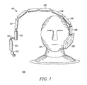
- FIG. 1 shows a flexible test cable according to a preferred embodiment in a radio-frequency (RF) testing environment.
- RF radio-frequency
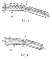
- FIG. 2 shows rigid cable segments of the flexible test cable shown in FIG. 1 according to a first embodiment.
- FIG. 3 shows rigid cable segments of the flexible test cable shown in FIG. 1 according to a second embodiment.
- FIG. 4 shows a flexible test cable according to the preferred embodiment in another radio-frequency (RF) testing environment.
- RF radio-frequency
- a flexible test cable has a center conductor, a conductive sleeve with an effective electrical length equal to an odd quarter wavelength of a frequency of interest, a dielectric spacer located inside the conductive sleeve for preventing a portion of the center conductor from electrically coupling to the conductive sleeve, and a dielectric joint for maintaining a portion of the center conductor in the middle of an end of the conductive sleeve.
- the conductive sleeve can have a variety of cross-sectional shapes.
- the dielectric spacer can be formed in a variety of shapes from rigid or compressible dielectric materials.
- the dielectric joint can be formed in a variety of shapes from rigid or compressible dielectric materials. Using the dielectric joint to link together multiple conductive sleeves results in a flexible test cable with electrical transparency at the frequency of interest.
- FIG. 1 shows a flexible test cable 150 according to a preferred embodiment in a radio-frequency (RF) testing environment 100.
- the RF testing environment 100 includes a phantom head 110 and a device under test (DUT) 190 mounted near an ear portion of the phantom head 110.
- DUT device under test
- the enclosure of the environment is shielded, and pyramidal absorber material is placed on all inner surfaces of the enclosure in accordance with general RF testing procedures.
- the flexible test cable 150 provides power, control, or other test signals to the DUT 190 during testing.
- test cables for this RF testing environment 100 must go from a test engineer bench, which is usually outside of the anechoic chamber, to the DUT 190, which is generally toward the center of the anechoic chamber, there is no place to electrically hide these test cables when measuring the RF radiation pattern of an omni-directional antenna.
- omni-directional antennas are common for radiotelephones, thus the DUT 190 is shown as a radiotelephone.
- the flexible test cable 150 can be used for other types of DUTs and other types of antennas.
- the flexible test cable 150 includes at least one rigid cable segment 158.
- the rigid cable segments 158 have an effective electrical length of odd quarter wavelengths (1 ⁇ 4 ⁇ , 3 ⁇ 4 ⁇ , etc.) of the frequency of interest.
- the rigid cable segments 158 shown are 1 ⁇ 4 ⁇ ; however, other odd quarter wavelengths provide similar RF invisibility and may be used as appropriate depending on factors such as the desire for cable flexibility, the desire for cable strength, the test environment, and the frequency of interest.
- a final rigid cable segment 159 at the end of the flexible test cable 150 couples to the DUT 190 chassis at a point of low electromagnetic fields.
- an initial rigid cable segment 157 is coupled to a sleeve 156 with an integral right-angle connector.
- a connector pair 155 couples the sleeve 156 to another sleeve 154 on a rigid test cable.
- Another connector 152 allows for electrical connection of the flexible test cable 150 to another cable, such as another rigid test cable.
- Different connector configurations can be substituted for the ones shown here in order to accommodate other testing environments.
- This flexible test cable 150 addresses a number of issues.
- the various connectors 152, 155 and sleeves 154, 156 at the beginning of the flexible test cable 150 provide strength and stability to the flexible test cable 150 such that the cable 150 can couple to the DUT 190 without overly taxing the DUT mount (not shown).
- the test cable 150 is flexible enough to be applied to a variety of DUT types in a variety of testing environments. Previously, different DUTs usually needed different test cables due to the different DUT sizes -- even when the different DUTs all had the same frequency of interest. Also previously, even with the same DUT, sometimes different cables were needed for different testing configurations.
- each rigid cable segment 158 has a high impedance end that provides decoupling of the flexible test cable 150 from the DUT 190.
- FIG. 2 shows rigid cable segments 200 of the flexible test cable 180 shown in FIG. 1 according to a first embodiment.
- a center conductor 210 is surrounded by spherical dielectric spacers 230 that provide appropriate spacing of the center conductor 210 from an odd quarter wavelength choke sleeve 240.
- the center conductor 210 can be either a single wire or multiple wires, depending on the implementation of the flexible test cable 150 shown in FIG. 1. A common implementation of the flexible test cable 150 would be for a coaxial cable. Alternately, the center conductor 210 may include a braid of wires that enclose and shield a single wire or group of wires. The center conductor 210 passes through an odd quarter wavelength choke sleeve 240.
- the sleeve 240 is constructed of a conductive material and has a bushing 225 on one end to electrically couple the center conductor 210 to the sleeve 240.
- the other end 227 of the sleeve 240 is open. Because the sleeve 240 is an odd quarter wavelength, the open end 227 has high impedance, which allows for decoupling of the RF signals in the flexible test cable 150 from the DUT 190 shown in FIG. 1.
- the sleeve is cylindrical in shape with a circular cross-section. Alternate shapes, however, are available such as a sleeve with a square cross-section, an oval cross-section, or a hexagonal cross-section.
- one or more dielectric spacers 230 surround a length of the center conductor 210.
- the dielectric spacers 230 are configured as spheres with a diameter smaller than the diameter of the sleeve 240, and an air gap 250 results between at least a portion of the dielectric spacers 230 and the inner surface of the sleeve 240.
- the center conductor 210 passes through a diameter of each sphere and is protected both electrically and physically by the dielectric spacer 230.
- the dielectric sphere construction allows a portion of the center conductor 210 to bend and flex inside the sleeve 240 without electrically coupling to the sleeve 240 and without significantly straining the conductor 210.
- dielectric spacers 230 are shown continuously enclosing the center conductor 210, such continuous enclosure is not necessary for all applications. In other words, there may be gaps between consecutive dielectric spacers 230. Alternate configurations for the dielectric spacers 230 include ovoid and disk.
- the dielectric spacers can be constructed from a rigid dielectric material or a soft, compressible dielectric material such as open cell foam.
- a dielectric joint 220 is located near the open end 227 of the sleeve 240 to maintain the position of the center conductor 210 in the middle of the open end 227 of the choke sleeve 240.
- the dielectric joint 220 shown is spherical in shape, which permits a large range of movement of the rigid cable segments 158 relative to each other (shown in FIG. 1) without allowing too much strain on the center conductor 210.
- Alternate shapes for the dielectric joints 220 include hemispherical, ovoid, and disk shapes constructed from rigid or compressible dielectric materials.
- the dielectric joint on the final rigid cable segment 159 (shown in FIG. 1) can be custom-designed to conform to the electrical connection to the DUT 190 (shown in FIG. 1).
- a hemispherical dielectric cover 226 is included on the bushing 225.
- Other cover 226 configurations are available, including ovoid and square shapes formed from rigid or compressible dielectric materials. Omitting the cover 226 is also a possibility with a potential lessening of flexibility or strength between rigid cable segments.
- the combination of spherical dielectric spacers 230 and spherical dielectric joints 220 provides flexibility to the entire test cable 150 (shown in FIG. 1) as well as strength.
- the flexible test cable 150 (shown in FIG. 1) can be positioned over, around, or under DUT mounts, positioners, phantoms, and other elements of the testing environment. Additionally, the flexibility and strength of the test cable 150 allows reuse of the test cable for a number of DUTs in a number of testing environments.
- FIG. 3 shows rigid cable segments 300 of the flexible test cable 180 shown in FIG. 1 according to a second embodiment.
- a center conductor 310 is surrounded by a dielectric spacer 330 fashioned as a solid dielectric tube that is located inside an odd quarter wavelength choke sleeve 340.
- the sleeve is cylindrical in shape with a circular cross-section. Alternate shapes, however, are available such as a sleeve with a square cross-section, an oval cross-section, or a hexagonal cross-section.
- the center conductor 310 can be either a single wire or multiple wires, depending on the implementation of the flexible test cable 150 shown in FIG. 1. A common implementation of the flexible test cable 150 would be for a coaxial cable. Alternately, the center conductor 310 may include a braid of wires that enclose and shield a single wire or group of wires. The center conductor 310 passes through an odd quarter wavelength choke sleeve 340.
- the sleeve 340 is constructed of a conductive material and has a bushing 325 on one end to electrically couple the center conductor 310 to the sleeve 340.
- the other end 327 of the sleeve 340 is open. Because the sleeve 340 is an odd quarter wavelength, the open end 327 has high impedance, which allows for decoupling of the RF signals in the flexible test cable 150 from the DUT 190 shown in FIG. 1.
- one or more dielectric spacers 330 surround a length of the center conductor 310.
- the center conductor 310 is loosely positioned along a longitudinal axis of the dielectric spacer 330.
- a single dielectric spacer 330 is configured as a solid dielectric tube with an outer circumference that contacts the inner surface of the sleeve 340 and an inner diameter greater than the diameter of the center conductor 310.
- an air gap 350 results between at least a portion of the dielectric spacer 330 and the center conductor 310.
- the dielectric tube construction with tubular air gap allows a portion of the center conductor 310 to bend and flex inside the sleeve 340 without electrically coupling to the sleeve 340 and without significantly straining the conductor 310.
- the dielectric spacers 330 are shown continuously enclosing the center conductor 310 within a sleeve 340, such continuous enclosure is not necessary for all applications.
- the dielectric spacer 330 can be constructed from one tube having the length of the sleeve 340 or several contiguous (but not necessarily touching) tubes.
- the dielectric spacer 330 can be constructed from rigid dielectric material or soft, compressible dielectric material such as open cell foam.
- a dielectric joint 320 is located near the open end 327 of the sleeve 340 to maintain the position of the center conductor 310 in the middle of the open end 327 of the choke sleeve 340.
- the dielectric joint 320 shown is spherical in shape, which permits a large range of movement of the rigid cable segments 158 relative to each other (shown in FIG. 1) without allowing too much strain on the center conductor 310.
- Alternate shapes for the dielectric joints 320 include hemispherical, ovoid, and disk constructed from rigid or compressible dielectric materials.
- the dielectric joint on the final rigid cable segment 159 (shown in FIG. 1) can be custom-designed to conform to the electrical connection to the DUT 190 (shown in FIG. 1).
- FIG. 4 shows a flexible test cable 450 according to the preferred embodiment in another radio-frequency (RF) testing environment 400.
- This RF testing environment 400 includes a phantom head 410 mounted on a support 480 and a device under test (DUT) 490 mounted near an ear portion of the phantom head 410. Because the DUT 490 is mounted on a support 480, a rigid test cable 460 is used in combination with a flexible test cable 450 to bring power, control, or any other test signals to the DUT 490 during testing.
- the enclosure of the environment is shielded, and pyramidal absorber material is placed on all inner surfaces of the enclosure in accordance with general RF testing procedures.
- test cables for this RF testing environment 400 must go from a test engineer bench, which is usually outside of the anechoic chamber, to the DUT 490, which is generally toward the center of the anechoic chamber, there is no place to electrically hide these test cables when measuring the RF radiation pattern of an omni-directional antenna.
- omni-directional antennas are common for radiotelephones, thus the DUT 490 is shown as a radiotelephone.
- the flexible test cable 450 can be used for other types of DUTs and other types of antennas.
- the rigid test cable 460 is an odd quarter wavelength (1 ⁇ 4 ⁇ , 3 ⁇ 4 ⁇ , etc.) of the frequency of interest to provide decoupling of the rigid test cable 460 from the flexible test cable 450.
- a rigid test cable 460 which is easier and less costly to manufacture
- a flexible test cable 450 provides cabling that is nearly invisible at a frequency of interest in a variety of testing environments.
- a single flexible test cable can provide power, control, or other test signals in a variety of testing environments at that frequency of interest.
- the various dielectric spacers, air gaps, and dielectric joints allow manipulation of the flexible test cable with acceptable strain on the center conductor.
- the conductive sleeves, dielectric spacers, and dielectric joints also maintain the electrical choke configuration of the rigid cable segments of the flexible test cable during and after manipulation of the flexible test cable.
- relational terms such as first and second, top and bottom, and the like, if any, are used solely to distinguish one from another entity, item, or action without necessarily requiring or implying any actual such relationship or order between such entities, items or actions.
Landscapes
- Physics & Mathematics (AREA)
- General Physics & Mathematics (AREA)
- Electromagnetism (AREA)
- Communication Cables (AREA)
- Insulated Conductors (AREA)
- Connections Effected By Soldering, Adhesion, Or Permanent Deformation (AREA)
- Measuring Leads Or Probes (AREA)
- Coupling Device And Connection With Printed Circuit (AREA)
- Multi-Conductor Connections (AREA)
Abstract
Description
Claims (25)
- A cable comprising:a center conductor;a conductive sleeve having a first end and a second end and an effective electrical length equal to an odd quarter wavelength of a frequency of interest, surrounding a portion of the center conductor, with the first end physically and electrically coupled to the center conductor;a dielectric spacer, located inside the conductive sleeve, for preventing another portion of the center conductor from physically and electrically coupling to the conductive sleeve; anda dielectric joint, coupled to the second end of the conductive sleeve, for positioning a portion of the center conductor in a middle of the second end.
- A cable according to claim 1 wherein the center conductor includes a single wire.
- A cable according to claim 1 wherein the center conductor includes multiple wires.
- A cable according to claim 1 wherein the dielectric spacer is constructed from a rigid dielectric material.
- A cable according to claim 1 wherein the dielectric spacer is constructed from a compressible dielectric material.
- A cable according to claim 1 wherein the dielectric spacer comprises a spherical dielectric element.
- A cable according to claim 6 wherein a diameter of the spherical dielectric element is shorter than a diameter of the conductive sleeve.
- A cable according to claim 6 wherein the center conductor is located inside the dielectric spacer along a diameter of the dielectric spacer.
- A cable according to claim 6 wherein the dielectric spacer comprises multiple spherical dielectric elements.
- A cable according to claim 1 wherein the dielectric spacer comprises a tubular solid dielectric element with an outer diameter and an inner diameter.
- A cable according to claim 10 wherein the center conductor is located inside the dielectric spacer along a longitudinal axis of the tubular solid dielectric element.
- A cable according to claim 10 wherein the outer diameter of the tubular solid dielectric element is approximately a diameter of the conductive sleeve and the inner diameter of the tubular solid dielectric element is larger than a diameter of the center conductor.
- A cable according to claim 10 wherein the dielectric spacer further comprises a tubular air dielectric element inside the tubular solid dielectric element.
- A cable according to claim 1 wherein the dielectric joint comprises a spherical dielectric element.
- A cable according to claim 14 wherein a diameter of the spherical dielectric element is approximately equal to a diameter of the conductive sleeve.
- A cable according to claim 14 wherein the center conductor is located inside the dielectric joint along a diameter of the dielectric joint.
- A cable according to claim 1 wherein the first end comprises a conductive bushing
- A cable according to claim 17 wherein the first end further comprises a hemispherical dielectric cover.
- A cable according to claim 1 wherein the conductive sleeve is cylindrical in shape.
- A cable according to claim 1 wherein the dielectric joint is constructed from a rigid dielectric material.
- A cable according to claim 1 wherein the dielectric joint is constructed from a compressible dielectric material.
- A cable comprising:a first rigid segment having an effective electrical length equal to an odd quarter wavelength of a frequency of interest;a flexible joint, coupled to one end of the first rigid segment;a second rigid segment having an effective electrical length equal to an odd quarter wavelength of the frequency of interest, coupled to the flexible joint; anda linear conductor, located within the first rigid segment, the flexible joint, and the second rigid segment.
- A cable according to claim 22 further comprising:a first dielectric spacer, located inside the first rigid segment; anda second dielectric spacer, located inside the second rigid segment.
- A cable according to claim 22 further wherein the first rigid segment comprises a conductive sleeve with one end electrically coupled to the linear conductor.
- A cable according to claim 24 wherein the flexible joint comprises a dielectric element that maintains a portion of the linear conductor in a middle of the conductive sleeve.
Priority Applications (1)
| Application Number | Priority Date | Filing Date | Title |
|---|---|---|---|
| EP09014772A EP2161585A3 (en) | 2004-03-22 | 2005-03-10 | Flexible test cable |
Applications Claiming Priority (2)
| Application Number | Priority Date | Filing Date | Title |
|---|---|---|---|
| US806019 | 2004-03-22 | ||
| US10/806,019 US6927332B1 (en) | 2004-03-22 | 2004-03-22 | Flexible test cable |
Related Child Applications (1)
| Application Number | Title | Priority Date | Filing Date |
|---|---|---|---|
| EP09014772A Division-Into EP2161585A3 (en) | 2004-03-22 | 2005-03-10 | Flexible test cable |
Publications (3)
| Publication Number | Publication Date |
|---|---|
| EP1580565A2 true EP1580565A2 (en) | 2005-09-28 |
| EP1580565A3 EP1580565A3 (en) | 2005-11-16 |
| EP1580565B1 EP1580565B1 (en) | 2014-04-30 |
Family
ID=34808688
Family Applications (2)
| Application Number | Title | Priority Date | Filing Date |
|---|---|---|---|
| EP09014772A Withdrawn EP2161585A3 (en) | 2004-03-22 | 2005-03-10 | Flexible test cable |
| EP05251464.3A Expired - Lifetime EP1580565B1 (en) | 2004-03-22 | 2005-03-10 | Flexible test cable |
Family Applications Before (1)
| Application Number | Title | Priority Date | Filing Date |
|---|---|---|---|
| EP09014772A Withdrawn EP2161585A3 (en) | 2004-03-22 | 2005-03-10 | Flexible test cable |
Country Status (6)
| Country | Link |
|---|---|
| US (1) | US6927332B1 (en) |
| EP (2) | EP2161585A3 (en) |
| JP (2) | JP5220986B2 (en) |
| KR (1) | KR100631448B1 (en) |
| CN (2) | CN100357747C (en) |
| TW (1) | TWI363358B (en) |
Families Citing this family (7)
| Publication number | Priority date | Publication date | Assignee | Title |
|---|---|---|---|---|
| US6927332B1 (en) * | 2004-03-22 | 2005-08-09 | Motorola, Inc. | Flexible test cable |
| US20060254803A1 (en) * | 2005-05-26 | 2006-11-16 | Dorffler Albertina H | Ornamental computer network cables |
| US20090069804A1 (en) * | 2007-09-12 | 2009-03-12 | Jensen Jeffrey L | Apparatus for efficient power delivery |
| WO2014063042A1 (en) | 2012-10-19 | 2014-04-24 | Milwaukee Electric Tool Corporation | Visual inspection device |
| US8941532B2 (en) * | 2012-12-06 | 2015-01-27 | Rosemount Tank Radar Ab | Probe spacing element |
| WO2016045840A1 (en) * | 2014-09-22 | 2016-03-31 | Huber+Suhner Ag | Passive intermodulation test lead |
| EP3760984B1 (en) * | 2019-07-03 | 2023-08-30 | Rosemount Tank Radar AB | Transmission line probe |
Family Cites Families (23)
| Publication number | Priority date | Publication date | Assignee | Title |
|---|---|---|---|---|
| US1911470A (en) * | 1929-03-09 | 1933-05-30 | Bendix Brake Co | Flexible cable |
| US2018353A (en) * | 1930-11-21 | 1935-10-22 | Telefunken Gmbh | Transmission line |
| US2495867A (en) * | 1948-01-14 | 1950-01-31 | Petcar Res Corp | Method of manufacturing fire detector and like elements |
| US2587916A (en) * | 1949-09-14 | 1952-03-04 | Specialties Dev Corp | Heat detecting cable |
| US2566335A (en) * | 1949-11-17 | 1951-09-04 | Specialties Dev Corp | Heat or flame detecting element and assembly |
| US3105287A (en) * | 1957-05-08 | 1963-10-01 | Rea Magnet Wire Company Inc | Insulated wire particularly for coils and the manufacture thereof |
| US3106599A (en) * | 1961-11-10 | 1963-10-08 | Technical Appliance Corp | Expansible connector for rigid coaxial transmission line |
| US4029891A (en) * | 1976-01-22 | 1977-06-14 | General Electric Company | Particle trapping sheath coupling for enclosed electric bus apparatus |
| FR2435787A1 (en) * | 1978-09-08 | 1980-04-04 | Commissariat Energie Atomique | ANTIMICROPHONIC COAXIAL CABLE THAT CAN OPERATE AT HIGH TEMPERATURE |
| JPS57111904A (en) * | 1980-12-27 | 1982-07-12 | Horiba Ltd | Flexible cable |
| JPS6436917U (en) * | 1987-08-31 | 1989-03-06 | ||
| US5397994A (en) * | 1993-12-28 | 1995-03-14 | Alkon Corporation | Moisture measurement gauge for particulates including a transmission line forming part of a resonant circuit |
| US5455548A (en) * | 1994-02-28 | 1995-10-03 | General Signal Corporation | Broadband rigid coaxial transmission line |
| DE19540807C1 (en) * | 1995-11-02 | 1997-04-17 | Mayer Textilmaschf | Flexible electrical cable and electrical connection consisting of this cable |
| JP2866054B2 (en) * | 1996-05-28 | 1999-03-08 | 宇呂電子工業株式会社 | Line radiation prevention element |
| FR2753301B1 (en) * | 1996-09-09 | 1998-10-09 | Alcatel Cable | DEVICE FOR TRANSPORTING AN ELECTRIC SIGNAL PROTECTED AGAINST ELECTROMAGNETIC DISTURBANCES |
| GB9912627D0 (en) * | 1999-05-28 | 1999-07-28 | Gyrus Medical Ltd | An electrosurgical instrument |
| JP2001077607A (en) * | 1999-09-06 | 2001-03-23 | Sumitomo Heavy Ind Ltd | High frequency transmission line |
| IT1317520B1 (en) * | 2000-05-11 | 2003-07-09 | Traversa Ezio Plastici | MODULAR AND ADJUSTABLE ELEMENTS FOR CABLE DUCTS. |
| WO2002007265A1 (en) * | 2000-07-13 | 2002-01-24 | Rika Electronics International, Inc. | Contact apparatus particularly useful with test equipment |
| US7026544B2 (en) * | 2001-12-20 | 2006-04-11 | Koninklijke Philips Electronics N.V. | RF system for an MRI apparatus, provided with bead-shaped spacers |
| CA2487140C (en) | 2002-05-29 | 2011-09-20 | Surgi-Vision, Inc. | Magnetic resonance probes |
| US6927332B1 (en) * | 2004-03-22 | 2005-08-09 | Motorola, Inc. | Flexible test cable |
-
2004
- 2004-03-22 US US10/806,019 patent/US6927332B1/en not_active Expired - Lifetime
-
2005
- 2005-03-10 EP EP09014772A patent/EP2161585A3/en not_active Withdrawn
- 2005-03-10 EP EP05251464.3A patent/EP1580565B1/en not_active Expired - Lifetime
- 2005-03-11 TW TW094107396A patent/TWI363358B/en not_active IP Right Cessation
- 2005-03-18 JP JP2005078935A patent/JP5220986B2/en not_active Expired - Fee Related
- 2005-03-21 KR KR1020050022999A patent/KR100631448B1/en not_active Expired - Fee Related
- 2005-03-22 CN CNB2005100559628A patent/CN100357747C/en not_active Expired - Fee Related
- 2005-03-22 CN CN2007101081379A patent/CN101067636B/en not_active Expired - Fee Related
-
2012
- 2012-05-30 JP JP2012122935A patent/JP5722828B2/en not_active Expired - Fee Related
Also Published As
| Publication number | Publication date |
|---|---|
| JP2012199245A (en) | 2012-10-18 |
| KR100631448B1 (en) | 2006-10-11 |
| EP2161585A2 (en) | 2010-03-10 |
| KR20060044461A (en) | 2006-05-16 |
| TW200603178A (en) | 2006-01-16 |
| JP5722828B2 (en) | 2015-05-27 |
| CN101067636B (en) | 2010-08-18 |
| EP1580565A3 (en) | 2005-11-16 |
| CN100357747C (en) | 2007-12-26 |
| EP1580565B1 (en) | 2014-04-30 |
| CN1673759A (en) | 2005-09-28 |
| JP5220986B2 (en) | 2013-06-26 |
| CN101067636A (en) | 2007-11-07 |
| TWI363358B (en) | 2012-05-01 |
| JP2005276829A (en) | 2005-10-06 |
| US6927332B1 (en) | 2005-08-09 |
| EP2161585A3 (en) | 2010-11-10 |
Similar Documents
| Publication | Publication Date | Title |
|---|---|---|
| JP5722828B2 (en) | Flexible test cable | |
| US9812804B2 (en) | Pogo-pins for high speed signaling | |
| WO2011028049A4 (en) | Broadband dipole antenna | |
| CN107834161B (en) | Antenna device and mobile terminal for reducing head-hand interference | |
| US9972948B2 (en) | Plug or socket as a component for an electrical connector and electrical connector | |
| US20110025573A1 (en) | Cross-dipole antenna | |
| US9853354B2 (en) | Sleeve antenna and wireless communication device | |
| CN102955074A (en) | Design method for annular near-field test probe | |
| US10193335B2 (en) | Radio frequency surge protector with matched piston-cylinder cavity shape | |
| JP6887483B2 (en) | Electronics | |
| CN105655716B (en) | Microstrip antenna device | |
| KR20230127550A (en) | Omnidirectional antenna with waveguide feed | |
| US7026544B2 (en) | RF system for an MRI apparatus, provided with bead-shaped spacers | |
| KR101268406B1 (en) | One touch type connector with a dual shielding structure | |
| KR101243083B1 (en) | Composite cable for high frequency antenna | |
| CN110661108A (en) | Antenna array system | |
| CN115541943B (en) | A radio frequency test probe structure, radio frequency test device and system | |
| TWM453980U (en) | Mirror image coupling antenna system | |
| US20080081576A1 (en) | Multi-antenna configurations with one or more embedded antennae | |
| CN119050647A (en) | Antenna assembly and electronic equipment | |
| US20200136280A1 (en) | Gaussian chamber cable direct connector | |
| JP2024136030A (en) | Cables, cable assemblies, and antenna assemblies | |
| CN109950689A (en) | Support the wide band high-gain omnidirectional antenna and communication equipment of dedicated network communication | |
| JPH05299921A (en) | Antenna coupling device | |
| JP2011040994A (en) | Antenna device and terminal device |
Legal Events
| Date | Code | Title | Description |
|---|---|---|---|
| PUAI | Public reference made under article 153(3) epc to a published international application that has entered the european phase |
Free format text: ORIGINAL CODE: 0009012 |
|
| AK | Designated contracting states |
Kind code of ref document: A2 Designated state(s): AT BE BG CH CY CZ DE DK EE ES FI FR GB GR HU IE IS IT LI LT LU MC NL PL PT RO SE SI SK TR |
|
| AX | Request for extension of the european patent |
Extension state: AL BA HR LV MK YU |
|
| PUAL | Search report despatched |
Free format text: ORIGINAL CODE: 0009013 |
|
| AK | Designated contracting states |
Kind code of ref document: A3 Designated state(s): AT BE BG CH CY CZ DE DK EE ES FI FR GB GR HU IE IS IT LI LT LU MC NL PL PT RO SE SI SK TR |
|
| AX | Request for extension of the european patent |
Extension state: AL BA HR LV MK YU |
|
| 17P | Request for examination filed |
Effective date: 20060217 |
|
| AKX | Designation fees paid |
Designated state(s): DE FI FR GB IT |
|
| 17Q | First examination report despatched |
Effective date: 20090602 |
|
| RAP1 | Party data changed (applicant data changed or rights of an application transferred) |
Owner name: MOTOROLA MOBILITY, INC. |
|
| RAP1 | Party data changed (applicant data changed or rights of an application transferred) |
Owner name: MOTOROLA MOBILITY LLC |
|
| GRAP | Despatch of communication of intention to grant a patent |
Free format text: ORIGINAL CODE: EPIDOSNIGR1 |
|
| INTG | Intention to grant announced |
Effective date: 20130405 |
|
| RIN1 | Information on inventor provided before grant (corrected) |
Inventor name: MOLLER, PAUL J. Inventor name: PHILLIPS, JAMES P. Inventor name: LEININGER, KRISTEN M. |
|
| GRAP | Despatch of communication of intention to grant a patent |
Free format text: ORIGINAL CODE: EPIDOSNIGR1 |
|
| INTG | Intention to grant announced |
Effective date: 20130911 |
|
| GRAS | Grant fee paid |
Free format text: ORIGINAL CODE: EPIDOSNIGR3 |
|
| GRAP | Despatch of communication of intention to grant a patent |
Free format text: ORIGINAL CODE: EPIDOSNIGR1 |
|
| INTG | Intention to grant announced |
Effective date: 20140214 |
|
| GRAA | (expected) grant |
Free format text: ORIGINAL CODE: 0009210 |
|
| AK | Designated contracting states |
Kind code of ref document: B1 Designated state(s): DE FI FR GB IT |
|
| REG | Reference to a national code |
Ref country code: GB Ref legal event code: FG4D |
|
| REG | Reference to a national code |
Ref country code: DE Ref legal event code: R096 Ref document number: 602005043426 Country of ref document: DE Effective date: 20140612 |
|
| PG25 | Lapsed in a contracting state [announced via postgrant information from national office to epo] |
Ref country code: FI Free format text: LAPSE BECAUSE OF FAILURE TO SUBMIT A TRANSLATION OF THE DESCRIPTION OR TO PAY THE FEE WITHIN THE PRESCRIBED TIME-LIMIT Effective date: 20140430 |
|
| REG | Reference to a national code |
Ref country code: DE Ref legal event code: R097 Ref document number: 602005043426 Country of ref document: DE |
|
| PLBE | No opposition filed within time limit |
Free format text: ORIGINAL CODE: 0009261 |
|
| STAA | Information on the status of an ep patent application or granted ep patent |
Free format text: STATUS: NO OPPOSITION FILED WITHIN TIME LIMIT |
|
| PG25 | Lapsed in a contracting state [announced via postgrant information from national office to epo] |
Ref country code: IT Free format text: LAPSE BECAUSE OF FAILURE TO SUBMIT A TRANSLATION OF THE DESCRIPTION OR TO PAY THE FEE WITHIN THE PRESCRIBED TIME-LIMIT Effective date: 20140430 |
|
| 26N | No opposition filed |
Effective date: 20150202 |
|
| REG | Reference to a national code |
Ref country code: DE Ref legal event code: R097 Ref document number: 602005043426 Country of ref document: DE Effective date: 20150202 |
|
| REG | Reference to a national code |
Ref country code: DE Ref legal event code: R119 Ref document number: 602005043426 Country of ref document: DE |
|
| GBPC | Gb: european patent ceased through non-payment of renewal fee |
Effective date: 20150310 |
|
| REG | Reference to a national code |
Ref country code: FR Ref legal event code: ST Effective date: 20151130 |
|
| PG25 | Lapsed in a contracting state [announced via postgrant information from national office to epo] |
Ref country code: GB Free format text: LAPSE BECAUSE OF NON-PAYMENT OF DUE FEES Effective date: 20150310 Ref country code: DE Free format text: LAPSE BECAUSE OF NON-PAYMENT OF DUE FEES Effective date: 20151001 |
|
| PG25 | Lapsed in a contracting state [announced via postgrant information from national office to epo] |
Ref country code: FR Free format text: LAPSE BECAUSE OF NON-PAYMENT OF DUE FEES Effective date: 20150331 |
|
| P01 | Opt-out of the competence of the unified patent court (upc) registered |
Effective date: 20230512 |