EP1580518A1 - System und Verfahren zur automatischen Zielerfassung mit einem Abbildungssensor und einer Kardanaufhängungsowie einem engen Gesichtsfeld - Google Patents
System und Verfahren zur automatischen Zielerfassung mit einem Abbildungssensor und einer Kardanaufhängungsowie einem engen Gesichtsfeld Download PDFInfo
- Publication number
- EP1580518A1 EP1580518A1 EP05251848A EP05251848A EP1580518A1 EP 1580518 A1 EP1580518 A1 EP 1580518A1 EP 05251848 A EP05251848 A EP 05251848A EP 05251848 A EP05251848 A EP 05251848A EP 1580518 A1 EP1580518 A1 EP 1580518A1
- Authority
- EP
- European Patent Office
- Prior art keywords
- target
- imaging sensor
- tracking
- subsystem
- detection
- Prior art date
- Legal status (The legal status is an assumption and is not a legal conclusion. Google has not performed a legal analysis and makes no representation as to the accuracy of the status listed.)
- Granted
Links
Images
Classifications
-
- F—MECHANICAL ENGINEERING; LIGHTING; HEATING; WEAPONS; BLASTING
- F41—WEAPONS
- F41G—WEAPON SIGHTS; AIMING
- F41G5/00—Elevating or traversing control systems for guns
- F41G5/08—Ground-based tracking-systems for aerial targets
-
- F—MECHANICAL ENGINEERING; LIGHTING; HEATING; WEAPONS; BLASTING
- F41—WEAPONS
- F41G—WEAPON SIGHTS; AIMING
- F41G3/00—Aiming or laying means
- F41G3/32—Devices for testing or checking
- F41G3/326—Devices for testing or checking for checking the angle between the axis of the gun sighting device and an auxiliary measuring device
Definitions
- the present invention relates to target tracking and, in particular, it concerns a system and method for automatically acquiring a target with a narrow field-of-view gimbaled imaging sensor.
- a wide range of anti-missile countermeasures have been developed which are effective against various different types of incoming threat.
- countermeasures include radar chaff and hot flare decoy dispenser systems, infrared countermeasure systems, and anti-missile projectile systems.
- Examples in the patent literature include: U.S. Patent No. 6,480,140 to Rosefsky which teaches radar signature spoofing countermeasures; U.S. Patents Nos. 6,429,446 to Labaugh and 6,587,486 to Sepp et al. which teach IR laser jamming countermeasures; U.S. Patent No. 5,773,745 to Widmer which teaches chaff-based countermeasures; and U.S. Patent No. 6,324,955 to Andersson et al. which teaches an explosive countermeasure device.
- directional countermeasures such as Directional IR Countermeasures (DIRCM)
- DIRCM Directional IR Countermeasures
- such systems typically use a target-tracking subsystem with a narrow field-of-view (“FOV”) imaging sensor to track the incoming target.
- FOV field-of-view
- this may be a FLIR with an angular FOV of less than 10°.
- automated countermeasure systems need to have a near-panoramic target-detection subsystem covering a horizontal FOV of at least 180°, and more preferably 270° or even 360°.
- a large vertical FOV is also required, preferably ranging from directly below the aircraft up to or beyond the horizontal.
- a number of scanning or staring sensors are preferably combined to provide continuous, or pseudo-continuous, monitoring of the effective FOV.
- the target-detection subsystem identifies an incoming target and, based upon the pixel position on the target-detection sensor which picks up the target, determines a target direction vector.
- a gimbal mechanism associated with the target-tracking sensor is then actuated to align the target-tracking sensor towards the target for tracking, target verification and/or countermeasure deployment.
- the hand-off between the target-detection subsystem and the target-tracking subsystem is often unreliable.
- the very large FOV of the target-detection sensors necessarily requires that the angular resolution of each target-detection sensor is very much lower than that of the target-tracking sensor.
- the physical limitations imposed by the low resolution detection data are often exacerbated by imprecision in mounting of the subsystems, flexing of the underlying aircraft structure during flight, and other mechanical and timing errors.
- the overall result is that the alignment error of the target-tracking subsystem relative to the target detected by the target-detection subsystem may interfere with reliable acquisition of the target, possibly preventing effective deployment of the countermeasures.
- the present invention relates to a system and method for automatically acquiring a target with a narrow field-of-view gimbaled imaging sensor.
- a system for automatically acquiring a target with a narrow field-of-view gimbaled imaging sensor comprising: (a) a target-detection subsystem including at least one target-detection imaging sensor having a first field-of-view; (b) a target-tracking subsystem including: (i) a target-tracking imaging sensor having a second field-of-view significantly smaller than the first field-of-view, and (ii) a gimbal mechanism for controlling a viewing direction of the target-tracking imaging sensor; and (c) a processing system in communication with the target-detection subsystem and the target-tracking imaging subsystem, the processing system including a target transfer module responsive to detection of a target by the target-detection subsystem to: (i) process data from the target-detection subsystem to determine a target direction vector, (ii) operate the gimbal mechanism so as to align the viewing direction of the target-tracking imaging
- At least one missile countermeasure subsystem associated with the target-tracking subsystem.
- the target-detection subsystem includes a plurality of the target-detection imaging sensors deployed in fixed relation to provide an effective field-of-view significantly greater than the first field of view.
- corresponding regions of the images from the target-tracking imaging sensor and from the target-detection imaging sensor have angular pixel resolutions differing by a factor of at least 2:1.
- the target transfer module is configured to correlate the image from the target-tracking imaging sensor with an image sampled from the target-detection imaging sensor at a time substantially contemporaneous with sampling of the image from the target-tracking imaging sensor.
- the target-tracking subsystem is configured to be responsive to the misalignment error to operate the gimbal mechanism so as to correct alignment of the viewing direction of the target-tracking imaging sensor with the target.
- a method for automatically acquiring a target by using a system with a target-detection subsystem including at least one target-detection imaging sensor having a first field-of-view and a target-tracking subsystem including an imaging sensor having a second field-of-view significantly smaller than the first field-of-view comprising: (a) employing the target-detection subsystem to detect a target; (b) determining from the target-detection subsystem a target direction vector; (c) operating a gimbal mechanism of the target-tracking subsystem so as to align a viewing direction of the target-tracking imaging sensor with the target direction vector; (d) deriving an image from the target-tracking imaging sensor; (e) correlating the image with at least part of an image from the target-detection subsystem to derive a misalignment error; and (f) supplying the misalignment error to the target-tracking subsystem for
- a missile countermeasure subsystem associated with the target-tracking subsystem is operated.
- the target-detection subsystem includes a plurality of the target-detection imaging sensors deployed in fixed relation to provide an effective field-of-view significantly greater than the first field of view.
- corresponding regions of the images from the target-tracking imaging sensor and from the target-detection imaging sensor have angular pixel resolutions differing by a factor of at least 2:1.
- the correlating is performed using an image sampled from the target-detection imaging sensor at a time substantially contemporaneous with sampling of the image from the target-tracking imaging sensor.
- alignment of the viewing direction of the target-tracking imaging sensor is corrected as a function of the misalignment error.
- the present invention delegatess to a system and method for automatically acquiring a target with a narrow field-of-view gimbaled imaging sensor.
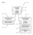
- FIG. 1 shows a system 10, constructed and operative according to the teachings of the present invention, for automatically acquiring a target with a narrow field-of-view gimbaled imaging sensor.
- system 10 has a target-detection subsystem 12 including at least one target-detection imaging sensor 14 having a first field-of-view.
- System 10 also includes a target-tracking subsystem 16 including an imaging sensor 18 having a second field-of-view significantly smaller than the first field-of-view, and a gimbal mechanism 20 for controlling a viewing direction of target-tracking sensor 18.
- a processing system 22, in communication with target-detection subsystem 12 and target-tracking subsystem 16, includes a target transfer module 24.
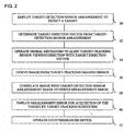
- the method begins when the system detects a target by use of target-detection subsystem 12 (step 30 ).
- Target transfer module 24 then processes data from target-detection subsystem 12 to determine a target direction vector (step 32 ) and operates gimbal mechanism 20 so as to align the viewing direction of target-tracking sensor 18 with the target direction vector (step 34 ).
- steps 30, 32 and 34 are supplemented with an image-processing based correction process.
- target transfer module 24 derives an image from target-tracking imaging sensor 18 and, at step 38, correlates the image with at least part of an image from the target-detection subsystem 12 to derive a misalignment error.
- Target transfer module 24 then transfers the misalignment error to target-tracking subsystem 16 where it is used to facilitate acquisition of the target (step 40 ), thereby ensuring reliable hand-off between target-detection subsystem 12 and target-tracking subsystem 16.
- the present invention provides a particularly elegant and effective enhancement to the reliability of an automated target acquisition system of the type described.
- the system makes use of the already present imaging sensors of the detection and tracking subsystems to provide image-processing-based self-correction of initial tracking misalignment, even where mechanical accuracy would otherwise be insufficient to ensure effective target acquisition.
- both target-detection subsystem 12 and target-tracking subsystem 16 are generally conventional systems of types commercially available for these and other functions. Suitable examples include, but are not limited to, the corresponding components of the PAWS-2 passive electrooptical missile warning system commercially available from Elisra Electronic Systems Ltd., Israel.
- the target-detection subsystem employs a plurality of staring FLIRs to cover the required near-panoramic FOV with an angular pixel resolution of between about 0.2° and about 0.5°.
- the target-detection subsystem also typically includes a number of additional components (not shown) as is generally known in the art.
- Functions of these components typically include: supporting operation of the sensor array, correcting for geometrical and sensitivity distortions inherent to the sensor arrangement, detecting targets; initial target filtering and false-target rejections; and providing data and/or image outputs relating to the target direction. All of these features are either well known or within the capabilities of one ordinarily skilled in the art, and will not be addressed here in detail.
- target-tracking subsystem 16 has a field-of-view significantly smaller, and resolution significantly higher, than that of each target-detection imaging sensor 14.
- sensor 18 typically has a total FOV which is less than 10% of the solid angle of the FOV for each sensor 14.
- the narrow FOV is less than 3%, and most preferably less than 2%, of the solid angle of the detection sensors 14, corresponding to an angular FOV ratio of at least 7:1.
- the angular resolutions of the two types of sensors differ greatly, with a factor of at least 2:1, preferably at least 5:1, and more preferably at least 10:1.
- the detection sensors 14 have a pixel resolution of 2-3 per degree while the tracking sensor 18 is typically in the range of 30-60 pixels per degree.
- Gimbal mechanism 20 is also typically a commercially available mechanism.
- a suitable countermeasure device 26 is generally associated with target-tracking subsystem 16.
- the details of the configuration for each particular type of countermeasure device 26 vary, as will be understood by one ordinarily skilled in the art.
- the countermeasure device 26 may advantageously be mounted on gimbal mechanism 20 so as to be mechanically linked (“boresighted") to move with sensor 18.
- Target transfer module 24 itself may be implemented as a software module run on a non-dedicated processing system, as a dedicated hardware module, or as a hardware-software combination known as "firmware".
- target-detections subsystem 12 target-tracking subsystem 16 and processing system 22 is somewhat arbitrary and may be varied considerably without departing from the scope of the present invention as defined in the appended claims. Specifically, it is possible that one or both of the subsystems 12 and 16 may be integrated with processing system 22 such that the processing system also forms an integral part of the corresponding subsystem(s).
- steps 30, 32 and 34 are generally similar to the operation of the Elisra PAWS-2 system mentioned above. These steps will not be described here in detail.
- the image from target-tracking sensor 18 acquired at step 36 is preferably a full frame image from the sensor, and is preprocessed to correct camera-induced distortions (geometrical and intensity) as is known in the art.
- the system samples a corresponding image from target-detection sensor 14 at a time as close as possible to the sampling time of the image from sensor 18.
- the image registration processing of step 38 is preferably performed on an image from sensor 14 sampled at a corresponding time half a second after the initial target detection.
- the image frame from sensor 14 is typically not a full sensor frame but rather is chosen to correspond to the expected FOV of sensor 18 with a surrounding margin to ensure good overlap.
- the width of the surrounding margin corresponds to between 50% and 100% of the corresponding dimension of the FOV of sensor 18, corresponding to a FOV of 4 to 9 times greater than the FOV of sensor 18 itself.
- the comparison image for step 38 may be a mosaic or compound image derived from more than one target-detection sensor 14.
- preprocessing is performed to correct for sensor-induced distortions.
- the images processed at step 38 have widely differing angular resolutions.
- Processing techniques for image registration between images of widely differing resolutions are well known in the art. It will be appreciated that the image registration is performed primarily by correlation of the background features of both images, since the target itself is typically small in both images. This allows registration of the images even in a case where severe misalignment puts the target outside the FOV of sensor 18.
- the misalignment error generated by step 38 may be expressed in any format which can be used by target-tracking subsystem 16 to facilitate target acquisition.
- the misalignment error may be expressed as a pixel position, or a pixel-displacement vector, indicative of the current target position within, or relative to, the current FOV of sensor 18. This pixel position is then used directly by target-tracking subsystem as an input to target acquisition processing algorithms in step 40. It will be noted that the pixel position may be a "virtual pixel position" lying outside the physical sensor array, indicating that a change of viewing direction is required to bring the target into the FOV.
- the misalignment error can be expressed in the form of an angular boresight correction which would bring the optical axis of sensor 18 into alignment with the target.
- the misalignment error may be used by target-tracking subsystem 16 to facilitate target acquisition without necessarily realigning the sensor to center the target in the field of view.
- gimbal mechanism 20 is operated normally as part of the tracking algorithms of subsystem 16 to maintain tracking of the target.
- the system preferably includes a countermeasure device 26, such as a DIRCM device as is known in the art.
- Countermeasure device 26 is preferably operated automatically at step 42 to destroy or disrupt operation of the incoming threat.
Applications Claiming Priority (2)
| Application Number | Priority Date | Filing Date | Title |
|---|---|---|---|
| IL16108204 | 2004-03-25 | ||
| IL161082A IL161082A (en) | 2004-03-25 | 2004-03-25 | System and method for automatically acquiring a target with a narrow field-of-view gimbaled imaging sensor |
Publications (2)
| Publication Number | Publication Date |
|---|---|
| EP1580518A1 true EP1580518A1 (de) | 2005-09-28 |
| EP1580518B1 EP1580518B1 (de) | 2014-04-23 |
Family
ID=34856854
Family Applications (1)
| Application Number | Title | Priority Date | Filing Date |
|---|---|---|---|
| EP05251848.7A Active EP1580518B1 (de) | 2004-03-25 | 2005-03-24 | System und Verfahren zur automatischen Zielerfassung mit einem Abbildungssensor und einer Kardanaufhängungsowie einem engen Gesichtsfeld |
Country Status (4)
| Country | Link |
|---|---|
| US (1) | US7636452B2 (de) |
| EP (1) | EP1580518B1 (de) |
| IL (1) | IL161082A (de) |
| ZA (1) | ZA200502454B (de) |
Cited By (6)
| Publication number | Priority date | Publication date | Assignee | Title |
|---|---|---|---|---|
| EP1811315A2 (de) | 2006-01-18 | 2007-07-25 | Rafael Armament Development Authority Ltd. | Profilerkennungssystem |
| EP2017650A1 (de) * | 2007-06-26 | 2009-01-21 | Honeywell International Inc. | Zielortungssystem |
| RU2481603C1 (ru) * | 2011-12-22 | 2013-05-10 | Михаил Витальевич Головань | Способ визирования |
| US9074847B1 (en) * | 2014-08-28 | 2015-07-07 | Flex Force Enterprises LLC | Stabilized weapon platform with active sense and adaptive motion control |
| WO2018201868A1 (zh) * | 2017-05-02 | 2018-11-08 | 深圳信息职业技术学院 | 一种基于多摄像头跟踪定位的反无人机装置及方法 |
| CN111787216A (zh) * | 2019-04-04 | 2020-10-16 | 南京非空航空科技有限公司 | 一种基于多摄像头的反无人机装置 |
Families Citing this family (18)
| Publication number | Priority date | Publication date | Assignee | Title |
|---|---|---|---|---|
| JP5041757B2 (ja) * | 2006-08-02 | 2012-10-03 | パナソニック株式会社 | カメラ制御装置およびカメラ制御システム |
| US8149392B1 (en) * | 2007-03-29 | 2012-04-03 | Bae Systems Information And Electronic Systems Integration Inc. | Method and apparatus for reducing handoff inaccuracies in a countermeasures system |
| JP4998156B2 (ja) * | 2007-08-30 | 2012-08-15 | ソニー株式会社 | 情報提示システム、情報提示装置、情報提示方法、プログラム並びにプログラムを記録した記録媒体 |
| KR101187909B1 (ko) * | 2007-10-04 | 2012-10-05 | 삼성테크윈 주식회사 | 감시 카메라 시스템 |
| US8217375B2 (en) | 2008-01-07 | 2012-07-10 | Bae Systems Information And Electronic Systems Integration Inc. | Integrated pod optical bench design |
| US9441922B2 (en) * | 2008-07-09 | 2016-09-13 | Bae Systems Information And Electronic Systems Integration Inc. | Method and apparatus for improving gimbal stability |
| TWI405457B (zh) * | 2008-12-18 | 2013-08-11 | Ind Tech Res Inst | 應用攝影機換手技術之多目標追蹤系統及其方法,與其智慧節點 |
| US8294560B2 (en) * | 2009-07-20 | 2012-10-23 | The United States Of America As Represented By The Secretary Of The Army | Method and apparatus for identifying threats using multiple sensors in a graphical user interface |
| US20120114229A1 (en) * | 2010-01-21 | 2012-05-10 | Guoqing Zhou | Orthorectification and mosaic of video flow |
| US10089327B2 (en) | 2011-08-18 | 2018-10-02 | Qualcomm Incorporated | Smart camera for sharing pictures automatically |
| US9223017B2 (en) * | 2012-05-30 | 2015-12-29 | Honeywell International Inc. | Systems and methods for enhanced awareness of obstacle proximity during taxi operations |
| US9373051B2 (en) * | 2012-06-14 | 2016-06-21 | Insitu, Inc. | Statistical approach to identifying and tracking targets within captured image data |
| US9380275B2 (en) | 2013-01-30 | 2016-06-28 | Insitu, Inc. | Augmented video system providing enhanced situational awareness |
| US20160025850A1 (en) * | 2014-06-03 | 2016-01-28 | Watchstander, LLC | Autonomous Robotic Mobile Threat Security System |
| US9936133B2 (en) | 2015-08-19 | 2018-04-03 | Harris Corporation | Gimbaled camera object tracking system |
| US10101125B2 (en) | 2016-06-15 | 2018-10-16 | The United States Of America, As Represented By The Secretary Of The Navy | Precision engagement system |
| US10510158B1 (en) | 2017-11-13 | 2019-12-17 | Amazon Technologies, Inc. | Collaborative airborne object tracking systems and methods |
| EP3891529A1 (de) * | 2018-12-05 | 2021-10-13 | Telefonaktiebolaget Lm Ericsson (Publ) | Anvisierung von objekten |
Citations (9)
| Publication number | Priority date | Publication date | Assignee | Title |
|---|---|---|---|---|
| US2968997A (en) * | 1947-05-09 | 1961-01-24 | Sperry Rand Corp | Cross connected servo mechanism for a turret gun directing system |
| EP0111192A1 (de) * | 1982-12-06 | 1984-06-20 | Hollandse Signaalapparaten B.V. | Integriertes Waffensteuersystem |
| US4622554A (en) * | 1983-01-18 | 1986-11-11 | 501 Hollandse Signaalapparaten B.V. | Pulse radar apparatus |
| WO1988008952A1 (en) * | 1987-05-15 | 1988-11-17 | Contraves Ag | Alignment process for gun fire control device and gun fire control device for implementation of the process |
| US5773745A (en) * | 1994-06-06 | 1998-06-30 | Alliant Defense Electronic Systems, Inc. | Method and device for cutting and dispensing of adversarial interaction countermeasures |
| US6324955B1 (en) * | 1992-04-20 | 2001-12-04 | Raytheon Company | Explosive countermeasure device |
| US6429446B1 (en) * | 1975-04-28 | 2002-08-06 | Bae Systems Information And Electronic Systems Integration, Inc. | Multiple infrared missile jammer |
| US6480140B1 (en) * | 2000-06-09 | 2002-11-12 | Jonathan B. Rosefsky | Apparatus and method for providing a deception response system |
| US6587486B1 (en) * | 1997-10-16 | 2003-07-01 | Eads Deutschland Gmbh | Laser beam source for a directional infrared countermeasures (DIRCM) weapon system |
Family Cites Families (66)
| Publication number | Priority date | Publication date | Assignee | Title |
|---|---|---|---|---|
| US2172472A (en) * | 1936-01-18 | 1939-09-12 | Grow Bros | Fish-scaling machine |
| US2664591A (en) * | 1951-08-30 | 1954-01-05 | Ruth C Brophy | Fish scaling machine |
| US2930894A (en) * | 1954-07-13 | 1960-03-29 | Republic Aviat Corp | Optical sighting and tracking device |
| US2795812A (en) * | 1955-11-21 | 1957-06-18 | Samuel M Godfrey | Fish scaling machine |
| US3088164A (en) * | 1961-06-27 | 1963-05-07 | Frederick L Moore | Fish scaling machine |
| US3787927A (en) * | 1972-05-26 | 1974-01-29 | A Simard | Fish scaling machine |
| US3986682A (en) * | 1974-09-17 | 1976-10-19 | The United States Of America As Represented By The Secretary Of The Navy | Ibis guidance and control system |
| FR2389865B1 (de) * | 1977-05-06 | 1981-11-20 | Realisa Electroniques Et | |
| GB1563662A (en) * | 1977-06-02 | 1980-03-26 | St Clair Fisheries Ltd | Treatment of fish |
| US4485526A (en) * | 1982-08-09 | 1984-12-04 | Opanasenko Walter W | Fish scaling apparatus |
| US4598884A (en) * | 1984-11-28 | 1986-07-08 | General Dynamics Pomona Division | Infrared target sensor and system |
| DK164385A (da) * | 1985-04-12 | 1986-10-13 | Slagteriernes Forskningsinst | Apparat til skoldning af slagtekroppe |
| US5123327A (en) * | 1985-10-15 | 1992-06-23 | The Boeing Company | Automatic turret tracking apparatus for a light air defense system |
| FR2635379B1 (fr) * | 1988-08-12 | 1993-11-12 | Sagem | Installation de conduite de tir a compensation des erreurs de pointage |
| US4868950A (en) * | 1989-01-03 | 1989-09-26 | Centennial Machine Company, Inc. | Fowl scalding apparatus and method |
| GB2233183A (en) * | 1989-06-09 | 1991-01-02 | Marconi Gec Ltd | Imaging system |
| US5164827A (en) * | 1991-08-22 | 1992-11-17 | Sensormatic Electronics Corporation | Surveillance system with master camera control of slave cameras |
| IL102973A0 (en) * | 1991-09-04 | 1993-02-21 | Westinghouse Electric Corp | Optically multiplexed dual line of sight flir system |
| US5229540A (en) * | 1992-05-26 | 1993-07-20 | The United States Of America As Represented By The Secretary Of The Army | Tank alerting system |
| US5230652A (en) * | 1992-08-07 | 1993-07-27 | Mohammed Alam | Fish cleaning device |
| US5345304A (en) * | 1992-12-17 | 1994-09-06 | Texas Instruments Incorporated | Integrated LADAR/FLIR sensor |
| CA2148231C (en) * | 1993-01-29 | 1999-01-12 | Michael Haysom Bianchi | Automatic tracking camera control system |
| US5379676A (en) * | 1993-04-05 | 1995-01-10 | Contraves Usa | Fire control system |
| US5596509A (en) * | 1994-05-12 | 1997-01-21 | The Regents Of The University Of California | Passive infrared bullet detection and tracking |
| US5789762A (en) * | 1994-09-14 | 1998-08-04 | Semiconductor Energy Laboratory Co., Ltd. | Semiconductor active matrix circuit |
| US6019033A (en) * | 1994-11-07 | 2000-02-01 | Frigoscandia, Inc. | Apparatus for steam pasteurization of food |
| US5520576A (en) * | 1994-11-09 | 1996-05-28 | Pisces Industries, Ltd. | Fish filleting machine |
| CA2155719C (en) * | 1994-11-22 | 2005-11-01 | Terry Laurence Glatt | Video surveillance system with pilot and slave cameras |
| DE19601961C2 (de) * | 1996-01-20 | 1998-11-05 | Dornier Gmbh | Einrichtung zur Erleichterung des Auffindens von Zielen an einem Waffensystem |
| US5936229A (en) * | 1996-04-02 | 1999-08-10 | Trw Inc. | Tracking means for distant ballistic missile targets comprising means for tracking largest radius of curvature |
| US5879732A (en) * | 1996-09-10 | 1999-03-09 | Boc Group, Inc. | Food processing method |
| JP2998791B2 (ja) * | 1996-10-31 | 2000-01-11 | 日本電気株式会社 | 三次元構造推定装置 |
| US5918305A (en) * | 1997-08-27 | 1999-06-29 | Trw Inc. | Imaging self-referencing tracker and associated methodology |
| US6215519B1 (en) * | 1998-03-04 | 2001-04-10 | The Trustees Of Columbia University In The City Of New York | Combined wide angle and narrow angle imaging system and method for surveillance and monitoring |
| US6369885B1 (en) * | 1998-05-05 | 2002-04-09 | Lockheed Martin Corporation | Closed-loop infrared countermeasure system using high frame rate infrared receiver |
| US6274887B1 (en) * | 1998-11-02 | 2001-08-14 | Semiconductor Energy Laboratory Co., Ltd. | Semiconductor device and manufacturing method therefor |
| US6617644B1 (en) * | 1998-11-09 | 2003-09-09 | Semiconductor Energy Laboratory Co., Ltd. | Semiconductor device and method of manufacturing the same |
| US6501098B2 (en) * | 1998-11-25 | 2002-12-31 | Semiconductor Energy Laboratory Co, Ltd. | Semiconductor device |
| US6365917B1 (en) * | 1998-11-25 | 2002-04-02 | Semiconductor Energy Laboratory Co., Ltd. | Semiconductor device |
| US6469317B1 (en) * | 1998-12-18 | 2002-10-22 | Semiconductor Energy Laboratory Co., Ltd. | Semiconductor device and method of fabricating the same |
| US6380558B1 (en) * | 1998-12-29 | 2002-04-30 | Semiconductor Energy Laboratory Co., Ltd. | Semiconductor device and method of fabricating the same |
| US6393136B1 (en) * | 1999-01-04 | 2002-05-21 | International Business Machines Corporation | Method and apparatus for determining eye contact |
| US7177447B2 (en) * | 1999-02-23 | 2007-02-13 | Lockheed Martin Corporation | Real-time multi-stage infrared image-based tracking system |
| US6690374B2 (en) * | 1999-05-12 | 2004-02-10 | Imove, Inc. | Security camera system for tracking moving objects in both forward and reverse directions |
| GB9918248D0 (en) * | 1999-08-04 | 1999-10-06 | Matra Bae Dynamics Uk Ltd | Improvements in and relating to surveillance systems |
| US6368203B1 (en) * | 2000-01-13 | 2002-04-09 | Jersey Global International Sa | Method for scaling fresh fish and removing its internal organs and device for implementation of the offered method |
| US20020005902A1 (en) * | 2000-06-02 | 2002-01-17 | Yuen Henry C. | Automatic video recording system using wide-and narrow-field cameras |
| US7006950B1 (en) * | 2000-06-12 | 2006-02-28 | Siemens Corporate Research, Inc. | Statistical modeling and performance characterization of a real-time dual camera surveillance system |
| US7027083B2 (en) * | 2001-02-12 | 2006-04-11 | Carnegie Mellon University | System and method for servoing on a moving fixation point within a dynamic scene |
| US7130490B2 (en) * | 2001-05-14 | 2006-10-31 | Elder James H | Attentive panoramic visual sensor |
| IL145730A0 (en) * | 2001-10-01 | 2003-06-24 | Rafael Armament Dev Authority | Improved directional infrared counter measure |
| CA2359269A1 (en) * | 2001-10-17 | 2003-04-17 | Biodentity Systems Corporation | Face imaging system for recordal and automated identity confirmation |
| AU2003207799A1 (en) * | 2002-02-04 | 2003-09-02 | Bae Systems Information And Electronic Systems Integration Inc. | Reentry vehicle interceptor with ir and variable fov laser radar |
| JP4100934B2 (ja) * | 2002-02-28 | 2008-06-11 | シャープ株式会社 | 複合カメラシステム、ズームカメラ制御方法およびズームカメラ制御プログラム |
| US6864965B2 (en) * | 2002-03-12 | 2005-03-08 | Bae Systems Information And Electronic Systems Integration Inc. | Dual-mode focal plane array for missile seekers |
| JP2003284053A (ja) * | 2002-03-27 | 2003-10-03 | Minolta Co Ltd | 監視カメラシステムおよび監視カメラ制御装置 |
| US7129981B2 (en) * | 2002-06-27 | 2006-10-31 | International Business Machines Corporation | Rendering system and method for images having differing foveal area and peripheral view area resolutions |
| JP2006503299A (ja) * | 2002-10-18 | 2006-01-26 | ビーエイイー・システムズ・インフォメーション・アンド・エレクトロニック・システムズ・インテグレイション・インコーポレーテッド | 可変視野を提供するために有向妨害(directedcountermeasure)システム内で光学的歪みを使用する方法及び装置 |
| US6836320B2 (en) * | 2002-10-23 | 2004-12-28 | Ae Systems Information And Electronic Systems Integration Inc. | Method and apparatus for active boresight correction |
| US20050134685A1 (en) * | 2003-12-22 | 2005-06-23 | Objectvideo, Inc. | Master-slave automated video-based surveillance system |
| US6873893B1 (en) * | 2003-08-01 | 2005-03-29 | The United States Of America As Represented By The Secretary Of The Navy | Missile warning and protection system for aircraft platforms |
| US7551121B1 (en) * | 2004-03-12 | 2009-06-23 | Oceanit Laboratories, Inc. | Multi-target-tracking optical sensor-array technology |
| US7542588B2 (en) * | 2004-04-30 | 2009-06-02 | International Business Machines Corporation | System and method for assuring high resolution imaging of distinctive characteristics of a moving object |
| JP2008507229A (ja) * | 2004-07-19 | 2008-03-06 | グランドアイ,エルティーディー | 広角ビデオカメラのズーム機能の自動拡張 |
| US7463753B2 (en) * | 2004-09-15 | 2008-12-09 | Raytheon Company | FLIR-to-missile boresight correlation and non-uniformity compensation of the missile seeker |
| US20060203090A1 (en) * | 2004-12-04 | 2006-09-14 | Proximex, Corporation | Video surveillance using stationary-dynamic camera assemblies for wide-area video surveillance and allow for selective focus-of-attention |
-
2004
- 2004-03-25 IL IL161082A patent/IL161082A/en active IP Right Grant
-
2005
- 2005-03-23 US US11/086,466 patent/US7636452B2/en active Active
- 2005-03-24 EP EP05251848.7A patent/EP1580518B1/de active Active
- 2005-03-24 ZA ZA200502454A patent/ZA200502454B/xx unknown
Patent Citations (9)
| Publication number | Priority date | Publication date | Assignee | Title |
|---|---|---|---|---|
| US2968997A (en) * | 1947-05-09 | 1961-01-24 | Sperry Rand Corp | Cross connected servo mechanism for a turret gun directing system |
| US6429446B1 (en) * | 1975-04-28 | 2002-08-06 | Bae Systems Information And Electronic Systems Integration, Inc. | Multiple infrared missile jammer |
| EP0111192A1 (de) * | 1982-12-06 | 1984-06-20 | Hollandse Signaalapparaten B.V. | Integriertes Waffensteuersystem |
| US4622554A (en) * | 1983-01-18 | 1986-11-11 | 501 Hollandse Signaalapparaten B.V. | Pulse radar apparatus |
| WO1988008952A1 (en) * | 1987-05-15 | 1988-11-17 | Contraves Ag | Alignment process for gun fire control device and gun fire control device for implementation of the process |
| US6324955B1 (en) * | 1992-04-20 | 2001-12-04 | Raytheon Company | Explosive countermeasure device |
| US5773745A (en) * | 1994-06-06 | 1998-06-30 | Alliant Defense Electronic Systems, Inc. | Method and device for cutting and dispensing of adversarial interaction countermeasures |
| US6587486B1 (en) * | 1997-10-16 | 2003-07-01 | Eads Deutschland Gmbh | Laser beam source for a directional infrared countermeasures (DIRCM) weapon system |
| US6480140B1 (en) * | 2000-06-09 | 2002-11-12 | Jonathan B. Rosefsky | Apparatus and method for providing a deception response system |
Cited By (9)
| Publication number | Priority date | Publication date | Assignee | Title |
|---|---|---|---|---|
| EP1811315A2 (de) | 2006-01-18 | 2007-07-25 | Rafael Armament Development Authority Ltd. | Profilerkennungssystem |
| EP1811315A3 (de) * | 2006-01-18 | 2008-07-30 | Rafael Armament Development Authority Ltd. | Profilerkennungssystem |
| US7492308B2 (en) | 2006-01-18 | 2009-02-17 | Rafael Advanced Defense Systems Ltd. | Threat detection system |
| EP2017650A1 (de) * | 2007-06-26 | 2009-01-21 | Honeywell International Inc. | Zielortungssystem |
| RU2481603C1 (ru) * | 2011-12-22 | 2013-05-10 | Михаил Витальевич Головань | Способ визирования |
| US9074847B1 (en) * | 2014-08-28 | 2015-07-07 | Flex Force Enterprises LLC | Stabilized weapon platform with active sense and adaptive motion control |
| WO2018201868A1 (zh) * | 2017-05-02 | 2018-11-08 | 深圳信息职业技术学院 | 一种基于多摄像头跟踪定位的反无人机装置及方法 |
| US11629937B2 (en) | 2017-05-02 | 2023-04-18 | Shenzhen Institute Of Information Technology | Device and method of anti-unmanned aerial vehicle based on multi-camera tracking and positioning |
| CN111787216A (zh) * | 2019-04-04 | 2020-10-16 | 南京非空航空科技有限公司 | 一种基于多摄像头的反无人机装置 |
Also Published As
| Publication number | Publication date |
|---|---|
| US20050218259A1 (en) | 2005-10-06 |
| ZA200502454B (en) | 2005-10-10 |
| EP1580518B1 (de) | 2014-04-23 |
| US7636452B2 (en) | 2009-12-22 |
| IL161082A (en) | 2008-08-07 |
Similar Documents
| Publication | Publication Date | Title |
|---|---|---|
| US7636452B2 (en) | System and method for automatically acquiring a target with a narrow field-of-view gimbaled imaging sensor | |
| US7733465B2 (en) | System and method for transitioning from a missile warning system to a fine tracking system in a directional infrared countermeasures system | |
| US9207053B2 (en) | Harmonic shuttered seeker | |
| US7899644B2 (en) | Threat launch detection system and method | |
| EP2816310B1 (de) | Laserunterstützter, passiver Sucher | |
| US9494687B2 (en) | Seeker having scanning-snapshot FPA | |
| US5918305A (en) | Imaging self-referencing tracker and associated methodology | |
| US20090283598A1 (en) | Image Detection System and Methods | |
| US4424943A (en) | Tracking system | |
| US11435164B2 (en) | Boresighting device and method | |
| NO323310B1 (no) | Fremgangsmate og anordning for a beskytte luftfartoy mot missiltrusler | |
| CA2243752C (en) | Magic mirror hot spot tracker | |
| US6750806B2 (en) | Method of tracking a target and target tracking system | |
| US8526671B2 (en) | Threat detection sensor | |
| AU2014282795B2 (en) | Threat warning system integrating flash event and transmitted laser detection | |
| US10209343B1 (en) | Weapon fire detection and localization system for electro-optical sensors | |
| RU2697939C1 (ru) | Способ автоматизации целеуказания при прицеливании на вертолетном комплексе | |
| US6260792B1 (en) | Tracking and guidance system with modulated missile-mounted laser beacon | |
| RU2726301C1 (ru) | Вертолетный комплекс современного бортового вооружения | |
| EP4284717A1 (de) | System und verfahren zur netzaufnahme eines unbemannten luftfahrzeugs | |
| JPH06137791A (ja) | 画像射撃統制方法及び装置 |
Legal Events
| Date | Code | Title | Description |
|---|---|---|---|
| PUAI | Public reference made under article 153(3) epc to a published international application that has entered the european phase |
Free format text: ORIGINAL CODE: 0009012 |
|
| AK | Designated contracting states |
Kind code of ref document: A1 Designated state(s): AT BE BG CH CY CZ DE DK EE ES FI FR GB GR HU IE IS IT LI LT LU MC NL PL PT RO SE SI SK TR |
|
| AX | Request for extension of the european patent |
Extension state: AL BA HR LV MK YU |
|
| 17P | Request for examination filed |
Effective date: 20060222 |
|
| AKX | Designation fees paid |
Designated state(s): AT BE BG CH CY CZ DE DK EE ES FI FR GB GR HU IE IS IT LI LT LU MC NL PL PT RO SE SI SK TR |
|
| 17Q | First examination report despatched |
Effective date: 20130703 |
|
| GRAP | Despatch of communication of intention to grant a patent |
Free format text: ORIGINAL CODE: EPIDOSNIGR1 |
|
| INTG | Intention to grant announced |
Effective date: 20140102 |
|
| GRAS | Grant fee paid |
Free format text: ORIGINAL CODE: EPIDOSNIGR3 |
|
| GRAA | (expected) grant |
Free format text: ORIGINAL CODE: 0009210 |
|
| AK | Designated contracting states |
Kind code of ref document: B1 Designated state(s): AT BE BG CH CY CZ DE DK EE ES FI FR GB GR HU IE IS IT LI LT LU MC NL PL PT RO SE SI SK TR |
|
| REG | Reference to a national code |
Ref country code: GB Ref legal event code: FG4D |
|
| REG | Reference to a national code |
Ref country code: CH Ref legal event code: EP |
|
| REG | Reference to a national code |
Ref country code: AT Ref legal event code: REF Ref document number: 664099 Country of ref document: AT Kind code of ref document: T Effective date: 20140515 |
|
| REG | Reference to a national code |
Ref country code: IE Ref legal event code: FG4D |
|
| REG | Reference to a national code |
Ref country code: DE Ref legal event code: R096 Ref document number: 602005043356 Country of ref document: DE Effective date: 20140528 |
|
| REG | Reference to a national code |
Ref country code: AT Ref legal event code: MK05 Ref document number: 664099 Country of ref document: AT Kind code of ref document: T Effective date: 20140423 |
|
| REG | Reference to a national code |
Ref country code: NL Ref legal event code: VDEP Effective date: 20140423 |
|
| REG | Reference to a national code |
Ref country code: LT Ref legal event code: MG4D |
|
| PG25 | Lapsed in a contracting state [announced via postgrant information from national office to epo] |
Ref country code: NL Free format text: LAPSE BECAUSE OF FAILURE TO SUBMIT A TRANSLATION OF THE DESCRIPTION OR TO PAY THE FEE WITHIN THE PRESCRIBED TIME-LIMIT Effective date: 20140423 Ref country code: IS Free format text: LAPSE BECAUSE OF FAILURE TO SUBMIT A TRANSLATION OF THE DESCRIPTION OR TO PAY THE FEE WITHIN THE PRESCRIBED TIME-LIMIT Effective date: 20140823 Ref country code: FI Free format text: LAPSE BECAUSE OF FAILURE TO SUBMIT A TRANSLATION OF THE DESCRIPTION OR TO PAY THE FEE WITHIN THE PRESCRIBED TIME-LIMIT Effective date: 20140423 Ref country code: GR Free format text: LAPSE BECAUSE OF FAILURE TO SUBMIT A TRANSLATION OF THE DESCRIPTION OR TO PAY THE FEE WITHIN THE PRESCRIBED TIME-LIMIT Effective date: 20140724 Ref country code: CY Free format text: LAPSE BECAUSE OF FAILURE TO SUBMIT A TRANSLATION OF THE DESCRIPTION OR TO PAY THE FEE WITHIN THE PRESCRIBED TIME-LIMIT Effective date: 20140423 Ref country code: LT Free format text: LAPSE BECAUSE OF FAILURE TO SUBMIT A TRANSLATION OF THE DESCRIPTION OR TO PAY THE FEE WITHIN THE PRESCRIBED TIME-LIMIT Effective date: 20140423 Ref country code: BG Free format text: LAPSE BECAUSE OF FAILURE TO SUBMIT A TRANSLATION OF THE DESCRIPTION OR TO PAY THE FEE WITHIN THE PRESCRIBED TIME-LIMIT Effective date: 20140723 |
|
| PG25 | Lapsed in a contracting state [announced via postgrant information from national office to epo] |
Ref country code: AT Free format text: LAPSE BECAUSE OF FAILURE TO SUBMIT A TRANSLATION OF THE DESCRIPTION OR TO PAY THE FEE WITHIN THE PRESCRIBED TIME-LIMIT Effective date: 20140423 Ref country code: PL Free format text: LAPSE BECAUSE OF FAILURE TO SUBMIT A TRANSLATION OF THE DESCRIPTION OR TO PAY THE FEE WITHIN THE PRESCRIBED TIME-LIMIT Effective date: 20140423 Ref country code: SE Free format text: LAPSE BECAUSE OF FAILURE TO SUBMIT A TRANSLATION OF THE DESCRIPTION OR TO PAY THE FEE WITHIN THE PRESCRIBED TIME-LIMIT Effective date: 20140423 Ref country code: ES Free format text: LAPSE BECAUSE OF FAILURE TO SUBMIT A TRANSLATION OF THE DESCRIPTION OR TO PAY THE FEE WITHIN THE PRESCRIBED TIME-LIMIT Effective date: 20140423 |
|
| PG25 | Lapsed in a contracting state [announced via postgrant information from national office to epo] |
Ref country code: PT Free format text: LAPSE BECAUSE OF FAILURE TO SUBMIT A TRANSLATION OF THE DESCRIPTION OR TO PAY THE FEE WITHIN THE PRESCRIBED TIME-LIMIT Effective date: 20140825 |
|
| REG | Reference to a national code |
Ref country code: DE Ref legal event code: R097 Ref document number: 602005043356 Country of ref document: DE |
|
| PG25 | Lapsed in a contracting state [announced via postgrant information from national office to epo] |
Ref country code: BE Free format text: LAPSE BECAUSE OF FAILURE TO SUBMIT A TRANSLATION OF THE DESCRIPTION OR TO PAY THE FEE WITHIN THE PRESCRIBED TIME-LIMIT Effective date: 20140423 Ref country code: EE Free format text: LAPSE BECAUSE OF FAILURE TO SUBMIT A TRANSLATION OF THE DESCRIPTION OR TO PAY THE FEE WITHIN THE PRESCRIBED TIME-LIMIT Effective date: 20140423 Ref country code: SK Free format text: LAPSE BECAUSE OF FAILURE TO SUBMIT A TRANSLATION OF THE DESCRIPTION OR TO PAY THE FEE WITHIN THE PRESCRIBED TIME-LIMIT Effective date: 20140423 Ref country code: CZ Free format text: LAPSE BECAUSE OF FAILURE TO SUBMIT A TRANSLATION OF THE DESCRIPTION OR TO PAY THE FEE WITHIN THE PRESCRIBED TIME-LIMIT Effective date: 20140423 Ref country code: RO Free format text: LAPSE BECAUSE OF FAILURE TO SUBMIT A TRANSLATION OF THE DESCRIPTION OR TO PAY THE FEE WITHIN THE PRESCRIBED TIME-LIMIT Effective date: 20140423 Ref country code: DK Free format text: LAPSE BECAUSE OF FAILURE TO SUBMIT A TRANSLATION OF THE DESCRIPTION OR TO PAY THE FEE WITHIN THE PRESCRIBED TIME-LIMIT Effective date: 20140423 |
|
| PLBE | No opposition filed within time limit |
Free format text: ORIGINAL CODE: 0009261 |
|
| STAA | Information on the status of an ep patent application or granted ep patent |
Free format text: STATUS: NO OPPOSITION FILED WITHIN TIME LIMIT |
|
| PG25 | Lapsed in a contracting state [announced via postgrant information from national office to epo] |
Ref country code: IT Free format text: LAPSE BECAUSE OF FAILURE TO SUBMIT A TRANSLATION OF THE DESCRIPTION OR TO PAY THE FEE WITHIN THE PRESCRIBED TIME-LIMIT Effective date: 20140423 |
|
| 26N | No opposition filed |
Effective date: 20150126 |
|
| REG | Reference to a national code |
Ref country code: DE Ref legal event code: R097 Ref document number: 602005043356 Country of ref document: DE Effective date: 20150126 |
|
| PG25 | Lapsed in a contracting state [announced via postgrant information from national office to epo] |
Ref country code: SI Free format text: LAPSE BECAUSE OF FAILURE TO SUBMIT A TRANSLATION OF THE DESCRIPTION OR TO PAY THE FEE WITHIN THE PRESCRIBED TIME-LIMIT Effective date: 20140423 |
|
| PG25 | Lapsed in a contracting state [announced via postgrant information from national office to epo] |
Ref country code: MC Free format text: LAPSE BECAUSE OF FAILURE TO SUBMIT A TRANSLATION OF THE DESCRIPTION OR TO PAY THE FEE WITHIN THE PRESCRIBED TIME-LIMIT Effective date: 20140423 Ref country code: LU Free format text: LAPSE BECAUSE OF FAILURE TO SUBMIT A TRANSLATION OF THE DESCRIPTION OR TO PAY THE FEE WITHIN THE PRESCRIBED TIME-LIMIT Effective date: 20150324 |
|
| REG | Reference to a national code |
Ref country code: CH Ref legal event code: PL |
|
| REG | Reference to a national code |
Ref country code: IE Ref legal event code: MM4A |
|
| PG25 | Lapsed in a contracting state [announced via postgrant information from national office to epo] |
Ref country code: CH Free format text: LAPSE BECAUSE OF NON-PAYMENT OF DUE FEES Effective date: 20150331 Ref country code: IE Free format text: LAPSE BECAUSE OF NON-PAYMENT OF DUE FEES Effective date: 20150324 Ref country code: LI Free format text: LAPSE BECAUSE OF NON-PAYMENT OF DUE FEES Effective date: 20150331 |
|
| REG | Reference to a national code |
Ref country code: FR Ref legal event code: PLFP Year of fee payment: 12 |
|
| REG | Reference to a national code |
Ref country code: FR Ref legal event code: PLFP Year of fee payment: 13 |
|
| PG25 | Lapsed in a contracting state [announced via postgrant information from national office to epo] |
Ref country code: HU Free format text: LAPSE BECAUSE OF FAILURE TO SUBMIT A TRANSLATION OF THE DESCRIPTION OR TO PAY THE FEE WITHIN THE PRESCRIBED TIME-LIMIT; INVALID AB INITIO Effective date: 20050324 |
|
| PG25 | Lapsed in a contracting state [announced via postgrant information from national office to epo] |
Ref country code: TR Free format text: LAPSE BECAUSE OF FAILURE TO SUBMIT A TRANSLATION OF THE DESCRIPTION OR TO PAY THE FEE WITHIN THE PRESCRIBED TIME-LIMIT Effective date: 20140423 |
|
| REG | Reference to a national code |
Ref country code: FR Ref legal event code: PLFP Year of fee payment: 14 |
|
| PGFP | Annual fee paid to national office [announced via postgrant information from national office to epo] |
Ref country code: FR Payment date: 20230208 Year of fee payment: 19 |
|
| PGFP | Annual fee paid to national office [announced via postgrant information from national office to epo] |
Ref country code: GB Payment date: 20230202 Year of fee payment: 19 Ref country code: DE Payment date: 20230125 Year of fee payment: 19 |