EP1580030B1 - Pneumatic tire - Google Patents
Pneumatic tire Download PDFInfo
- Publication number
- EP1580030B1 EP1580030B1 EP05001052A EP05001052A EP1580030B1 EP 1580030 B1 EP1580030 B1 EP 1580030B1 EP 05001052 A EP05001052 A EP 05001052A EP 05001052 A EP05001052 A EP 05001052A EP 1580030 B1 EP1580030 B1 EP 1580030B1
- Authority
- EP
- European Patent Office
- Prior art keywords
- band
- tire
- cord
- belt
- side portion
- Prior art date
- Legal status (The legal status is an assumption and is not a legal conclusion. Google has not performed a legal analysis and makes no representation as to the accuracy of the status listed.)
- Ceased
Links
- 229920001778 nylon Polymers 0.000 claims description 26
- 239000002131 composite material Substances 0.000 claims description 14
- 239000011324 bead Substances 0.000 claims description 11
- 229920006231 aramid fiber Polymers 0.000 claims description 9
- 239000004677 Nylon Substances 0.000 description 17
- 239000000835 fiber Substances 0.000 description 17
- 238000005096 rolling process Methods 0.000 description 17
- 239000011112 polyethylene naphthalate Substances 0.000 description 13
- 229920003207 poly(ethylene-2,6-naphthalate) Polymers 0.000 description 12
- 241000254043 Melolonthinae Species 0.000 description 6
- 230000000052 comparative effect Effects 0.000 description 6
- 239000000463 material Substances 0.000 description 6
- 238000011156 evaluation Methods 0.000 description 5
- 229920000728 polyester Polymers 0.000 description 3
- 229910000831 Steel Inorganic materials 0.000 description 2
- 229920002978 Vinylon Polymers 0.000 description 2
- 239000004744 fabric Substances 0.000 description 2
- 238000005259 measurement Methods 0.000 description 2
- -1 polyethylene naphthalate Polymers 0.000 description 2
- 239000010959 steel Substances 0.000 description 2
- 229920000297 Rayon Polymers 0.000 description 1
- 239000010426 asphalt Substances 0.000 description 1
- 238000006073 displacement reaction Methods 0.000 description 1
- 230000002093 peripheral effect Effects 0.000 description 1
- 239000002964 rayon Substances 0.000 description 1
- 230000001953 sensory effect Effects 0.000 description 1
- 230000035939 shock Effects 0.000 description 1
- 238000002834 transmittance Methods 0.000 description 1
Images


Classifications
-
- B—PERFORMING OPERATIONS; TRANSPORTING
- B60—VEHICLES IN GENERAL
- B60C—VEHICLE TYRES; TYRE INFLATION; TYRE CHANGING; CONNECTING VALVES TO INFLATABLE ELASTIC BODIES IN GENERAL; DEVICES OR ARRANGEMENTS RELATED TO TYRES
- B60C9/00—Reinforcements or ply arrangement of pneumatic tyres
- B60C9/18—Structure or arrangement of belts or breakers, crown-reinforcing or cushioning layers
- B60C9/20—Structure or arrangement of belts or breakers, crown-reinforcing or cushioning layers built-up from rubberised plies each having all cords arranged substantially parallel
- B60C9/22—Structure or arrangement of belts or breakers, crown-reinforcing or cushioning layers built-up from rubberised plies each having all cords arranged substantially parallel the plies being arranged with all cords disposed along the circumference of the tyre
-
- B—PERFORMING OPERATIONS; TRANSPORTING
- B60—VEHICLES IN GENERAL
- B60C—VEHICLE TYRES; TYRE INFLATION; TYRE CHANGING; CONNECTING VALVES TO INFLATABLE ELASTIC BODIES IN GENERAL; DEVICES OR ARRANGEMENTS RELATED TO TYRES
- B60C9/00—Reinforcements or ply arrangement of pneumatic tyres
- B60C9/18—Structure or arrangement of belts or breakers, crown-reinforcing or cushioning layers
- B60C9/28—Structure or arrangement of belts or breakers, crown-reinforcing or cushioning layers characterised by the belt or breaker dimensions or curvature relative to carcass
-
- B—PERFORMING OPERATIONS; TRANSPORTING
- B60—VEHICLES IN GENERAL
- B60C—VEHICLE TYRES; TYRE INFLATION; TYRE CHANGING; CONNECTING VALVES TO INFLATABLE ELASTIC BODIES IN GENERAL; DEVICES OR ARRANGEMENTS RELATED TO TYRES
- B60C9/00—Reinforcements or ply arrangement of pneumatic tyres
- B60C9/18—Structure or arrangement of belts or breakers, crown-reinforcing or cushioning layers
- B60C9/20—Structure or arrangement of belts or breakers, crown-reinforcing or cushioning layers built-up from rubberised plies each having all cords arranged substantially parallel
- B60C9/22—Structure or arrangement of belts or breakers, crown-reinforcing or cushioning layers built-up from rubberised plies each having all cords arranged substantially parallel the plies being arranged with all cords disposed along the circumference of the tyre
- B60C2009/2223—Structure or arrangement of belts or breakers, crown-reinforcing or cushioning layers built-up from rubberised plies each having all cords arranged substantially parallel the plies being arranged with all cords disposed along the circumference of the tyre with an interrupted zero degree ply, e.g. using two or more portions for the same ply
-
- B—PERFORMING OPERATIONS; TRANSPORTING
- B60—VEHICLES IN GENERAL
- B60C—VEHICLE TYRES; TYRE INFLATION; TYRE CHANGING; CONNECTING VALVES TO INFLATABLE ELASTIC BODIES IN GENERAL; DEVICES OR ARRANGEMENTS RELATED TO TYRES
- B60C9/00—Reinforcements or ply arrangement of pneumatic tyres
- B60C9/18—Structure or arrangement of belts or breakers, crown-reinforcing or cushioning layers
- B60C9/20—Structure or arrangement of belts or breakers, crown-reinforcing or cushioning layers built-up from rubberised plies each having all cords arranged substantially parallel
- B60C9/22—Structure or arrangement of belts or breakers, crown-reinforcing or cushioning layers built-up from rubberised plies each having all cords arranged substantially parallel the plies being arranged with all cords disposed along the circumference of the tyre
- B60C2009/2252—Physical properties or dimension of the zero degree ply cords
- B60C2009/2261—Modulus of the cords
-
- B—PERFORMING OPERATIONS; TRANSPORTING
- B60—VEHICLES IN GENERAL
- B60C—VEHICLE TYRES; TYRE INFLATION; TYRE CHANGING; CONNECTING VALVES TO INFLATABLE ELASTIC BODIES IN GENERAL; DEVICES OR ARRANGEMENTS RELATED TO TYRES
- B60C9/00—Reinforcements or ply arrangement of pneumatic tyres
- B60C9/18—Structure or arrangement of belts or breakers, crown-reinforcing or cushioning layers
- B60C9/20—Structure or arrangement of belts or breakers, crown-reinforcing or cushioning layers built-up from rubberised plies each having all cords arranged substantially parallel
- B60C9/22—Structure or arrangement of belts or breakers, crown-reinforcing or cushioning layers built-up from rubberised plies each having all cords arranged substantially parallel the plies being arranged with all cords disposed along the circumference of the tyre
- B60C2009/2252—Physical properties or dimension of the zero degree ply cords
- B60C2009/2295—Physical properties or dimension of the zero degree ply cords with different cords in the same layer
-
- B—PERFORMING OPERATIONS; TRANSPORTING
- B60—VEHICLES IN GENERAL
- B60C—VEHICLE TYRES; TYRE INFLATION; TYRE CHANGING; CONNECTING VALVES TO INFLATABLE ELASTIC BODIES IN GENERAL; DEVICES OR ARRANGEMENTS RELATED TO TYRES
- B60C9/00—Reinforcements or ply arrangement of pneumatic tyres
- B60C9/005—Reinforcements made of different materials, e.g. hybrid or composite cords
-
- Y—GENERAL TAGGING OF NEW TECHNOLOGICAL DEVELOPMENTS; GENERAL TAGGING OF CROSS-SECTIONAL TECHNOLOGIES SPANNING OVER SEVERAL SECTIONS OF THE IPC; TECHNICAL SUBJECTS COVERED BY FORMER USPC CROSS-REFERENCE ART COLLECTIONS [XRACs] AND DIGESTS
- Y10—TECHNICAL SUBJECTS COVERED BY FORMER USPC
- Y10T—TECHNICAL SUBJECTS COVERED BY FORMER US CLASSIFICATION
- Y10T152/00—Resilient tires and wheels
- Y10T152/10—Tires, resilient
- Y10T152/10495—Pneumatic tire or inner tube
- Y10T152/10765—Characterized by belt or breaker structure
- Y10T152/10783—Reinforcing plies made up from wound narrow ribbons
Definitions
- the present invention relates to a pneumatic tire which is mainly attached to a passenger car.
- a radial tire for high speed running comprises a band between a tread and a belt.
- the band includes a band cord wound in a circumferential direction.
- the band cord binds the belt.
- the lifting of the belt which is caused by a centrifugal force in the high speed straight running is suppressed by the band cord.
- Japanese Laid-Open Patent Publication No. 2002-137606 has disclosed a band obtained by combining a band cord having a high modulus and a band cord having a low modulus.
- a band covering the whole area of the belt sufficiently binds the vicinity of a center in the axial direction of the belt.
- the band has an insufficient binding force in the vicinity of the edge of the belt.
- the band does not sufficiently suppress the lifting in the vicinity of the edge.
- the insufficient binding force causes a great road noise.
- a cord having a high modulus is used in the band, the vicinity of the edge of the belt is also bound sufficiently.
- the stiffness of a tire is increased excessively.
- the excessive stiffness impedes the ride comfort of the tire.
- the band also causes a great exterior noise. If the modulus of the cord is excessively high, a handling stability is also deteriorated.
- EP-A-422 881 discloses a tire corresponding to the preamble of claim 1.
- a pneumatic tire according to the present invention comprises a tread having an external surface forming a tread surface, a pair of sidewalls extended almost inward in a radial direction from both ends of the tread, a pair of beads extended almost inward in the radial direction from the sidewalls, a carcass laid between both of the beads along insides of the tread and the sidewalls, a belt provided on the carcass at an inside in the radial direction of the tread, and a band positioned between the belt and the tread and covering the belt.
- a band ply constituting the band is formed by a band cord and a topping rubber.
- the band ply includes a side portion positioned in the vicinity of an edge of the belt and a center portion positioned in the vicinity of a center in an axial direction.
- a modulus of the band cord of the side portion is higher than that of the band cord of the center portion.
- a width Ws of the side portion is 5.0% to 20.0% of a width Wb of the band.
- a ratio of the modulus of the band cord of the side portion to that of the band cord of the center portion should be 2.0 to 4.0. It is more preferable that the ratio should be 2.6 to 3.7.
- width Ws of the side portion should be 12.0% to 18.0% of the width Wb of the band.
- the modulus of the band cord of the side portion should be 3000 N/mm 2 to 8000 N/mm 2 . It is suitable that a composite of a nylon fiber and an aramid fiber should be used for the band cord of the side portion.
- the vicinity of the edge of the belt is bound sufficiently.
- the tire makes a small road noise.
- a stiffness in the vicinity of the center in the axial direction is not excessively great.
- the tire also has an excellent ride comfort.
- a vertical direction is set to be a radial direction of a tire 2
- a transverse direction is set to be an axial direction of the tire 2
- a perpendicular direction to a paper is set to be a circumferential direction of the tire 2.
- the tire 2 takes an almost symmetrical shape about a one-dotted chain line CL in Fig. 1.
- the tire 2 comprises a tread 4, a sidewall 6, a bead 8, a carcass 10, a belt 12, a band 14, an inner liner 16 and a chafer 18.
- the tread 4 is formed by a crosslinked rubber and takes the shape of an outward convex in the radial direction.
- the tread 4 forms a tread surface 20 to come in contact with a road surface.
- a groove 22 is provided on the tread surface 20.
- a tread pattern is formed by the grooves 22.
- the sidewall 6 is extended almost inward in the radial direction from the end of the tread 4.
- the sidewall 6 is formed by a crosslinked rubber.
- the sidewall 6 absorbs a shock from the road surface by a flexure. Moreover, the sidewall 6 prevents the external damage of the carcass 10.
- the bead 8 is extended almost inward in the radial direction from the inside end of the sidewall 6.
- the bead 8 is constituted by a core 24 and an apex 26 extended outward in the radial direction from the core 24.
- the core 24 is ring-shaped and includes a plurality of non-extensible wires (typically, wires formed of steel).
- the apex 26 is outward tapered in the radial direction and is formed by a crosslinked rubber having a high hardness.
- the carcass 10 is constituted by a first carcass ply 28 and a second carcass ply 30.
- the first carcass ply 28 and the second carcass ply 30 are laid between the beads 8 on both sides along the insides of the tread 4 and the sidewall 6.
- the first carcass ply 28 and the second carcass ply 30 are wound from an inside toward an outside in the axial direction around the core 24.
- the first carcass ply 28 and the second carcass ply 30 are constituted by a carcass cord and a topping rubber, which is not shown.
- the absolute value of an angle formed by the carcass cord in the circumferential direction is usually 75 to 90 degrees.
- the tire 2 is a radial tire.
- An organic fiber is usually used for the carcass cord. Examples of a preferable organic fiber include a polyester fiber, a nylon fiber, a rayon fiber, a polyethylene naphthalate fiber (PEN) and an aramid fiber.
- the belt 12 is positioned on an outside in the radial direction of the carcass 10.
- the belt 12 is provided on the carcass 10.
- the belt 12 reinforces the carcass 10.
- the belt 12 is constituted by an inner belt ply 32 and an outer belt ply 34.
- Each of the inner belt ply 32 and the outer belt ply 34 is constituted by a belt cord and a topping rubber, which is not shown.
- the belt cord is inclined to the circumferential direction.
- the direction of inclination to the circumferential direction of the belt cord of the inner belt ply 32 is reverse to the direction of inclination to the circumferential direction of the belt cord of the outer belt ply 34.
- the preferable material of the belt cord is steel. An organic fiber may be used for the belt cord.
- the inner liner 16 is bonded to the inner peripheral surface of the carcass 10.
- the inner liner 16 is formed by a crosslinked rubber. A rubber having a small air transmittance is used for the inner liner 16.
- the inner liner 16 plays a part in holding the internal pressure of the tire 2.
- the chafer 18 is positioned in the vicinity of the bead 8. When the tire 2 is incorporated in a rim, the chafer 18 abuts on the rim. By the abutment, the vicinity of the bead 8 is protected.
- the chafer 18 is usually constituted by a cloth and a rubber impregnated into the cloth. It is also possible to use the chafer 18 formed by a single rubber.
- Fig. 2 is an enlarged sectional view showing a part of the belt 12 and the band 14 of the tire 2 in Fig. 1.
- the band 14 is constituted by a band ply 36.
- the band ply 36 covers the whole belt 12.
- the band ply 36 is a so-called full ply.
- the band ply 36 includes a side portion 38 and a center portion 40.
- the side portion 38 is positioned in the vicinity of the edge of the belt 12.
- the center portion 40 is positioned in the vicinity of a center in the axial direction of the tire 2.
- Fig. 3 is an enlarged exploded perspective view showing the side portion 38 and the center portion 40 of the band ply 36 in Fig. 2.
- an X direction indicates the axial direction
- a Y direction indicates the circumferential direction
- a Z direction indicates the radial direction.
- the side portion 38 is constituted by a band cord 42S and a topping rubber 44S.
- the band cord 42S is wound spirally.
- the band cord 42S is exactly jointless.
- the band cord 42S is extended substantially in the circumferential direction. As described above, the band cord 42S is wound spirally. Therefore, the band cord 42S is strictly inclined slightly to the circumferential direction.
- the absolute value of an angle formed by the band cord 42S in the circumferential direction is smaller than 2.0 degrees. In the present invention, a direction in which the absolute value of an angle in the circumferential direction is smaller than 2.0 degrees is set to be a "substantial circumferential direction".
- the band cord 42S having a high modulus Ms is used in the side portion 38. Accordingly, the binding force of the side portion 38 to the vicinity of the edge of the belt 12 is great. By the great binding force, a road noise is suppressed. In particular, a noise having a frequency in a middle range is suppressed.
- the tire 2 has an excellent silence.
- the center portion 40 is constituted by a band cord 42C and a topping rubber 44C.
- the band cord 42C is wound spirally.
- the band cord 42C is exactly jointless.
- the band cord 42C is also extended substantially in the circumferential direction in the same manner as the band cord 42S of the side portion 38.
- the band cord 42C having a low modulus Mc is used in the center portion 40. Accordingly, the binding force of the center portion 40 to the vicinity of the center of the belt 12 is comparatively small. The stiffness of the vicinity of the center of the tire 2 including the center portion 40 is comparatively small. The tire 2 has an excellent ride comfort.
- the band cord 42C having the low modulus Mc also contributes to a reduction in an exterior noise and a decrease in a rolling resistance.
- a ratio (Ms/Mc) of the modulus Ms of the band cord 42S to the modulus Mc of the band cord 42C should be 2.0 to 4.0.
- the ratio (Ms/Mc) is more preferably 2.3 and is particularly preferably equal to or higher than 2.6.
- the ratio (Ms/Mc) is more preferably equal to or lower than 3.8 and is particularly preferably equal to or lower than 3.7.
- the ratio (Ms/Mc) is calculated based on the moduli Ms and Mc obtained when an elongation percentage is 2%.
- the moduli Ms and Mc are measured in accordance with the rules of "JIS L 1017".
- the modulus Ms of the band cord 42S of the side portion 38 is preferably equal to or higher than 3000 N/mm 2 and is more preferably equal to or higher than 5000 N/mm 2 . If the modulus Ms is excessively high, a handling stability is impeded, and furthermore, a rolling resistance is increased. From this viewpoint, the modulus Ms is preferably equal to or lower than 8000 N/mm 2 , is more preferably equal to or lower than 7500 N/mm 2 , and is particularly preferably equal to or lower than 7000 N/mm 2 .
- An organic fiber can be suitably used for the band cord 42S.
- the preferable material of the band cord 42S include a polyethylene naphthalate (PEN) fiber and an aramid fiber.
- the composite of a nylon fiber and the aramid fiber may be used for the band cord 42S.
- the composite contributes to a reduction in a road noise, an enhancement in a handling stability and a decrease in a rolling resistance.
- the ratio of the weights of the nylon fiber and the aramid fiber in the composite is preferably 1/4 to 4/1 and more preferably 2/3 to 3/2.
- the modulus Mc of the band cord 42C in the center portion 40 is preferably equal to or lower than 2500 N/mm 2 and is more preferably equal to or lower than 2200 N/mm 2 . If the modulus Mc is excessively low, the durability of the tire 2 becomes insufficient. From this viewpoint, the modulus Mc is preferably equal to or higher than 1000 N/mm 2 and is more preferably equal to or higher than 1500 N/mm 2 .
- An organic fiber can be suitably used for the band cord 42C.
- a nylon fiber is used for the band cord 42C.
- a polyester fiber or a vinylon fiber may be used for the band cord 42C.
- the densities of the band cords 42S and 42C in the band ply 36 should be 5 ends/cm to 20 ends/cm. It is preferable that the sectional areas of the band cords 42S and 42C in the band ply 36 should be 0.10 mm 2 to 1.6 mm 2 .
- an arrow Ws indicates the width of the side portion 38 and an arrow Wb/2 indicates a half of the width of the band 14. It is preferable that a ratio of the width Ws of the side portion 38 to the width Wb of the band 14 should be 5.0% to 20.0%. In some cases in which the ratio is lower than the range, the road noise cannot be suppressed sufficiently. From this viewpoint, the ratio is more preferably equal to or higher than 12% and is particularly preferably equal to or higher than 15%. In some cases in which the ratio exceeds the range, the ride comfort becomes insufficient and the rolling resistance is increased, and furthermore, the exterior noise is increased. From this viewpoint, the ratio is more preferably equal to or lower than 19% and is particularly preferably equal to or lower than 18%.
- the tire may comprise two full plies or more.
- a side portion and a center portion are provided in at least one full ply.
- the dimension of each portion of the tire 2 is measured in a state in which the tire 2 is incorporated in a normal rim and air is filled to obtain a normal internal pressure.
- the normal rim implies a rim determined in rules on which the tire 2 depends.
- a "standard rim” in the JATMA rules, a "Design Rim” in the TRA rules and a “Measuring Rim” in the ETRTO rules are included in the normal rim.
- the normal internal pressure implies an internal pressure determined in the rules on which the tire 2 depends.
- a “maximum air pressure” in the JATMA rules, a “maximum value” described in "TIRE LOAD LIMITS AT VARIOUS COLD INFLATION PRESSURES" in the TRA rules and an “INFLATION PRESSURE” in the ETRTO rules are included in the normal internal pressure.
- the normal internal pressure of a tire for a car in accordance with the JATMA rules is 180 kPa.
- Fig. 4 is a sectional view showing a part of a pneumatic tire 45 according to another embodiment of the present invention.
- Fig. 4 shows a belt 46 and a band 48.
- the belt 46 is formed by an inner belt ply 50 and an outer belt ply 52.
- the tire 45 comprises the same tread, sidewall, bead, carcass, inner liner and chafer as those in the tire 2 of Fig. 1, which is not shown.
- the band 48 is formed by an edge ply 54 and a full ply 56.
- the edge ply 54 constitutes a side portion 58.
- a portion of the full ply 56 which does not overlap with the side portion 58 constitutes a center portion 60.
- the side portion 58 is positioned in the vicinity of the edge of the belt 46.
- the center portion 60 is positioned in the vicinity of a center in the axial direction of the tire 45.
- the side portion 58 and the center portion 60 are formed by a band cord and a topping rubber, which is not shown.
- the band cord is wound spirally.
- the band cord is exactly jointless.
- the band cord is extended substantially in a circumferential direction.
- a band cord having a high modulus Ms is used in the side portion 58. Accordingly, the binding force of the side portion 58 to the vicinity of the edge of the belt 46 is great. By the great binding force, a road noise is suppressed. In particular, a noise having a frequency in a middle range is suppressed.
- the tire 45 has an excellent silence.
- a band cord having a low modulus Mc is used in the center portion 60. Accordingly, the binding force of the center portion 60 to the vicinity of the center of the belt 46 is comparatively small. The stiffness of the vicinity of the center of the tire 45 including the center portion 60 is comparatively small. The tire 45 has an excellent ride comfort.
- the band cord having the low modulus Mc also contributes to a reduction in an exterior noise and a decrease in a rolling resistance.
- a ratio (Ms/Mc) of the modulus Ms to the modulus Mc should be 2.0 to 4.0.
- the ratio (Ms/Mc) is more preferably 2.3 and is particularly preferably equal to or greater than 2.6.
- the ratio (Ms/Mc) is more preferably equal to or lower than 3.8 and is particularly preferably equal to or lower than 3.7.
- the modulus Ms of the band cord of the side portion 58 is preferably equal to or higher than 3000 N/mm 2 and is more preferably equal to or higher than 5000 N/mm 2 . If the modulus Ms is excessively high, a handling stability is impeded, and furthermore, a rolling resistance is increased. From this viewpoint, the modulus Ms is preferably equal to or lower than 8000 N/mm 2 , is more preferably equal to or lower than 7500 N/mm 2 , and is particularly preferably equal to or lower than 7000 N/mm 2 .
- An organic fiber can be suitably used for the band cord of the side portion 58.
- the preferable organic fiber include a polyethylene naphthalate fiber and an aramid fiber.
- the composite of a nylon fiber and the aramid fiber may be used for the band cord of the side portion 58.
- the composite contributes to a reduction in a road noise, an enhancement in a handling stability and a decrease in a rolling resistance.
- the ratio of the weights of the nylon fiber and the aramid fiber in the composite is preferably 1/4 to 4/1 and more preferably 2/3 to 3/2.
- the modulus Mc of the band cord of the center portion 60 is preferably equal to or lower than 2500 N/mm 2 and is more preferably equal to or lower than 2200 N/mm 2 . If the modulus Mc is excessively low, the durability of the tire 45 becomes insufficient. From this viewpoint, the modulus Mc is preferably equal to or higher than 1000 N/mm 2 and is more preferably equal to or higher than 1500 N/mm 2 .
- An organic fiber can be suitably used for the band cord of the center portion 60.
- a nylon fiber is used.
- a polyester fiber or a vinylon fiber may be used for a band cord 42C of the center portion 60.
- the densities of the band cords in the edge ply 54 and the full ply 56 should be 5 ends/cm to 20 ends/cm. It is preferable that the sectional areas of the band cords in the edge ply 54 and the full ply 56 should be 0.10 mm 2 to 1.6 mm 2 .
- a ratio of a width Ws of the side portion 58 to a width Wb of the band 48 should be 5.0% to 20.0%. In some cases in which the ratio is lower than the range, the road noise cannot be suppressed sufficiently. From this viewpoint, the ratio is more preferably equal to or higher than 12% and is particularly preferably equal to or higher than 15%. In some cases in which the ratio exceeds the range, the ride comfort becomes insufficient and the rolling resistance is increased, and furthermore, the exterior noise is increased. From this viewpoint, it is more preferable that the ratio should be equal to or lower than 18%.
- the tire may comprise two or more edge plies in each of edges on left and right sides.
- at least one edge ply having a higher modulus Ms than the modulus Mc of the band cord of the center portion is provided in each of the edges on the left and right sides.
- a pneumatic tire for a passenger car which has a structure shown in Figs. 1 to 3 was obtained.
- the details of the band of the tire are shown in the following Table 1.
- an angle in a circumferential direction which is formed by the belt cord of an inner belt ply is +24 degrees and an angle in the circumferential direction which is formed by the belt cord of an outer belt ply is -24 degrees.
- the tire has a size of "215/60R16 95H".
- a tire was incorporated in a rim of "16 x 6.5 - JJ" and the internal pressure of the tire was set to be 230 kPa.
- the tire was attached to a passenger car with front side engine and front wheel drive which has a engine displacement of 2300cm 3 .
- the car was caused to run at a speed of 50 km/h over an asphalt road surface having a high roughness.
- a volume (an overall value) in the right ear of a driver and an exterior volume in the running were measured.
- an evaluation was carried out. Referring to the examples 1 to 12 and the comparative examples 2 to 4, a value was calculated by subtracting a volume according to the comparative example 1 from each of volumes. This result is shown in the following Tables 1 and 2.
- the tire according to each of the examples is excellent in all of a silence, a rolling resistance, a handling stability and a ride comfort. From the results of the evaluation, the advantages of the present invention are apparent.
Landscapes
- Engineering & Computer Science (AREA)
- Mechanical Engineering (AREA)
- Tires In General (AREA)
Description
- The present invention relates to a pneumatic tire which is mainly attached to a passenger car.
- A radial tire for high speed running comprises a band between a tread and a belt. The band includes a band cord wound in a circumferential direction. The band cord binds the belt. The lifting of the belt which is caused by a centrifugal force in the high speed straight running is suppressed by the band cord. Japanese Laid-Open Patent Publication No. 2002-137606 has disclosed a band obtained by combining a band cord having a high modulus and a band cord having a low modulus.
- A band covering the whole area of the belt sufficiently binds the vicinity of a center in the axial direction of the belt. On the other hand, the band has an insufficient binding force in the vicinity of the edge of the belt. The band does not sufficiently suppress the lifting in the vicinity of the edge. In addition, the insufficient binding force causes a great road noise.
- If a cord having a high modulus is used in the band, the vicinity of the edge of the belt is also bound sufficiently. By this band, however, the stiffness of a tire is increased excessively. The excessive stiffness impedes the ride comfort of the tire. The band also causes a great exterior noise. If the modulus of the cord is excessively high, a handling stability is also deteriorated.
- EP-A-422 881 discloses a tire corresponding to the preamble of claim 1.
- It is an object of the present invention to provide a pneumatic tire having an excellent silence and ride comfort.
- A pneumatic tire according to the present invention comprises a tread having an external surface forming a tread surface, a pair of sidewalls extended almost inward in a radial direction from both ends of the tread, a pair of beads extended almost inward in the radial direction from the sidewalls, a carcass laid between both of the beads along insides of the tread and the sidewalls, a belt provided on the carcass at an inside in the radial direction of the tread, and a band positioned between the belt and the tread and covering the belt. A band ply constituting the band is formed by a band cord and a topping rubber. The band ply includes a side portion positioned in the vicinity of an edge of the belt and a center portion positioned in the vicinity of a center in an axial direction. A modulus of the band cord of the side portion is higher than that of the band cord of the center portion. A width Ws of the side portion is 5.0% to 20.0% of a width Wb of the band.
- It is preferable that a ratio of the modulus of the band cord of the side portion to that of the band cord of the center portion should be 2.0 to 4.0. It is more preferable that the ratio should be 2.6 to 3.7.
- It is preferable that the width Ws of the side portion should be 12.0% to 18.0% of the width Wb of the band.
- It is preferable that the modulus of the band cord of the side portion should be 3000 N/mm2 to 8000 N/mm2. It is suitable that a composite of a nylon fiber and an aramid fiber should be used for the band cord of the side portion.
- In the tire, the vicinity of the edge of the belt is bound sufficiently. The tire makes a small road noise. In the tire, a stiffness in the vicinity of the center in the axial direction is not excessively great. The tire also has an excellent ride comfort.
-
- Fig. 1 is a sectional view showing a part of a pneumatic tire according to an embodiment of the present invention,
- Fig. 2 is an enlarged sectional view showing a part of a belt and a band in the tire illustrated in Fig. 1,
- Fig. 3 is an enlarged exploded perspective view showing an outer belt ply, and a side portion and a center portion in the band of Fig. 2, and
- Fig. 4 is a sectional view showing a part of a pneumatic tire according to another embodiment of the present invention.
- The present invention will be described below in detail based on preferred embodiments with reference to the drawings.
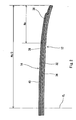
- In Fig. 1, a vertical direction is set to be a radial direction of a
tire 2, a transverse direction is set to be an axial direction of thetire 2, and a perpendicular direction to a paper is set to be a circumferential direction of thetire 2. Thetire 2 takes an almost symmetrical shape about a one-dotted chain line CL in Fig. 1. Thetire 2 comprises a tread 4, asidewall 6, abead 8, acarcass 10, abelt 12, aband 14, aninner liner 16 and achafer 18. - The tread 4 is formed by a crosslinked rubber and takes the shape of an outward convex in the radial direction. The tread 4 forms a
tread surface 20 to come in contact with a road surface. Agroove 22 is provided on thetread surface 20. A tread pattern is formed by thegrooves 22. - The
sidewall 6 is extended almost inward in the radial direction from the end of the tread 4. Thesidewall 6 is formed by a crosslinked rubber. Thesidewall 6 absorbs a shock from the road surface by a flexure. Moreover, thesidewall 6 prevents the external damage of thecarcass 10. - The
bead 8 is extended almost inward in the radial direction from the inside end of thesidewall 6. Thebead 8 is constituted by acore 24 and anapex 26 extended outward in the radial direction from thecore 24. Thecore 24 is ring-shaped and includes a plurality of non-extensible wires (typically, wires formed of steel). Theapex 26 is outward tapered in the radial direction and is formed by a crosslinked rubber having a high hardness. - The
carcass 10 is constituted by afirst carcass ply 28 and asecond carcass ply 30. Thefirst carcass ply 28 and thesecond carcass ply 30 are laid between thebeads 8 on both sides along the insides of the tread 4 and thesidewall 6. The first carcass ply 28 and thesecond carcass ply 30 are wound from an inside toward an outside in the axial direction around thecore 24. - The
first carcass ply 28 and thesecond carcass ply 30 are constituted by a carcass cord and a topping rubber, which is not shown. The absolute value of an angle formed by the carcass cord in the circumferential direction is usually 75 to 90 degrees. In other words, thetire 2 is a radial tire. An organic fiber is usually used for the carcass cord. Examples of a preferable organic fiber include a polyester fiber, a nylon fiber, a rayon fiber, a polyethylene naphthalate fiber (PEN) and an aramid fiber. - The
belt 12 is positioned on an outside in the radial direction of thecarcass 10. Thebelt 12 is provided on thecarcass 10. Thebelt 12 reinforces thecarcass 10. Thebelt 12 is constituted by an inner belt ply 32 and an outer belt ply 34. Each of the inner belt ply 32 and the outer belt ply 34 is constituted by a belt cord and a topping rubber, which is not shown. The belt cord is inclined to the circumferential direction. The direction of inclination to the circumferential direction of the belt cord of the inner belt ply 32 is reverse to the direction of inclination to the circumferential direction of the belt cord of the outer belt ply 34. The preferable material of the belt cord is steel. An organic fiber may be used for the belt cord. - The
inner liner 16 is bonded to the inner peripheral surface of thecarcass 10. Theinner liner 16 is formed by a crosslinked rubber. A rubber having a small air transmittance is used for theinner liner 16. Theinner liner 16 plays a part in holding the internal pressure of thetire 2. - The
chafer 18 is positioned in the vicinity of thebead 8. When thetire 2 is incorporated in a rim, thechafer 18 abuts on the rim. By the abutment, the vicinity of thebead 8 is protected. Thechafer 18 is usually constituted by a cloth and a rubber impregnated into the cloth. It is also possible to use thechafer 18 formed by a single rubber. - Fig. 2 is an enlarged sectional view showing a part of the
belt 12 and theband 14 of thetire 2 in Fig. 1. Theband 14 is constituted by aband ply 36. The band ply 36 covers thewhole belt 12. The band ply 36 is a so-called full ply. The band ply 36 includes aside portion 38 and acenter portion 40. Theside portion 38 is positioned in the vicinity of the edge of thebelt 12. Thecenter portion 40 is positioned in the vicinity of a center in the axial direction of thetire 2. - Fig. 3 is an enlarged exploded perspective view showing the
side portion 38 and thecenter portion 40 of the band ply 36 in Fig. 2. In Fig. 3, an X direction indicates the axial direction, a Y direction indicates the circumferential direction, and a Z direction indicates the radial direction. - The
side portion 38 is constituted by aband cord 42S and a toppingrubber 44S. Theband cord 42S is wound spirally. Theband cord 42S is exactly jointless. Theband cord 42S is extended substantially in the circumferential direction. As described above, theband cord 42S is wound spirally. Therefore, theband cord 42S is strictly inclined slightly to the circumferential direction. The absolute value of an angle formed by theband cord 42S in the circumferential direction is smaller than 2.0 degrees. In the present invention, a direction in which the absolute value of an angle in the circumferential direction is smaller than 2.0 degrees is set to be a "substantial circumferential direction". - The
band cord 42S having a high modulus Ms is used in theside portion 38. Accordingly, the binding force of theside portion 38 to the vicinity of the edge of thebelt 12 is great. By the great binding force, a road noise is suppressed. In particular, a noise having a frequency in a middle range is suppressed. Thetire 2 has an excellent silence. - The
center portion 40 is constituted by aband cord 42C and a toppingrubber 44C. Theband cord 42C is wound spirally. Theband cord 42C is exactly jointless. Theband cord 42C is also extended substantially in the circumferential direction in the same manner as theband cord 42S of theside portion 38. - The
band cord 42C having a low modulus Mc is used in thecenter portion 40. Accordingly, the binding force of thecenter portion 40 to the vicinity of the center of thebelt 12 is comparatively small. The stiffness of the vicinity of the center of thetire 2 including thecenter portion 40 is comparatively small. Thetire 2 has an excellent ride comfort. Theband cord 42C having the low modulus Mc also contributes to a reduction in an exterior noise and a decrease in a rolling resistance. - In respect of the compatibility of the silence obtained by the
side portion 38 with the ride comfort obtained by thecenter portion 40, it is preferable that a ratio (Ms/Mc) of the modulus Ms of theband cord 42S to the modulus Mc of theband cord 42C should be 2.0 to 4.0. The ratio (Ms/Mc) is more preferably 2.3 and is particularly preferably equal to or higher than 2.6. The ratio (Ms/Mc) is more preferably equal to or lower than 3.8 and is particularly preferably equal to or lower than 3.7. In the present invention, the ratio (Ms/Mc) is calculated based on the moduli Ms and Mc obtained when an elongation percentage is 2%. The moduli Ms and Mc are measured in accordance with the rules of "JIS L 1017". - In respect of a reduction in the road noise, the modulus Ms of the
band cord 42S of theside portion 38 is preferably equal to or higher than 3000 N/mm2 and is more preferably equal to or higher than 5000 N/mm2. If the modulus Ms is excessively high, a handling stability is impeded, and furthermore, a rolling resistance is increased. From this viewpoint, the modulus Ms is preferably equal to or lower than 8000 N/mm2, is more preferably equal to or lower than 7500 N/mm2, and is particularly preferably equal to or lower than 7000 N/mm2. - An organic fiber can be suitably used for the
band cord 42S. Examples of the preferable material of theband cord 42S include a polyethylene naphthalate (PEN) fiber and an aramid fiber. The composite of a nylon fiber and the aramid fiber may be used for theband cord 42S. The composite contributes to a reduction in a road noise, an enhancement in a handling stability and a decrease in a rolling resistance. The ratio of the weights of the nylon fiber and the aramid fiber in the composite is preferably 1/4 to 4/1 and more preferably 2/3 to 3/2. - In respect of an enhancement in a ride comfort, a reduction in an exterior noise and a decrease in a rolling resistance, the modulus Mc of the
band cord 42C in thecenter portion 40 is preferably equal to or lower than 2500 N/mm2 and is more preferably equal to or lower than 2200 N/mm2. If the modulus Mc is excessively low, the durability of thetire 2 becomes insufficient. From this viewpoint, the modulus Mc is preferably equal to or higher than 1000 N/mm2and is more preferably equal to or higher than 1500 N/mm2. - An organic fiber can be suitably used for the
band cord 42C. Typically, a nylon fiber is used for theband cord 42C. A polyester fiber or a vinylon fiber may be used for theband cord 42C. - It is preferable that the densities of the
band cords band cords - In Fig. 2, an arrow Ws indicates the width of the
side portion 38 and an arrow Wb/2 indicates a half of the width of theband 14. It is preferable that a ratio of the width Ws of theside portion 38 to the width Wb of theband 14 should be 5.0% to 20.0%. In some cases in which the ratio is lower than the range, the road noise cannot be suppressed sufficiently. From this viewpoint, the ratio is more preferably equal to or higher than 12% and is particularly preferably equal to or higher than 15%. In some cases in which the ratio exceeds the range, the ride comfort becomes insufficient and the rolling resistance is increased, and furthermore, the exterior noise is increased. From this viewpoint, the ratio is more preferably equal to or lower than 19% and is particularly preferably equal to or lower than 18%. - The tire may comprise two full plies or more. In this case, a side portion and a center portion are provided in at least one full ply.
- In the present invention, the dimension of each portion of the
tire 2 is measured in a state in which thetire 2 is incorporated in a normal rim and air is filled to obtain a normal internal pressure. In this specification, the normal rim implies a rim determined in rules on which thetire 2 depends. A "standard rim" in the JATMA rules, a "Design Rim" in the TRA rules and a "Measuring Rim" in the ETRTO rules are included in the normal rim. In this specification, the normal internal pressure implies an internal pressure determined in the rules on which thetire 2 depends. A "maximum air pressure" in the JATMA rules, a "maximum value" described in "TIRE LOAD LIMITS AT VARIOUS COLD INFLATION PRESSURES" in the TRA rules and an "INFLATION PRESSURE" in the ETRTO rules are included in the normal internal pressure. The normal internal pressure of a tire for a car in accordance with the JATMA rules is 180 kPa. - Fig. 4 is a sectional view showing a part of a
pneumatic tire 45 according to another embodiment of the present invention. Fig. 4 shows abelt 46 and aband 48. Thebelt 46 is formed by an inner belt ply 50 and an outer belt ply 52. Thetire 45 comprises the same tread, sidewall, bead, carcass, inner liner and chafer as those in thetire 2 of Fig. 1, which is not shown. - As shown in Fig. 4, the
band 48 is formed by anedge ply 54 and afull ply 56. In thetire 45, the edge ply 54 constitutes aside portion 58. A portion of thefull ply 56 which does not overlap with theside portion 58 constitutes acenter portion 60. Theside portion 58 is positioned in the vicinity of the edge of thebelt 46. Thecenter portion 60 is positioned in the vicinity of a center in the axial direction of thetire 45. - The
side portion 58 and thecenter portion 60 are formed by a band cord and a topping rubber, which is not shown. The band cord is wound spirally. The band cord is exactly jointless. The band cord is extended substantially in a circumferential direction. - A band cord having a high modulus Ms is used in the
side portion 58. Accordingly, the binding force of theside portion 58 to the vicinity of the edge of thebelt 46 is great. By the great binding force, a road noise is suppressed. In particular, a noise having a frequency in a middle range is suppressed. Thetire 45 has an excellent silence. - A band cord having a low modulus Mc is used in the
center portion 60. Accordingly, the binding force of thecenter portion 60 to the vicinity of the center of thebelt 46 is comparatively small. The stiffness of the vicinity of the center of thetire 45 including thecenter portion 60 is comparatively small. Thetire 45 has an excellent ride comfort. The band cord having the low modulus Mc also contributes to a reduction in an exterior noise and a decrease in a rolling resistance. - In respect of the compatibility of the silence obtained by the
side portion 58 with the ride comfort obtained by thecenter portion 60, it is preferable that a ratio (Ms/Mc) of the modulus Ms to the modulus Mc should be 2.0 to 4.0. The ratio (Ms/Mc) is more preferably 2.3 and is particularly preferably equal to or greater than 2.6. The ratio (Ms/Mc) is more preferably equal to or lower than 3.8 and is particularly preferably equal to or lower than 3.7. - In respect of a reduction in the road noise, the modulus Ms of the band cord of the
side portion 58 is preferably equal to or higher than 3000 N/mm2 and is more preferably equal to or higher than 5000 N/mm2. If the modulus Ms is excessively high, a handling stability is impeded, and furthermore, a rolling resistance is increased. From this viewpoint, the modulus Ms is preferably equal to or lower than 8000 N/mm2, is more preferably equal to or lower than 7500 N/mm2, and is particularly preferably equal to or lower than 7000 N/mm2. - An organic fiber can be suitably used for the band cord of the
side portion 58. Examples of the preferable organic fiber include a polyethylene naphthalate fiber and an aramid fiber. The composite of a nylon fiber and the aramid fiber may be used for the band cord of theside portion 58. The composite contributes to a reduction in a road noise, an enhancement in a handling stability and a decrease in a rolling resistance. The ratio of the weights of the nylon fiber and the aramid fiber in the composite is preferably 1/4 to 4/1 and more preferably 2/3 to 3/2. - In respect of an enhancement in a ride comfort, a reduction in an exterior noise and a decrease in a rolling resistance, the modulus Mc of the band cord of the
center portion 60 is preferably equal to or lower than 2500 N/mm2 and is more preferably equal to or lower than 2200 N/mm2. If the modulus Mc is excessively low, the durability of thetire 45 becomes insufficient. From this viewpoint, the modulus Mc is preferably equal to or higher than 1000 N/mm2 and is more preferably equal to or higher than 1500 N/mm2. - An organic fiber can be suitably used for the band cord of the
center portion 60. Typically, a nylon fiber is used. A polyester fiber or a vinylon fiber may be used for aband cord 42C of thecenter portion 60. - It is preferable that the densities of the band cords in the edge ply 54 and the
full ply 56 should be 5 ends/cm to 20 ends/cm. It is preferable that the sectional areas of the band cords in the edge ply 54 and thefull ply 56 should be 0.10 mm2 to 1.6 mm2. - It is preferable that a ratio of a width Ws of the
side portion 58 to a width Wb of theband 48 should be 5.0% to 20.0%. In some cases in which the ratio is lower than the range, the road noise cannot be suppressed sufficiently. From this viewpoint, the ratio is more preferably equal to or higher than 12% and is particularly preferably equal to or higher than 15%. In some cases in which the ratio exceeds the range, the ride comfort becomes insufficient and the rolling resistance is increased, and furthermore, the exterior noise is increased. From this viewpoint, it is more preferable that the ratio should be equal to or lower than 18%. - The tire may comprise two or more edge plies in each of edges on left and right sides. In this case, at least one edge ply having a higher modulus Ms than the modulus Mc of the band cord of the center portion is provided in each of the edges on the left and right sides.
- A pneumatic tire for a passenger car which has a structure shown in Figs. 1 to 3 was obtained. The details of the band of the tire are shown in the following Table 1. In the tire, an angle in a circumferential direction which is formed by the belt cord of an inner belt ply is +24 degrees and an angle in the circumferential direction which is formed by the belt cord of an outer belt ply is -24 degrees. The tire has a size of "215/60R16 95H".
- A tire according to each of examples 2 to 12 and comparative examples 1 to 4 was obtained in the same manner as in the example 1 except that the specifications of a band were set as shown in the following Tables 1 and 2.
- A tire was incorporated in a rim of "16 x 6.5 - JJ" and the internal pressure of the tire was set to be 230 kPa. The tire was attached to a passenger car with front side engine and front wheel drive which has a engine displacement of 2300cm3. The car was caused to run at a speed of 50 km/h over an asphalt road surface having a high roughness. A volume (an overall value) in the right ear of a driver and an exterior volume in the running were measured. Based on the comparative example 1, an evaluation was carried out. Referring to the examples 1 to 12 and the comparative examples 2 to 4, a value was calculated by subtracting a volume according to the comparative example 1 from each of volumes. This result is shown in the following Tables 1 and 2.
- The driver of the car was caused to evaluate a handling stability and a ride comfort at a maximum of 10 points. This result is shown in the following Tables 1 and 2.
- The tire was attached to a rolling resistance testing machine. A load of 4400 N was applied to the tire and a rolling resistance was measured at a speed of 80 km/h. This result is shown in the following Tables 1 and 2 as an index in the case in which a rolling resistance according to the comparative example 1 is set to be 100.
Table 1 Result of Evaluation Compara. example 1 Compara. example 2 Compara. example 3 Example 1 Example 2 Example 3 Example 4 Example 5 Compara. example 4 Side portion Material Nylon PEN PEN PEN PEN PEN PEN PEN PEN Modulus Ms (N/mm2) 1950 12590 12590 12590 12590 12590 12590 12590 12590 Width Ws (mm) 35.0 35.0 35.0 30.0 25.0 20.0 15.0 10.0 5.0 Center portion Material Nylon Nylon PEN Nylon Nylon Nylon Nylon Nylon Nylon Modulus Mc (N/mm2) 1950 1950 12590 1950 1950 1950 1950 1950 1950 Width Wb-Ws·2 (mm) 100.0 100.0 100.0 110.0 120.0 130.0 140.0 150.0 160.0 Ratio Ms/Mc 1.00 6.46 1.00 6.46 6.46 6.46 6.46 6.46 6.46 (Ws/Wb) · 100 (%) 20. 6 20. 6 20. 6 17.6 14.7 11.8 8.8 5.9 2.9 Road noise (dB (A) ) base -1.9 -2.0 -1.8 -1.7 -1.7 -1.5 -1.5 -0.8 Exterior noise (dB (A) ) base +0.5 +1.2 +0.3 +0.2 ±0 ±0 ±0 ±0 Rolling resistance (index) 100 103 110 101 101 100 100 100 100 Handling stability (index) 6 7 7 7 7 7 7 6 6 Ride comfort (index) 6 5 4 6 6 6 6 6 6 Table 2 Result of Evaluation Example 6 Example 7 Example 8 Example 9 Example 10 Example 11 Example 12 Side portion Material Composite Composite Composite Nylon Composite Composite Composite Modulus Ms (N/mm2) 6900 6200 5400 3230 7600 8200 9000 Width Ws (mm) 30 30 30 30 30 30 30 Center portion Material Nylon Nylon Nylon Nylon Nylon Nylon Nylon Modulus Mc (N/mm2) 1950 1950 1950 1950 1950 1950 1950 Width Wb-Ws·2 (mm) 110.0 110.0 110.0 110.0 110.0 110.0 110.0 Ratio Ms/Mc 3.54 3.18 2.77 1.66 3.90 4.21 4.62 (Ws/Wb) · 100 (%) 17.6 17.6 17.6 17. 6 17. 6 17.6 17.6 Road noise (dB (A) ) -1. 7 -1. 6 -1. 6 -0.5 -1.7 -1.7 -1. 7 Exterior noise (dB (A) ) ±0 -0. 1 -0. 2 -0. 1 +0.1 +0. 3 +0. 3 Rolling resistance (index) 100 99 98 99 100 100 101 Handling stability (index) 7 7 7 6 7 7 7 Ride comfort (index) 6 7 7 6 6 6 6 - As shown in the Tables 1 and 2, the tire according to each of the examples is excellent in all of a silence, a rolling resistance, a handling stability and a ride comfort. From the results of the evaluation, the advantages of the present invention are apparent.
- The above description is only illustrative and various changes can be made without departing from the scope of the present invention as defined by the appended claims.
Claims (6)
- A pneumatic tire (2) comprising a tread (4) having an external surface forming a tread surface (20), a pair of sidewalls (6) extended almost inward in a radial direction from both ends of the tread, a pair of beads (8) extended almost inward in the radial direction from the sidewalls, a carcass (10) laid between both of the beads along insides of the tread and the sidewalls, a belt (12) provides on the carcass at an inside in the radial direction of the tread, and a band (14) positioned between the belt and the tread and covering the belt,
the band ply (36) constituting the band (14) being formed by a band cord (42s,42c) and a topping rubber (44s,44c), characterized in that
the band ply includes a side portion (38) positioned in the vicinity of an edge of the belt and a center portion (40) positioned in the vicinity of a center in an axial direction,
a modulus of the band cord of the side portion (Ms) is higher than that of the band cord of the center portion (Mc), and
a width Ws of the side portion is 5.0% to 20.0% of a width Wb of the band. - The tire according to claim 1, wherein a ratio of the modulus of the band cord of the side portion to that of the band cord of the center portion is 2.0 to 4.0.
- The tire according to claim 1, wherein the width Ws of the side portion is 12.0% to 18.0% of the width Wb of the band.
- The tire according to claim 1, wherein the modulus of the band cord of the side portion is 2.6 to 3.7 times as high as that of the band cord of the center portion.
- The tire according to claim 1, wherein the modulus of the band cord of the side portion is 3000 N/mm2 to 8000 N/mm2.
- The tire according to claim 5, wherein a composite of a nylon fiber and an aramid fiber is used for the band cord of the side portion.
Applications Claiming Priority (2)
| Application Number | Priority Date | Filing Date | Title |
|---|---|---|---|
| JP2004081803A JP4723198B2 (en) | 2004-03-22 | 2004-03-22 | Pneumatic tire |
| JP2004081803 | 2004-03-22 |
Publications (2)
| Publication Number | Publication Date |
|---|---|
| EP1580030A1 EP1580030A1 (en) | 2005-09-28 |
| EP1580030B1 true EP1580030B1 (en) | 2006-09-20 |
Family
ID=34858360
Family Applications (1)
| Application Number | Title | Priority Date | Filing Date |
|---|---|---|---|
| EP05001052A Ceased EP1580030B1 (en) | 2004-03-22 | 2005-01-19 | Pneumatic tire |
Country Status (5)
| Country | Link |
|---|---|
| US (1) | US7165588B2 (en) |
| EP (1) | EP1580030B1 (en) |
| JP (1) | JP4723198B2 (en) |
| CN (1) | CN100497008C (en) |
| DE (1) | DE602005000138T2 (en) |
Cited By (4)
| Publication number | Priority date | Publication date | Assignee | Title |
|---|---|---|---|---|
| EP2829420A1 (en) | 2013-07-26 | 2015-01-28 | Continental Reifen Deutschland GmbH | Pneumatic tyres for a vehicle |
| EP2829419A1 (en) | 2013-07-26 | 2015-01-28 | Continental Reifen Deutschland GmbH | Pneumatic tyres for a vehicle |
| DE102014220518A1 (en) | 2014-10-09 | 2016-04-14 | Continental Reifen Deutschland Gmbh | Pneumatic vehicle tire having a belt bandage |
| DE102017215655A1 (en) | 2017-09-06 | 2019-03-07 | Continental Reifen Deutschland Gmbh | Pneumatic vehicle tire having a belt bandage |
Families Citing this family (14)
| Publication number | Priority date | Publication date | Assignee | Title |
|---|---|---|---|---|
| JP4908101B2 (en) * | 2005-11-25 | 2012-04-04 | 株式会社ブリヂストン | Pneumatic tire |
| JP4478646B2 (en) * | 2005-12-21 | 2010-06-09 | 住友ゴム工業株式会社 | Pneumatic tire |
| DE102006022670A1 (en) | 2006-05-16 | 2007-11-22 | Continental Aktiengesellschaft | Vehicle tires |
| JP5005978B2 (en) * | 2006-07-28 | 2012-08-22 | 住友ゴム工業株式会社 | Run flat tire |
| DE102007005281A1 (en) * | 2007-02-02 | 2008-08-07 | Continental Aktiengesellschaft | Reinforcing layer of hybrid cords for elastomeric products, in particular for the belt bandage of pneumatic vehicle tires |
| JP4377933B2 (en) * | 2007-08-03 | 2009-12-02 | 住友ゴム工業株式会社 | Pneumatic tire |
| JP4377934B2 (en) * | 2007-08-03 | 2009-12-02 | 住友ゴム工業株式会社 | Pneumatic tire |
| JP4295795B2 (en) | 2007-12-07 | 2009-07-15 | 住友ゴム工業株式会社 | Pneumatic tire |
| JP5353272B2 (en) * | 2009-02-02 | 2013-11-27 | 横浜ゴム株式会社 | Pneumatic radial tire |
| JP5353275B2 (en) * | 2009-02-03 | 2013-11-27 | 横浜ゴム株式会社 | Pneumatic radial tire |
| JP5685047B2 (en) * | 2010-10-15 | 2015-03-18 | 住友ゴム工業株式会社 | Pneumatic tire |
| US9038682B2 (en) * | 2011-08-10 | 2015-05-26 | The Yokohama Rubber Co., Ltd. | Pneumatic tire |
| DE112011105656B4 (en) * | 2011-09-22 | 2016-02-18 | The Yokohama Rubber Co., Ltd. | tire |
| MX2017016678A (en) * | 2016-10-13 | 2018-09-12 | Kordsa Teknik Tekstil As | Nylon 6.6 cap ply. |
Family Cites Families (11)
| Publication number | Priority date | Publication date | Assignee | Title |
|---|---|---|---|---|
| JPH0382605A (en) * | 1989-08-25 | 1991-04-08 | Toyo Tire & Rubber Co Ltd | Radial tire |
| JP2788655B2 (en) * | 1989-10-13 | 1998-08-20 | 住友ゴム工業 株式会社 | Motorcycle tires |
| JP2648652B2 (en) * | 1992-06-10 | 1997-09-03 | 住友ゴム工業株式会社 | Pneumatic radial tire |
| JPH0624206A (en) * | 1992-07-09 | 1994-02-01 | Sumitomo Rubber Ind Ltd | Radial tires for light trucks |
| DE69509323T2 (en) * | 1994-08-23 | 1999-08-26 | Dunlop Gmbh | Pneumatic vehicle tires |
| JP3113592B2 (en) * | 1996-02-15 | 2000-12-04 | 住友ゴム工業株式会社 | Pneumatic radial tire |
| JP4275210B2 (en) * | 1998-01-27 | 2009-06-10 | 株式会社ブリヂストン | Radial tire |
| JP3993378B2 (en) * | 2000-11-01 | 2007-10-17 | 住友ゴム工業株式会社 | Pneumatic radial tire |
| CN100467290C (en) * | 2001-06-13 | 2009-03-11 | 住友橡胶工业株式会社 | Pneumatic radial tire |
| JP2003320813A (en) * | 2002-05-07 | 2003-11-11 | Bridgestone Corp | Pneumatic tire |
| JP3950088B2 (en) * | 2003-07-24 | 2007-07-25 | 住友ゴム工業株式会社 | Pneumatic radial tire |
-
2004
- 2004-03-22 JP JP2004081803A patent/JP4723198B2/en not_active Expired - Fee Related
-
2005
- 2005-01-19 DE DE602005000138T patent/DE602005000138T2/en not_active Expired - Lifetime
- 2005-01-19 EP EP05001052A patent/EP1580030B1/en not_active Ceased
- 2005-01-28 US US11/043,958 patent/US7165588B2/en not_active Expired - Fee Related
- 2005-02-05 CN CNB2005100083202A patent/CN100497008C/en not_active Expired - Fee Related
Cited By (6)
| Publication number | Priority date | Publication date | Assignee | Title |
|---|---|---|---|---|
| EP2829420A1 (en) | 2013-07-26 | 2015-01-28 | Continental Reifen Deutschland GmbH | Pneumatic tyres for a vehicle |
| EP2829419A1 (en) | 2013-07-26 | 2015-01-28 | Continental Reifen Deutschland GmbH | Pneumatic tyres for a vehicle |
| DE102013108052A1 (en) | 2013-07-26 | 2015-01-29 | Continental Reifen Deutschland Gmbh | Vehicle tires |
| DE102013108051A1 (en) | 2013-07-26 | 2015-01-29 | Continental Reifen Deutschland Gmbh | Vehicle tires |
| DE102014220518A1 (en) | 2014-10-09 | 2016-04-14 | Continental Reifen Deutschland Gmbh | Pneumatic vehicle tire having a belt bandage |
| DE102017215655A1 (en) | 2017-09-06 | 2019-03-07 | Continental Reifen Deutschland Gmbh | Pneumatic vehicle tire having a belt bandage |
Also Published As
| Publication number | Publication date |
|---|---|
| EP1580030A1 (en) | 2005-09-28 |
| US20050205189A1 (en) | 2005-09-22 |
| US7165588B2 (en) | 2007-01-23 |
| JP4723198B2 (en) | 2011-07-13 |
| DE602005000138T2 (en) | 2007-09-06 |
| JP2005263137A (en) | 2005-09-29 |
| CN1672964A (en) | 2005-09-28 |
| DE602005000138D1 (en) | 2006-11-02 |
| CN100497008C (en) | 2009-06-10 |
Similar Documents
| Publication | Publication Date | Title |
|---|---|---|
| EP1580030B1 (en) | Pneumatic tire | |
| EP2186656B1 (en) | Pneumatic tire | |
| EP2332744A2 (en) | Pneumatic tire | |
| EP1683654B1 (en) | Runflat tire | |
| EP1987963A2 (en) | Tire for motorcycle | |
| EP1215054B1 (en) | Pneumatic tire | |
| EP1859961B1 (en) | Pneumatic tire for motorcycle | |
| EP2543522B1 (en) | Two-wheeled automotive vehicle tire | |
| EP2275285B1 (en) | Pneumatic tire | |
| EP1580038B1 (en) | Run-flat tire | |
| EP2261060B1 (en) | Motorcycle tire | |
| EP1800904B1 (en) | Pneumatic tire | |
| EP2193933A1 (en) | Pneumatic tire | |
| JP2005193865A (en) | Pneumatic radial tire | |
| JP4583891B2 (en) | Motorcycle tires | |
| EP1785286B1 (en) | Pneumatic tire for motorcycle | |
| EP1642752B1 (en) | Radial tyre for motorcycle | |
| EP1488939B1 (en) | Pneumatic tire | |
| EP1772294B1 (en) | Tire for motorcycle | |
| JP5005978B2 (en) | Run flat tire | |
| JP4515124B2 (en) | Pneumatic tire | |
| JP4410545B2 (en) | Method for manufacturing motorcycle tire | |
| JP4478481B2 (en) | Pneumatic tire | |
| JP2024023080A (en) | Pneumatic radial tires for passenger cars | |
| JP2003231401A (en) | Motorcycle tires |
Legal Events
| Date | Code | Title | Description |
|---|---|---|---|
| PUAI | Public reference made under article 153(3) epc to a published international application that has entered the european phase |
Free format text: ORIGINAL CODE: 0009012 |
|
| AK | Designated contracting states |
Kind code of ref document: A1 Designated state(s): AT BE BG CH CY CZ DE DK EE ES FI FR GB GR HU IE IS IT LI LT LU MC NL PL PT RO SE SI SK TR |
|
| AX | Request for extension of the european patent |
Extension state: AL BA HR LV MK YU |
|
| 17P | Request for examination filed |
Effective date: 20051110 |
|
| GRAP | Despatch of communication of intention to grant a patent |
Free format text: ORIGINAL CODE: EPIDOSNIGR1 |
|
| AKX | Designation fees paid |
Designated state(s): DE FR GB |
|
| GRAS | Grant fee paid |
Free format text: ORIGINAL CODE: EPIDOSNIGR3 |
|
| GRAA | (expected) grant |
Free format text: ORIGINAL CODE: 0009210 |
|
| AK | Designated contracting states |
Kind code of ref document: B1 Designated state(s): DE FR GB |
|
| REG | Reference to a national code |
Ref country code: GB Ref legal event code: FG4D |
|
| REF | Corresponds to: |
Ref document number: 602005000138 Country of ref document: DE Date of ref document: 20061102 Kind code of ref document: P |
|
| ET | Fr: translation filed | ||
| PLBE | No opposition filed within time limit |
Free format text: ORIGINAL CODE: 0009261 |
|
| STAA | Information on the status of an ep patent application or granted ep patent |
Free format text: STATUS: NO OPPOSITION FILED WITHIN TIME LIMIT |
|
| 26N | No opposition filed |
Effective date: 20070621 |
|
| REG | Reference to a national code |
Ref country code: FR Ref legal event code: PLFP Year of fee payment: 12 |
|
| REG | Reference to a national code |
Ref country code: FR Ref legal event code: PLFP Year of fee payment: 13 |
|
| PGFP | Annual fee paid to national office [announced via postgrant information from national office to epo] |
Ref country code: GB Payment date: 20170118 Year of fee payment: 13 |
|
| REG | Reference to a national code |
Ref country code: FR Ref legal event code: PLFP Year of fee payment: 14 |
|
| PGFP | Annual fee paid to national office [announced via postgrant information from national office to epo] |
Ref country code: FR Payment date: 20171211 Year of fee payment: 14 |
|
| GBPC | Gb: european patent ceased through non-payment of renewal fee |
Effective date: 20180119 |
|
| PG25 | Lapsed in a contracting state [announced via postgrant information from national office to epo] |
Ref country code: GB Free format text: LAPSE BECAUSE OF NON-PAYMENT OF DUE FEES Effective date: 20180119 |
|
| PG25 | Lapsed in a contracting state [announced via postgrant information from national office to epo] |
Ref country code: FR Free format text: LAPSE BECAUSE OF NON-PAYMENT OF DUE FEES Effective date: 20190131 |
|
| PGFP | Annual fee paid to national office [announced via postgrant information from national office to epo] |
Ref country code: DE Payment date: 20211130 Year of fee payment: 18 |
|
| REG | Reference to a national code |
Ref country code: DE Ref legal event code: R119 Ref document number: 602005000138 Country of ref document: DE |
|
| PG25 | Lapsed in a contracting state [announced via postgrant information from national office to epo] |
Ref country code: DE Free format text: LAPSE BECAUSE OF NON-PAYMENT OF DUE FEES Effective date: 20230801 |