EP1580029A1 - Pneumatic tire - Google Patents
Pneumatic tire Download PDFInfo
- Publication number
- EP1580029A1 EP1580029A1 EP05002185A EP05002185A EP1580029A1 EP 1580029 A1 EP1580029 A1 EP 1580029A1 EP 05002185 A EP05002185 A EP 05002185A EP 05002185 A EP05002185 A EP 05002185A EP 1580029 A1 EP1580029 A1 EP 1580029A1
- Authority
- EP
- European Patent Office
- Prior art keywords
- topping
- belt
- pneumatic tire
- topping rubber
- rubber layer
- Prior art date
- Legal status (The legal status is an assumption and is not a legal conclusion. Google has not performed a legal analysis and makes no representation as to the accuracy of the status listed.)
- Granted
Links
- 229920001971 elastomer Polymers 0.000 claims abstract description 65
- 239000005060 rubber Substances 0.000 claims abstract description 65
- 239000002131 composite material Substances 0.000 claims abstract description 20
- 239000011324 bead Substances 0.000 claims abstract description 11
- 238000000034 method Methods 0.000 description 8
- 230000001965 increasing effect Effects 0.000 description 6
- 229910000831 Steel Inorganic materials 0.000 description 4
- 239000010959 steel Substances 0.000 description 4
- 230000000694 effects Effects 0.000 description 3
- 238000012360 testing method Methods 0.000 description 3
- 229920000297 Rayon Polymers 0.000 description 2
- 239000004760 aramid Substances 0.000 description 2
- 229920003235 aromatic polyamide Polymers 0.000 description 2
- 239000000835 fiber Substances 0.000 description 2
- 238000005259 measurement Methods 0.000 description 2
- 239000002964 rayon Substances 0.000 description 2
- 229920001875 Ebonite Polymers 0.000 description 1
- 239000004677 Nylon Substances 0.000 description 1
- 230000002411 adverse Effects 0.000 description 1
- 150000001875 compounds Chemical class 0.000 description 1
- 239000000470 constituent Substances 0.000 description 1
- 238000007796 conventional method Methods 0.000 description 1
- 238000002788 crimping Methods 0.000 description 1
- 230000002542 deteriorative effect Effects 0.000 description 1
- 230000002708 enhancing effect Effects 0.000 description 1
- 238000011156 evaluation Methods 0.000 description 1
- 239000000463 material Substances 0.000 description 1
- 238000000465 moulding Methods 0.000 description 1
- 229920001778 nylon Polymers 0.000 description 1
- 229920000728 polyester Polymers 0.000 description 1
- 239000007787 solid Substances 0.000 description 1
Images


Classifications
-
- B—PERFORMING OPERATIONS; TRANSPORTING
- B60—VEHICLES IN GENERAL
- B60C—VEHICLE TYRES; TYRE INFLATION; TYRE CHANGING; CONNECTING VALVES TO INFLATABLE ELASTIC BODIES IN GENERAL; DEVICES OR ARRANGEMENTS RELATED TO TYRES
- B60C9/00—Reinforcements or ply arrangement of pneumatic tyres
- B60C9/18—Structure or arrangement of belts or breakers, crown-reinforcing or cushioning layers
- B60C9/20—Structure or arrangement of belts or breakers, crown-reinforcing or cushioning layers built-up from rubberised plies each having all cords arranged substantially parallel
- B60C2009/2061—Physical properties or dimensions of the belt coating rubber
- B60C2009/207—Double layers, e.g. using different rubbers in the same belt ply
-
- Y—GENERAL TAGGING OF NEW TECHNOLOGICAL DEVELOPMENTS; GENERAL TAGGING OF CROSS-SECTIONAL TECHNOLOGIES SPANNING OVER SEVERAL SECTIONS OF THE IPC; TECHNICAL SUBJECTS COVERED BY FORMER USPC CROSS-REFERENCE ART COLLECTIONS [XRACs] AND DIGESTS
- Y10—TECHNICAL SUBJECTS COVERED BY FORMER USPC
- Y10T—TECHNICAL SUBJECTS COVERED BY FORMER US CLASSIFICATION
- Y10T152/00—Resilient tires and wheels
- Y10T152/10—Tires, resilient
- Y10T152/10495—Pneumatic tire or inner tube
- Y10T152/10765—Characterized by belt or breaker structure
- Y10T152/1081—Breaker or belt characterized by the chemical composition or physical properties of elastomer or the like
Definitions
- the present invention relates to a pneumatic tire in which uniformity can be enhanced.
- a pneumatic tire comprises:
- Such a belt ply having the composite topping rubber layer disperses rigidity of the belt ply in the circumferential direction of the tire, and enhances the uniformity, especially the TFV at the time of high speed running.
- a pneumatic tire 1 according to the present invention comprises a tread portion 2, a pair of sidewall portions 3, a pair of bead portions 4, a carcass 6 extending between the bead portions 4 through the tread portion 2 and sidewall portions 3, a belt 7 disposed radially outside the carcass 6 in the tread portion 2.
- the tire 1 in this embodiment is a tubeless radial tire for a passenger car.
- the carcass 6 comprises at least one ply, in this embodiment only one ply 6A, of radially arranged carcass cords extending between the bead portions 4 through the tread portion 2 and sidewall portions 3 and turned up around the bead cores 5 from the axially inside to outside of the tire to be secured thereto and to form a pair of turnup portions 6b and a main portion 6a therebetween.
- the cords are arranged at a certain angle in the range of from 80 to 90 degrees with respect to the tire equator C.
- organic fiber cords e.g. polyester, nylon, rayon, aramid and the like are preferably used.
- steel cords can also be used.
- a bead apex 8 is disposed and extends taperingly radially outwards from the bead core 5.
- the bead apex 8 is made of a hard rubber compound preferably having a JIS-A hardness of 80 to 98 degrees.
- the belt 7 comprises at least one belt ply, preferably two belt plies 7A and 7B as shown in Fig. 1.
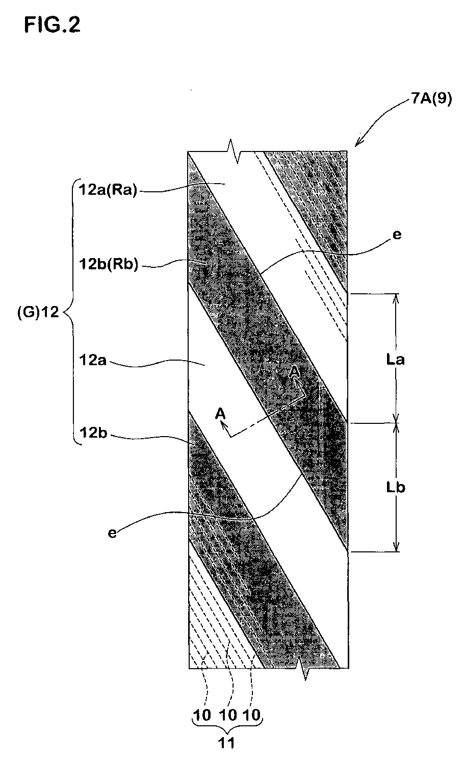
- Fig. 2 is a developed view of the one belt ply 7A.
- the belt ply 7A comprises a plurality of parallel belt cords 11 inclined with respect to a circumferential direction of the tire, and a topping rubber layer G in which the belt cords 11 are embedded.
- steel cords are employed as the belt cords 10.
- the steel cords it is possible to use various cords, such as solid wires, stranded wires, or a plurality of wires bundle in parallel to one another.
- organic fiber cords having high elasticity such as aromatic polyamide, rayon and the like.
- the belt cords 10 are inclined with respect to the tire equator C through about 10 to 35°.
- the belt plies 7A and 7B are arranged in a direction in which the cords intersect with each other.
- the belt ply 7A arranged radially inside of the tire is wider than the belt ply 7B, and widthwise centers of both the plies 7A and 7B are substantially aligned to each other.
- At least one of the belt plies 7A and 7B of the belt 7 comprises a belt ply 9 having a composite topping rubber layer 12.
- each of the belt plies 7A and 7B comprises the belt ply 9 having the layer 12.
- the composite topping rubber layer 12 formed at least two kinds of topping rubbers having different complex elastic moduli and alternately arranged in the circumferential direction of the tire.
- the composite layer 12 of this embodiment comprises a first topping portion 12a made of a first topping rubber Ra and a second topping portion 12b made of a second topping rubber Rb having greater complex elastic modulus than that of the first topping rubber Ra.
- the first topping portion 12a and the second topping portion 12b are alternately arranged in the circumferential direction of the tire. That is, in this embodiment, there are two kinds of topping rubbers.
- Each of the first topping portion 12a and the second topping portion 12b are formed into substantially parallelogram having a pair of parallel sides e, e extending along the cords 11.
- the first and second topping portions 12a and 12b form the topping rubber layer 12 which continuously extends in the circumferential direction of the tire through a joint at which the sides e and e thereof are jointed to each other.
- the topping rubber layer 12 of this embodiment has an enough thickness to completely cover the belt cords 11.
- a thickness t of the topping rubber layer 12 is greater than an outer diameter tc of the belt cord 10.
- the manner in which the topping rubber layer 12 covers the belt cords 11 is not limited to that shown in the drawing.
- the thickness t of the topping rubber layer 12 is preferably about 1.0 to 2.0 times the outer diameter tc of the belt cord 10. This thickness t may be constant or varied.
- the cross sections of the belt plies 7A and 7B are usually finished to the shape as shown in Fig. 3 by crimping thin rubber sheets on both side surfaces of the belt cords 11.
- the first topping portion 12a and the second topping portion 12b constitute the entire thickness as measured from the upper surface to the lower surface of the belt ply 9.
- the belt ply 9 having the composite rubber layer 12 provides rigidity variation in which a high rigidity portion and a low rigidity portion are dispersed in the circumferential direction. This reduces TFV and RFV and enhances the uniformity as in a later-described embodiment.
- the belt ply includes at least one joint portion that is a joint at which both ends of the ply are jointed to each other in the molding process. This joint portion provides a primary vibration peak at the time of high speed rotation. However, if the first and second topping portions 12a and 12b having different rigidities are jointed each other and many joint portions are formed, the vibration peak is dispersed and the uniformity is enhanced.
- the rigidity of the belt 7 can be increased but the riding comfort is deteriorated and noise is increased. Therefore, if the two kinds of rubbers having different elastic moduli are included in the topping rubber layer, the rigidity of the belt 7 can be enhanced without deteriorating the riding comfort and increasing noise.
- the hoop effect of the belt 7 is suitable for suppressing the variation of the FV component, and since the rigidity distribution of the belt ply is varied, there is an effect that the tire noise is reduced and the peak of a particular order component is reduced.
- the two belt plies 7A and 7B are radially arranged in the direction in which the belt cords 11 intersect with each other. Therefore, the two belt plies 9 and 9 having composite topping rubber layers 12 are overlapped in the direction in which the substantially parallelogram topping rubber portions 12a intersect with each other. With this, a new binding force is generated by a cross structure comprising the topping portions 12a and 12b, especially the second rubber Rb having greater complex elastic modulus. Thus, the rigidity as the belt 7 is further enhanced, and the vibration at the time of high speed running can be suppressed.
- the belt ply 9 of this embodiment is formed such that a length La of the first topping portion 12a in the circumferential direction of the tire measured at a side edge thereof in the widthwise direction of the ply, and a length Lb of the second topping portion 12b in the circumferential direction of the tire are substantially equal to each other.
- the first and second topping portions 12a and 12b are formed by parallelograms having the same shapes. According to such a topping rubber layer 12, since the distribution of rigidity is uniform, the uniformity can further be enhanced.
- the lengths La and Lb can be set in accordance with required performance. For example, when it is necessary to further enhance the rigidity of the belt ply 9, it is preferable that the length Lb of the second topping portion 12b is longer than the length La of the first topping portion 12a. When it is necessary to moderate the rigidity of the belt ply 9 on the other hand, the length Lb of the second topping portion 12b should be shorter than the length La of the first topping portion 12a. In any case, it is preferable that the lengths La and Lb are maintained constantly in one belt ply.
- the number of first topping portion 12a and second topping portion 12b is 3 or more and 20 or less, more preferably 5 or more and 15 or less, and more preferably 5 or more and 10 or less. If the number is less than 3, the distribution degree of rigidity is small, and the enhancing effect of the uniformity is small. In some cases, there is an adverse possibility that the uniformity component becomes great. If the number exceeds 20 on the other hand, there is a tendency that the number of joint processes for jointing the first and second topping portions 12a and 12b is increased and the productivity is deteriorated.
- the length of the belt ply 9 is substantially an integral multiple of a sum (La+Lb) of the lengths La and Lb of the first and second topping portions 12a and 12b.
- the reason of the term "substantially” is that the overlapped portion of both ends of the plies is taken into account.
- a ratio (E*2/E*1) of complex elastic modulus E*1 of the first topping rubber Ra and complex elastic modulus E*2 of the second topping rubber Rb of the belt ply 9 is 1.15 or higher. If the ratio (E*2/E*1) is less than 1.15, the rigidity can not be dispersed effectively in the topping grubber 12, and there is a tendency that the uniformity can not be enhanced. It is more preferable that the ratio (E*2/E*1) is 1.2 or higher.
- the ratio (E*2/E*1) is not more than 1.50 and more preferably not more than 1.40. More specifically, the complex elastic modulus of the first topping rubber Ra is preferably about from 5.0 to 8.0 MPa.
- the complex elastic modulus is a value obtained by measuring a measurement sample using a viscoelasticity spectrometer "VES F-3 type" made by Iwamoto Seisakusho under the following conditions:
- the belt ply 9 having the composite topping rubber layer 12 can be produced using equipment or process as shown in Fig. 5.
- Fig. 5 shows a central conveyor Cc, a first ply piece supply conveyor Ca disposed on one side of the central conveyor Cc, and a second ply piece supply conveyor Cb disposed on the other side.
- the first ply piece supply conveyor Ca successively supplies, toward the central conveyor Cc, first topping rubber ply pieces 20a obtained by bias-cutting a base ply (not shown) coated with the first rubber Ra.
- the second ply piece supply conveyor Cb successively supplies, toward the central conveyor Cc, second topping rubber ply pieces 20b obtained by bias-cutting a base ply (not shown) coated with the second rubber Rb.
- the first and second ply pieces 20a and 20b which are alternately supplied are pressed and jointed, thereby continuously forming the long belt plies 9 having the composite topping rubbers.
- This is one example of the producing method, and the method is not limited to this only.
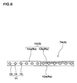
- Fig. 6 shows another embodiment of the present invention.
- Fig. 6 corresponds to a sectional view taken on line A-A in Fig. 2.
- the topping rubber layer 12 of this embodiment only one surface of the belt cords 11 is made of two kinds of topping rubbers Ra and Rb, and the other surface is made of one kind of topping rubber (e.g., first rubber Ra). In this manner, the present invention can be carried out in various modes.
- the topping rubber may be formed of three or more kinds of topping rubbers having different complex elastic moduli.
- three kinds of rubber materials are alternately arranged in the same order in the circumferential direction of the tire.
- pneumatic radial tires (tire size: 215/60R16 95H) were prototyped based on the specification shown in Table 1, and uniformity was tested.
- TFV and RFV were measured in accordance with uniformity testing conditions of JASO C607:2000 using a uniformity tester.
- the evaluation speed is 120 km/h. This is because that TFV which is prone to have a problem as the running speed is increased is evaluated.
- a result is expressed using the average value (N) of twenty tires. The smaller the numeric value, the better the result is. Table 1 shows the test result and the like.
- the example tire of the present invention has smaller TFV and RFV and more excellent uniformity as compared with the conventional example.
Landscapes
- Engineering & Computer Science (AREA)
- Mechanical Engineering (AREA)
- Tires In General (AREA)
Abstract
Description

Claims (7)
- A pneumatic tire comprising:a carcass extending between bead portions through a tread portion and sidewall portions; anda belt disposed radially outside the carcass in the tread portion, said belt comprisingat least one belt ply made of parallel cords embedded in a composite topping rubber layer,said composite topping rubber layer formed at least two kinds of topping rubbers having different complex elastic moduli andsaid topping rubbers alternately disposed in a circumferential direction of the tire.
- A pneumatic tire according to Claim 1, wherein
the composite topping rubber layer comprises
a first topping portion made of a first topping rubber and
a second topping portion made of a second topping rubber having greater complex elastic modulus than that of the first topping rubber. - A pneumatic tire according to Claim 2, wherein
the parallel cords of the belt ply are inclined with respect to the circumferential direction of the tire, and
each of the first topping portion and the second topping portion are formed into substantially parallelogram having a pair of parallel sides extending along the cords. - A pneumatic tire according to Claim 1 or 2, wherein
the belt comprises at least two belt plies arranged in a direction in which the cords intersect with each other, and
each of the belt plies has the composite topping rubber layer. - A pneumatic tire according to Claim 2 or 3, wherein
a length of the first topping portion in the circumferential direction of the tire substantially equals to a length of the second topping portion in the circumferential direction of the tire. - A pneumatic tire according to Claim 2 or 3, wherein
each belt ply having the composite topping rubber layer includes from 3 to 20 first topping portions and second topping portions. - A pneumatic tire according to Claim 2 or 3, wherein
a ratio (E*2/E*1) of complex elastic modulus E*1 of the first topping rubber and complex elastic modulus E*2 of the second topping rubber is from 1.15 to 1.50.
Applications Claiming Priority (2)
| Application Number | Priority Date | Filing Date | Title |
|---|---|---|---|
| JP2004083204 | 2004-03-22 | ||
| JP2004083204A JP4500075B2 (en) | 2004-03-22 | 2004-03-22 | Pneumatic tire |
Publications (2)
| Publication Number | Publication Date |
|---|---|
| EP1580029A1 true EP1580029A1 (en) | 2005-09-28 |
| EP1580029B1 EP1580029B1 (en) | 2006-08-16 |
Family
ID=34858378
Family Applications (1)
| Application Number | Title | Priority Date | Filing Date |
|---|---|---|---|
| EP05002185A Expired - Lifetime EP1580029B1 (en) | 2004-03-22 | 2005-02-02 | Pneumatic tire |
Country Status (5)
| Country | Link |
|---|---|
| US (1) | US7156138B2 (en) |
| EP (1) | EP1580029B1 (en) |
| JP (1) | JP4500075B2 (en) |
| CN (1) | CN100441429C (en) |
| DE (1) | DE602005000068T2 (en) |
Families Citing this family (7)
| Publication number | Priority date | Publication date | Assignee | Title |
|---|---|---|---|---|
| JP5180901B2 (en) * | 2008-07-10 | 2013-04-10 | 住友ゴム工業株式会社 | Pneumatic tire design method |
| KR101472597B1 (en) * | 2008-08-07 | 2014-12-15 | 스미도모 고무 고교 가부시기가이샤 | tire |
| JP5173674B2 (en) * | 2008-08-22 | 2013-04-03 | 住友ゴム工業株式会社 | Pneumatic tire |
| KR20130009974A (en) * | 2010-02-24 | 2013-01-24 | 스미토모 고무 고교 가부시키가이샤 | Manufacturing method for pneumatic tire |
| JP5946387B2 (en) * | 2012-10-11 | 2016-07-06 | 東洋ゴム工業株式会社 | Rubber wet masterbatch |
| JP7820902B2 (en) * | 2019-10-29 | 2026-02-26 | 住友ゴム工業株式会社 | tire |
| JP2024023084A (en) * | 2022-08-08 | 2024-02-21 | 株式会社ブリヂストン | Pneumatic radial tires for passenger cars |
Citations (1)
| Publication number | Priority date | Publication date | Assignee | Title |
|---|---|---|---|---|
| JP2003226113A (en) * | 2002-02-06 | 2003-08-12 | Sumitomo Rubber Ind Ltd | Pneumatic tire |
Family Cites Families (15)
| Publication number | Priority date | Publication date | Assignee | Title |
|---|---|---|---|---|
| DE69110954T2 (en) * | 1990-04-18 | 1995-11-23 | Sumitomo Rubber Ind | Belted pneumatic tires for motorcycles and manufacturing methods. |
| JPH0747806A (en) * | 1993-08-06 | 1995-02-21 | Sumitomo Rubber Ind Ltd | Pneumatic tire |
| JPH07186614A (en) * | 1993-12-27 | 1995-07-25 | Bridgestone Corp | Pneumatic radial tire |
| JPH0872160A (en) * | 1994-09-09 | 1996-03-19 | Ohtsu Tire & Rubber Co Ltd :The | Cord-containing rubber sheet |
| JPH1199564A (en) * | 1997-09-26 | 1999-04-13 | Yokohama Rubber Co Ltd:The | Pneumatic radial tire and production thereof |
| FR2789941B1 (en) * | 1999-02-19 | 2001-04-06 | Michelin Soc Tech | REINFORCEMENT TAPE FOR TIRE, MANUFACTURING METHOD THEREOF, AND TIRE MANUFACTURING METHOD |
| JP2001121622A (en) * | 1999-10-25 | 2001-05-08 | Bridgestone Corp | Method and device for manufacturing joint body of strip piece |
| EP1095795B1 (en) * | 1999-10-28 | 2006-09-06 | Pirelli Tyre S.p.A. | Low rolling resistance tire for vehicles |
| JP4502486B2 (en) * | 2000-09-11 | 2010-07-14 | 株式会社ブリヂストン | Aircraft pneumatic tire |
| JP4903944B2 (en) * | 2001-03-27 | 2012-03-28 | 住友ゴム工業株式会社 | Method for forming tire constituent member |
| JP2002326289A (en) * | 2001-05-02 | 2002-11-12 | Bridgestone Corp | Pneumatic tire and method for manufacturing the same |
| JP2003034109A (en) * | 2001-07-23 | 2003-02-04 | Sumitomo Rubber Ind Ltd | Motorcycle tire and method of manufacturing the same |
| DE60316369T2 (en) * | 2002-02-14 | 2008-06-12 | Sumitomo Rubber Industries Ltd., Kobe | tire |
| AU2003238423A1 (en) * | 2002-06-03 | 2003-12-19 | Mechelin Recherche Et Technique S.A. | System for producing a reinforcing structure for a tyre with volumetric control of the die |
| JP2004051019A (en) * | 2002-07-22 | 2004-02-19 | Sumitomo Rubber Ind Ltd | Rubberized fabric for tire and pneumatic tire using the same |
-
2004
- 2004-03-22 JP JP2004083204A patent/JP4500075B2/en not_active Expired - Fee Related
-
2005
- 2005-02-02 EP EP05002185A patent/EP1580029B1/en not_active Expired - Lifetime
- 2005-02-02 DE DE602005000068T patent/DE602005000068T2/en not_active Expired - Lifetime
- 2005-02-07 US US11/050,720 patent/US7156138B2/en not_active Expired - Fee Related
- 2005-03-16 CN CNB2005100548587A patent/CN100441429C/en not_active Expired - Fee Related
Patent Citations (1)
| Publication number | Priority date | Publication date | Assignee | Title |
|---|---|---|---|---|
| JP2003226113A (en) * | 2002-02-06 | 2003-08-12 | Sumitomo Rubber Ind Ltd | Pneumatic tire |
Non-Patent Citations (1)
| Title |
|---|
| PATENT ABSTRACTS OF JAPAN vol. 2003, no. 12 5 December 2003 (2003-12-05) * |
Also Published As
| Publication number | Publication date |
|---|---|
| US20050205190A1 (en) | 2005-09-22 |
| CN1672963A (en) | 2005-09-28 |
| EP1580029B1 (en) | 2006-08-16 |
| US7156138B2 (en) | 2007-01-02 |
| JP4500075B2 (en) | 2010-07-14 |
| DE602005000068D1 (en) | 2006-09-28 |
| DE602005000068T2 (en) | 2006-12-21 |
| CN100441429C (en) | 2008-12-10 |
| JP2005263174A (en) | 2005-09-29 |
Similar Documents
| Publication | Publication Date | Title |
|---|---|---|
| US12377682B2 (en) | Pneumatic tire | |
| US7712500B2 (en) | Pneumatic tire with cushion rubber and method for producing the same | |
| EP3127717B1 (en) | Pneumatic tire | |
| US20140326381A1 (en) | Pneumatic Tire | |
| EP2818332B1 (en) | Pneumatic tire | |
| EP3459763B1 (en) | Tire | |
| CN103068594B (en) | Pneumatic radial tires for passenger cars | |
| JP6269306B2 (en) | Rehabilitation tire | |
| US6269856B1 (en) | Pneumatic tire with specific side and bead dimensions | |
| EP1612034A1 (en) | Method for forming a green tread rubber and a pneumatic tire formed by using the greeen tread rubber | |
| EP1580029B1 (en) | Pneumatic tire | |
| EP3305551A1 (en) | Reinforcement member for tires, and tire using same | |
| EP3459762A1 (en) | Tire | |
| US20150258855A1 (en) | Heavy-duty pneumatic tire | |
| JP2021102405A (en) | Tire and belt layer | |
| JP7088350B2 (en) | Cord / rubber complex and pneumatic tire | |
| JP4537517B2 (en) | Manufacturing method of pneumatic radial tire | |
| JP4963858B2 (en) | Aircraft tire and manufacturing method thereof | |
| US20160068018A1 (en) | Pneumatic Tire | |
| JP4535430B2 (en) | Pneumatic radial tire | |
| EP2808178B1 (en) | Tire reinforcing member and pneumatic tire using same | |
| US10189317B2 (en) | Pneumatic tire having twisted bead cords | |
| JPH03169719A (en) | Pneumatic tire | |
| JP2003237312A (en) | Pneumatic radial tire | |
| JPH0261129A (en) | Tire |
Legal Events
| Date | Code | Title | Description |
|---|---|---|---|
| PUAI | Public reference made under article 153(3) epc to a published international application that has entered the european phase |
Free format text: ORIGINAL CODE: 0009012 |
|
| AK | Designated contracting states |
Kind code of ref document: A1 Designated state(s): AT BE BG CH CY CZ DE DK EE ES FI FR GB GR HU IE IS IT LI LT LU MC NL PL PT RO SE SI SK TR |
|
| AX | Request for extension of the european patent |
Extension state: AL BA HR LV MK YU |
|
| 17P | Request for examination filed |
Effective date: 20051021 |
|
| GRAP | Despatch of communication of intention to grant a patent |
Free format text: ORIGINAL CODE: EPIDOSNIGR1 |
|
| AKX | Designation fees paid |
Designated state(s): DE FR GB |
|
| GRAS | Grant fee paid |
Free format text: ORIGINAL CODE: EPIDOSNIGR3 |
|
| GRAA | (expected) grant |
Free format text: ORIGINAL CODE: 0009210 |
|
| AK | Designated contracting states |
Kind code of ref document: B1 Designated state(s): DE FR GB |
|
| REG | Reference to a national code |
Ref country code: GB Ref legal event code: FG4D |
|
| REF | Corresponds to: |
Ref document number: 602005000068 Country of ref document: DE Date of ref document: 20060928 Kind code of ref document: P |
|
| ET | Fr: translation filed | ||
| PLBE | No opposition filed within time limit |
Free format text: ORIGINAL CODE: 0009261 |
|
| STAA | Information on the status of an ep patent application or granted ep patent |
Free format text: STATUS: NO OPPOSITION FILED WITHIN TIME LIMIT |
|
| 26N | No opposition filed |
Effective date: 20070518 |
|
| PGFP | Annual fee paid to national office [announced via postgrant information from national office to epo] |
Ref country code: FR Payment date: 20120221 Year of fee payment: 8 |
|
| PGFP | Annual fee paid to national office [announced via postgrant information from national office to epo] |
Ref country code: DE Payment date: 20120125 Year of fee payment: 8 |
|
| PGFP | Annual fee paid to national office [announced via postgrant information from national office to epo] |
Ref country code: GB Payment date: 20120201 Year of fee payment: 8 |
|
| GBPC | Gb: european patent ceased through non-payment of renewal fee |
Effective date: 20130202 |
|
| REG | Reference to a national code |
Ref country code: FR Ref legal event code: ST Effective date: 20131031 |
|
| REG | Reference to a national code |
Ref country code: DE Ref legal event code: R119 Ref document number: 602005000068 Country of ref document: DE Effective date: 20130903 |
|
| PG25 | Lapsed in a contracting state [announced via postgrant information from national office to epo] |
Ref country code: DE Free format text: LAPSE BECAUSE OF NON-PAYMENT OF DUE FEES Effective date: 20130903 Ref country code: GB Free format text: LAPSE BECAUSE OF NON-PAYMENT OF DUE FEES Effective date: 20130202 Ref country code: FR Free format text: LAPSE BECAUSE OF NON-PAYMENT OF DUE FEES Effective date: 20130228 |