EP1579957A2 - Compressed air screwdriver - Google Patents
Compressed air screwdriver Download PDFInfo
- Publication number
- EP1579957A2 EP1579957A2 EP05002097A EP05002097A EP1579957A2 EP 1579957 A2 EP1579957 A2 EP 1579957A2 EP 05002097 A EP05002097 A EP 05002097A EP 05002097 A EP05002097 A EP 05002097A EP 1579957 A2 EP1579957 A2 EP 1579957A2
- Authority
- EP
- European Patent Office
- Prior art keywords
- screwdriver
- compressed air
- control line
- pneumatic
- valve
- Prior art date
- Legal status (The legal status is an assumption and is not a legal conclusion. Google has not performed a legal analysis and makes no representation as to the accuracy of the status listed.)
- Withdrawn
Links
Images

Classifications
-
- B—PERFORMING OPERATIONS; TRANSPORTING
- B25—HAND TOOLS; PORTABLE POWER-DRIVEN TOOLS; MANIPULATORS
- B25B—TOOLS OR BENCH DEVICES NOT OTHERWISE PROVIDED FOR, FOR FASTENING, CONNECTING, DISENGAGING OR HOLDING
- B25B23/00—Details of, or accessories for, spanners, wrenches, screwdrivers
- B25B23/14—Arrangement of torque limiters or torque indicators in wrenches or screwdrivers
- B25B23/145—Arrangement of torque limiters or torque indicators in wrenches or screwdrivers specially adapted for fluid operated wrenches or screwdrivers
- B25B23/1456—Arrangement of torque limiters or torque indicators in wrenches or screwdrivers specially adapted for fluid operated wrenches or screwdrivers having electrical components
-
- B—PERFORMING OPERATIONS; TRANSPORTING
- B25—HAND TOOLS; PORTABLE POWER-DRIVEN TOOLS; MANIPULATORS
- B25B—TOOLS OR BENCH DEVICES NOT OTHERWISE PROVIDED FOR, FOR FASTENING, CONNECTING, DISENGAGING OR HOLDING
- B25B21/00—Portable power-driven screw or nut setting or loosening tools; Attachments for drilling apparatus serving the same purpose
-
- B—PERFORMING OPERATIONS; TRANSPORTING
- B25—HAND TOOLS; PORTABLE POWER-DRIVEN TOOLS; MANIPULATORS
- B25B—TOOLS OR BENCH DEVICES NOT OTHERWISE PROVIDED FOR, FOR FASTENING, CONNECTING, DISENGAGING OR HOLDING
- B25B23/00—Details of, or accessories for, spanners, wrenches, screwdrivers
- B25B23/14—Arrangement of torque limiters or torque indicators in wrenches or screwdrivers
- B25B23/145—Arrangement of torque limiters or torque indicators in wrenches or screwdrivers specially adapted for fluid operated wrenches or screwdrivers
Definitions
- the invention relates to a pneumatic wrench device with a pneumatically operated Hand screwdriver, a compressed air motor, a compressed air connection and a control line.
- a monitored pneumatic screwdriver in which an arranged in the compressed air supply external valve for the compressed air supply is switched by a control device.
- the control device is at the same time via a line with a sensor integrated in the pneumatic screwdriver connected, which detects the operation of a switch lever.
- the control device it is monitored whether a proper screwing is done. Detected the control device a Fehlverschraubung, so is via a display device an optical or audible signal is emitted to the operator to draw attention to the malfunction.
- the individual components control device, external valve, external indicator and pneumatic screwdriver are located in close proximity to the workplace so that the operator Has access to the individual components.
- a pneumatic wrench device with an air-powered hand-held screwdriver that has a compressed-air motor, has a compressed air connection for a compressed air supply and a control line.
- a check valve for the compressed air supply is integrated, which can be controlled externally via the control line.
- the hand screwdriver In the hand screwdriver are the components mentioned above, in particular the electrically controllable shut-off valve, the at least one electrical sensor for Determination of switching on and off, as well as the torque sensor integrated and connected to the control line.
- the control device is expediently an electric power tool on the handheld screwdriver Contact plug provided.
- the hand screwdriver needs at work, therefore, only one at work available connected compressed air connection and a connection for the control line connected be ready for use immediately.
- the electrical remote monitoring and remote control of these three components are in the controller preferably all operating conditions and functions of the hand screwdriver monitored and in case of malfunction, the hand screwdriver is locked. From the signals transmitted to the control device can namely namely in particular the number of screw connections per workpiece, the torque curve per fitting and determine the length of time per fitting and check whether these values are within specified target ranges.
- FIG. 1 The sectional view of FIG. 1 is based on a construction or workshop drawing, in which the individual components of a hand screwdriver 2 are drawn in a manner conventional and understandable to the person skilled in the art. Therefore, in the following, only the individual functional blocks of the glove will be described 2 explained in more detail.
- the structure of the individual function blocks per se is known or readily executed by the skilled person.
- the hand screwdriver 2 has a housing 4, which at its rear End of a compressed air connection 6 and an electrical connection 8 for a here shown in detail, in particular multi-core external control line 10 has.
- the individual wires of the external control line 10 are of the electrical Terminal 8 from here over for clarity not shown internal in the interior of the housing 4 extending control lines with different Components for their control, ie monitoring or control, connected, as will be explained in more detail below.
- a screw cap 12 is arranged, about the screwdriver 2 screws screwed into a workpiece become.
- the front end 2 of the elongated handgrip are one towards the rear end mechanical torque coupling 14, a torque sensor 16, a pneumatic motor 18, a via a valve pin 20 mechanically actuated start / stop valve 22, a sensor 24 for the valve 22 and a check valve 26 are arranged.
- Farther is on the outside of the housing 4, an optical display element 28 with Light emitting diodes provided.
- the torque sensor 16, the sensor 24, the check valve 26 and the display element 28 are each initially via an internal control line with the electrical connection 8 and then proceeding via the external control line 10 is connected to a control device 30 (see Fig. 2).
- the torque sensor 16 is an electric torque sensor, for example a so-called DMS (strain-measuring strip) torque sensor used.
- the sensor 24 is designed and detected, for example, as a proximity switch the position of a closure element 32 in the embodiment as a ball valve trained valve 22.
- the closure element 32 is in this case over the Valve pin 20 is actuated, in mechanical operative connection with the screw attachment 12 stands. By placing the spring-loaded screw attachment 12 and Pressing against the screw with a predetermined pressure, the valve pin 20 within the hand screw 2 pushed back so that the Valve 22 opens.
- the check valve 26 is in particular a conventional, electrical controllable pneumatic valve, which is designed such that it when activated to a forced interruption of a compressed air supply 34th leads to the compressed air motor 18.
- an adjustment lever 36 is provided, via which the direction of rotation of the screw attachment 12 can be adjusted.
- Such a hand screwdriver 2 becomes, for example, within a production line provided at a workplace 38.
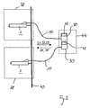
- Fig. 2 are here For example, several hand screwdriver 2 at several workstations 38 via a common compressed air line 40 connected to a compressed air supply.
- the hand screwdrivers 2 are each of their associated control device 30 are controlled and connected to it via the external control line 10.
- the control devices 30 can in this case in a common unit 44 may be integrated, as indicated by the dashed lines. How out This schematic illustration shows, are for connecting the hand screwdriver 2 at the workplace only one compressed air connection and the connection necessary to the control device 30. Further components are on respective job 38 is not required. The establishment of such a workplace 38 is therefore very flexible and inexpensive.
- the screwdriver 2 is used to screw in a screw his fferetzsatz 12 pressed on the tightening screw, so that the Start / stop valve 22 is opened and via the pneumatic motor 18 a rotary movement is transferred to the screw cap 12.
- a predetermined Torque engages the torque clutch 14 and prevents a tightening of the screw over a defined torque value.
- the torque coupling is preferably designed adjustable. After completing screwing the start / stop valve 22 closes again. about the sensor 24 is first a switch-on or start signal S1 and then a switch-off or stop signal S2 is transmitted to the control device 30 and recorded and evaluated there.
Abstract
Description
Die Erfindung betrifft eine Druckluftschraubervorrichtung mit einem druckluftbetreibbaren Handschrauber, der einen Druckluftmotor, einen Druckluftanschluss und eine Steuerleitung aufweist.The invention relates to a pneumatic wrench device with a pneumatically operated Hand screwdriver, a compressed air motor, a compressed air connection and a control line.
Aus der DE 198 46 947 A1 ist ein überwachter Druckluftschrauber zu entnehmen, bei dem ein in der Druckluftzufuhr angeordnetes externes Ventil für die Druckluftzuführung von einer Steuereinrichtung geschalten wird. Die Steuereinrichtung ist zugleich über eine Leitung mit einem im Druckluftschrauber integrierten Sensor verbunden, der die Betätigung eines Einschalthebels erfasst. Durch die Steuereinrichtung wird überwacht, ob ein ordnungsgemäßes Anschrauben erfolgt ist. Erfasst die Steuereinrichtung eine Fehlverschraubung, so wird über eine Anzeigevorrichtung ein optisches oder akustisches Signal abgegeben, um den Bediener auf die Fehlfunktion aufmerksam zu machen. Die einzelnen Komponenten Steuereinrichtung, externes Ventil, externe Anzeigevorrichtung und Druckluftschrauber sind hierbei in örtlicher Nähe am Arbeitsplatz angeordnet, damit der Bediener Zugriff auf die einzelnen Komponenten hat.From DE 198 46 947 A1 a monitored pneumatic screwdriver can be seen, in which an arranged in the compressed air supply external valve for the compressed air supply is switched by a control device. The control device is at the same time via a line with a sensor integrated in the pneumatic screwdriver connected, which detects the operation of a switch lever. By the control device it is monitored whether a proper screwing is done. Detected the control device a Fehlverschraubung, so is via a display device an optical or audible signal is emitted to the operator to draw attention to the malfunction. The individual components control device, external valve, external indicator and pneumatic screwdriver are located in close proximity to the workplace so that the operator Has access to the individual components.
Darüber hinaus besteht die Möglichkeit, bei Auftreten einer Fehlverschraubung die Druckluftzuführung automatisch durch Schließen des Ventils zu unterbrechen. Mit einem derartigen Aufbau ist zwar eine gewisse Funktionskontrolle der Verschraubungen möglich, jedoch besteht beispielsweise bei Übersehen oder Überhören des Alarmsignals die Gefahr einer Fehlfunktion. Auch ist eine vergleichsweise leichte Manipulationsmöglichkeit gegeben, so dass trotz Alarmsignals die Schraubverbindung mangelhaft bleibt. Insbesondere in komplexen Werkstücken, beispielsweise bei einem Motorblock eines Kraftfahrzeugs, können derartige mangelhafte Verschraubungen bei einer nachfolgenden Qualitätskontrolle nicht mehr erfasst werden. In addition, there is the possibility, if a misguided Automatically interrupt compressed air supply by closing the valve. With Although such a structure is a certain function control of the fittings possible, however, exists for example in overlooking or over listening to the Alarm signal the risk of malfunction. Also, a comparatively easy one Manipulation given, so that despite alarm signal the screw remains deficient. Especially in complex workpieces, for example in an engine block of a motor vehicle, such defective Glands no longer recorded in a subsequent quality control become.
Der Erfindung liegt daher die Aufgabe zugrunde, eine Druckluftschraubervorrichtung anzugeben, die eine hohe Funktionssicherheit gewährleistet.The invention is therefore based on the object, a pneumatic wrench device specify that ensures high reliability.
Die Aufgabe wird gemäß der Erfindung gelöst durch eine Druckluftschraubervorrichtung mit einem druckluftbetreibbaren Handschrauber, der einen Druckluftmotor, einen Druckluftanschluss für eine Druckluftzufuhr und eine Steuerleitung aufweist. Im Handschrauber ist zudem ein Sperrventil für die Druckluftzuführung integriert, welches von Extern über die Steuerleitung ansteuerbar ist.The object is achieved according to the invention by a pneumatic wrench device with an air-powered hand-held screwdriver that has a compressed-air motor, has a compressed air connection for a compressed air supply and a control line. In the hand screwdriver also a check valve for the compressed air supply is integrated, which can be controlled externally via the control line.
Der wesentliche Gesichtspunkt ist hierbei in dem im Gehäuse des Handschraubers integrierten und von außerhalb ansteuerbaren Sperrventils zu sehen. Gegenüber der herkömmlichen Anordnung, bei der das Sperrventil extern beispielsweise in eine Steuereinrichtung am Arbeitsplatz integriert angeordnet ist, bietet diese Ausgestaltung den entscheidenden Vorteil, dass für den Arbeitsplatz nur noch ein Druckluftanschluss und ein Anschluss für die Steuerleitung zu einer Steuereinrichtung notwendig ist. Die Absperrung der Druckluftzufuhr beispielsweise bei einer Fehlfunktion erfolgt bei dieser Anordnung unmittelbar im Handgerät, indem ein Sperrsignal an das Sperrventil übermittelt wird. Alternativ hierzu ist das Sperrventil regelmäßig gesperrt und zum Freigeben wird ein Freigabe-Signal über die Steuerleitung übermittelt. Aufgrund der Integration des Sperrventils im Handgerät kann dabei die Steuereinrichtung auch weit entfernt und nicht in unmittelbarer Nähe des Arbeitsplatzes sein. Für die Einrichtung des Arbeitsplatzes sind daher weniger Komponenten notwendig und die Gefahr einer Manipulation ist gering.The essential point is here in the case of the glove see integrated and externally controllable check valve. Across from the conventional arrangement in which the check valve externally, for example arranged in a control device integrated in the workplace, this offers Design the decisive advantage that for the workplace only one Compressed air connection and a connection for the control line to a control device necessary is. The shut-off of the compressed air supply, for example, at a Malfunction occurs in this arrangement directly in the handset by a Block signal is transmitted to the check valve. Alternatively, the check valve is regularly disabled and to release a release signal via the control line transmitted. Due to the integration of the check valve in the handset can while the control device also far away and not in the immediate vicinity of the Workplace. For the establishment of the workplace are therefore less Components necessary and the risk of manipulation is low.
Um einer Manipulation und einer Fehlbedienung vorzubeugen, ist in einer zweckdienlichen Weiterbildung vorgesehen, dass das Sperrventil derart ausgebildet ist, dass es ausschließlich über die Steuerleitung von extern wieder freigegeben werden kann. Es besteht also keine Möglichkeit, das Sperrventil vom Handschrauber aus wieder zu öffnen. Bei Auftreten einer Fehlfunktion, die zum Absperren des Sperrventils geführt hat, ist daher der Benutzer gezwungen, das Sperrventil an der Steuereinrichtung wieder freizugeben. To prevent manipulation and misuse is in a convenient Further development provided that the check valve is designed such that it is only released externally via the control line can. So there is no way the check valve from the hand screwdriver to reopen. In the event of a malfunction, which is to shut off the Therefore, the user is forced to the check valve on the Release control device again.
In einer zweckdienlichen Weiterbildung ist im Handschrauber ein weiteres Ventil vorgesehen, welches vom Handschrauber aus betätigbar ist und als Start-Stopp-Ventil ausgebildet ist. Dieses weitere Ventil ist daher für die normale Schaltfunktion vorgesehen, um den Druckluftmotor mit Druckluft zu beaufschlagen und somit die Verschraubung herbeizuführen. Prinzipiell besteht auch die Möglichkeit, auf dieses weitere Ventil zu verzichten und über das elektronisch gesteuerte Sperrventil neben der Zwangsabsperrung auch die Funktion des normalen Ein- und Ausschaltens vorzunehmen.In an expedient development is in the hand screwdriver another valve provided, which can be actuated by the manual wrench and as a start-stop valve is trained. This additional valve is therefore for the normal switching function provided to pressurize the air motor with compressed air and thus to bring about the screw connection. In principle, there is also the possibility to to dispense with this additional valve and the electronically controlled shut-off valve in addition to the forced shutdown, the function of the normal on and off Turn off.
Zweckdienlicherweise ist zur Überwachung der Einschalt- und Ausschaltvorgänge zumindest ein Sensor vorgesehen, der an die Steuerleitung angeschlossen ist. Bei einem üblichen Handschrauber wird das Start-/Stopp-Ventil durch ein Aufsetzen des Schraubers auf den Schraubenkopf mechanisch beispielsweise über einen Ventilstift geöffnet. Der Sensor ist hierbei insbesondere als Näherungsschalter ausgebildet, welcher die Position eines Verschlusselements des Ventils überwacht. Über den zumindest einen Sensor wird daher an die Steuereinrichtung ein Einschalt- und ein Abschaltsignal übermittelt. Mit Hilfe dieser Signale wird insbesondere überwacht, ob die notwendige Schraubdauer erreicht oder überschritten wird oder ob die erforderliche Anzahl von Verschraubungen pro Werkstück vorgenommen wurden.Conveniently, to monitor the turn-on and turn-off provided at least one sensor which is connected to the control line. In a conventional hand-held screwdriver, the start / stop valve is put on the screwdriver on the screw head mechanically, for example via a Valve pin opened. The sensor is in this case in particular as a proximity switch formed, which monitors the position of a closure element of the valve. The at least one sensor is therefore connected to the control device Power-on and a shutdown signal transmitted. In particular, with the help of these signals monitors whether the necessary screwing time has been reached or exceeded or whether the required number of screw connections per workpiece is made were.
Gemäß einer zweckdienlichen Weiterbildung ist weiterhin zur Überwachung des Drehmoments ein elektrischer Drehmomentsensor vorgesehen, der ebenfalls an die Steuerleitung angeschlossen und im Betrieb über diese mit der Steuereinrichtung verbunden ist. Über den Drehmomentsensor wird daher ein Drehmoment-Signal der Steuereinrichtung übermittelt, anhand dessen überprüft wird, ob das Drehmoment innerhalb des vorgeschriebenen Bereichs liegt oder ob beispielsweise durch zu frühes Abheben oder wegen einer defekten Schraube das minimal oder das maximal zulässige Drehmoment unter- bzw. überschritten wurde. According to an expedient development is still to monitor the Torque provided an electric torque sensor, which also on connected to the control line and in operation on this with the control device connected is. The torque sensor therefore becomes a torque signal the control device is transmitted, is checked by means of whether the torque is within the prescribed range or, for example due to early take-off or because of a defective screw the minimum or maximum torque was exceeded or exceeded.
Vorzugsweise ist weiterhin am Handschrauber ein vom Bediener wahrnehmbares Anzeigeelement vorgesehen, welches über die Steuerleitung ansteuerbar ist. Durch das Anzeigeelement ist insbesondere eine optische Anzeige mittels Leuchtdioden gebildet, die für unterschiedliche Betriebszustände unterschiedliche Signale abgibt. Das Anzeigelement kann auch als akustisches Signalelement ausgebildet sein. Im einfachsten Fall ist die Anzeige als in Ordnung / nicht in Ordnung-Anzeige ausgebildet.Preferably, further on the handheld wrench a perceptible by the operator Display element provided which can be controlled via the control line. The display element is in particular an optical display by means of LEDs formed, the different signals for different operating conditions emits. The display element can also be designed as an acoustic signal element be. In the simplest case, the display is OK / not OK educated.
Im Handschrauber sind die vorab genannten Komponenten, insbesondere das elektrisch ansteuerbare Sperrventil, der zumindest eine elektrische Sensor zur Ermittlung des Ein- und Ausschaltens, sowie der Drehmomentsensor integriert und an die Steuerleitung angeschlossen. Für die Verbindung der Steuerleitung zu der Steuereinrichtung ist zweckdienlicherweise am Handschrauber ein elektrischer Kontaktstecker vorgesehen. Bei dieser Ausführungsvariante braucht der Handschrauber am Arbeitsplatz daher nur noch an einem am Arbeitsplatz zur Verfügung gestellten Druckluftanschluss und einen Anschluss für die Steuerleitung angeschlossen werden und ist dann sofort betriebsbereit. Durch die elektrische Fernüberwachung und Fernsteuerung dieser drei Komponenten werden in der Steuereinrichtung vorzugsweise alle Betriebszustände und Funktionen des Handschraubers überwacht und bei Auftreten einer Fehlfunktion wird der Handschrauber gesperrt. Aus den an die Steuereinrichtung übermittelten Signalen lässt sich nämlich insbesondere die Anzahl der Verschraubungen je Werkstück, der Drehmomentverlauf pro Verschraubung sowie die Zeitdauer pro Verschraubung ermitteln und überprüfen, ob diese Werte innerhalb vorgegebener Sollbereiche liegen.In the hand screwdriver are the components mentioned above, in particular the electrically controllable shut-off valve, the at least one electrical sensor for Determination of switching on and off, as well as the torque sensor integrated and connected to the control line. For the connection of the control line to The control device is expediently an electric power tool on the handheld screwdriver Contact plug provided. In this embodiment, the hand screwdriver needs at work, therefore, only one at work available connected compressed air connection and a connection for the control line connected be ready for use immediately. Through the electrical remote monitoring and remote control of these three components are in the controller preferably all operating conditions and functions of the hand screwdriver monitored and in case of malfunction, the hand screwdriver is locked. From the signals transmitted to the control device can namely namely in particular the number of screw connections per workpiece, the torque curve per fitting and determine the length of time per fitting and check whether these values are within specified target ranges.
Um eine Manipulation zu verhindern ist das Sperrventil lediglich über die Steuereinrichtung und von einer befugten Person freigebbar. An der Steuereinrichtung ist dabei insbesondere eine Authentifizierung der Person erforderlich, die das Sperrventil wieder frei gibt.In order to prevent manipulation, the check valve is only via the control device and released by an authorized person. At the control device In particular, an authentication of the person is required that the Lock valve releases again.
Um den Anreiz einer Manipulation weiterhin herabzusenken, ist in einer zweckdienlichen Ausgestaltung weiterhin vorgesehen, dass die Steuereinrichtung vom Arbeitsplatz entfernt angeordnet ist, so dass zur Freigabe des Sperrventils der Arbeitsplatz verlassen werden muss. Der Benutzer ist daher gezwungen, den Arbeitsprozess zu unterbrechen. Insbesondere bei einer auf Akkord angelegten Produktion entfällt durch diese Maßnahme der Anreiz zu einer Manipulation. Zudem ist durch die entfernte Anordnung der Steuereinrichtung der jeweilige Arbeitsplatz mit weniger Geräten ausgestattet und damit übersichtlicher gestaltet.To further lower the incentive of manipulation is in a useful Design further provided that the control device of Workplace is arranged away, so that to release the check valve the Workplace must be left. The user is therefore forced to the work process to interrupt. Especially with a chord created Production eliminates this incentive to manipulation. moreover is by the remote arrangement of the control device of the respective workplace equipped with fewer devices and thus made clearer.
Zweckdienlicherweise ist die Steuereinrichtung hierbei in ein übergeordnetes Prozessüberwachungssystem integriert. In diesem werden unterschiedlichste Produktionsabläufe überwacht und kontrolliert, um eine möglichst weitgehende Qualitäts- und Produktionskontrolle des gesamten Produktionsprozesses zu ermöglichen. Die Integration in ein übergeordnetes Prozessüberwachungssystem erlaubt hierbei insbesondere eine weitgehend vollständige Erfassung von werkstückpezifischen Qualitäts-Daten, so dass bei Bedarf für jede einzelne Schraube anhand der erfassten Qualitäts-Kenndaten nachgewiesen werden kann, dass die Verschraubung in Ordnung war.Conveniently, the control device is in this case in a higher-level process monitoring system integrated. In this are different production processes monitored and controlled in order to ensure the highest possible quality and to enable production control of the entire production process. Integration into a higher-level process monitoring system allows this in particular, a largely complete detection of workpiece-specific Quality data, so that when needed for each screw based on the recorded quality characteristics can be demonstrated that the screwing was okay.
Ausführungsbeispiele der Erfindung werden im folgenden anhand der Zeichnung näher erläutert. Es zeigen
- Fig. 1
- eine Querschnittsdarstellung eines erfindungsgemäßen Handschraubers,
- Fig. 2
- eine Druckluftschraubervorrichtung in einer schematischen, stark vereinfachten Darstellung, bei der zwei Handschrauber an eine gemeinsame Druckluftversorgung angeschlossen sind.
- Fig. 1
- a cross-sectional view of a glove according to the invention,
- Fig. 2
- a compressed air screwdriver device in a schematic, highly simplified representation, in which two hand screwdrivers are connected to a common compressed air supply.
In den Figuren sind gleichwirkende Teile mit den gleichen Bezugszeichen versehen.
Die Schnittdarstellung gemäß Fig. 1 ist angelehnt an eine Konstruktions-
oder Werkstattzeichnung, in der die einzelnen Komponenten eines Handschraubers
2 in für den Fachmann üblicher und verständlicher Weise eingezeichnet sind.
Es werden im folgenden daher lediglich die einzelnen Funktionsblöcke des Handschraubers
2 näher erläutert. Der Aufbau der einzelnen Funktionsblöcke an sich
ist bekannt bzw. für den Fachmann ohne Weiteres auszuführen.In the figures, like-acting parts are provided with the same reference numerals.
The sectional view of FIG. 1 is based on a construction
or workshop drawing, in which the individual components of a
Der in der Fig. 1 dargestellte Druckluft-Handschrauber 2 basiert auf einem herkömmlichen
Drucklufthandschrauber mit Abschaltkupplung, in den mehrere zusätzliche
Komponenten integriert sind, welche der Funktionskontrolle bzw. der
Funktionssicherung des Betriebs des Handschraubers 2 dienen.The illustrated in Fig. 1
Der Handschrauber 2 weist ein Gehäuse 4 auf, welches an seinem rückwärtigen
Ende einen Druckluftanschluss 6 sowie einen elektrischen Anschluss 8 für eine
hier ausschnittsweise dargestellte insbesondere mehradrige externe Steuerleitung
10 aufweist. Die einzelnen Adern der externen Steuerleitung 10 sind vom elektrischen
Anschluss 8 aus über hier der Übersichtlichkeit halber nicht näher dargestellte
interne im Inneren des Gehäuses 4 verlaufende Steuerleitungen mit verschiedenen
Komponenten zu deren Kontrolle, also Überwachung bzw. Ansteuerung,
verbunden, wie nachfolgend noch näher ausgeführt wird.The
Im vorderen Bereich des Handschraubers 2 ist ein Schraubaufsatz 12 angeordnet,
über den bei Betätigung des Handschraubers 2 Schrauben in ein Werkstück eingedreht
werden. Ausgehend vom Schraubaufsatz 12, also dem vorderen Ende
des langgestreckten Handschraubers 2, sind in Richtung zum hinteren Ende eine
mechanische Drehmomentkupplung 14, ein Drehmomentsensor 16, ein Druckluftmotor
18, ein über einen Ventilstift 20 mechanisch betätigbares Start/Stopp-Ventil
22, ein Sensor 24 für das Ventil 22 sowie ein Sperrventil 26 angeordnet. Weiterhin
ist an der Außenseite am Gehäuse 4 ein optisches Anzeigeelement 28 mit
Leuchtdioden vorgesehen.In the front area of the
Insbesondere der Drehmomentsensor 16, der Sensor 24, das Sperrventil 26 sowie
das Anzeigeelement 28 sind jeweils über eine interne Steuerleitung zunächst
mit dem elektrischen Anschluss 8 und dann weitergehend über die externe Steuerleitung
10 mit einer Steuereinrichtung 30 (vgl. Fig. 2) verbunden. In particular, the
Als Drehmomentsensor 16 wird ein elektrischer Drehmomentsensor, beispielsweise
ein sogenannter DMS(Dehn-Mess-Streifen)-Drehmomentsensor eingesetzt.
Der Sensor 24 ist beispielsweise als Näherungsschalter ausgebildet und erfasst
die Position eines Verschlusselements 32 des in der Ausführungsform als Kugelventil
ausgebildeten Ventils 22. Das Verschlusselement 32 wird hierbei über den
Ventilstift 20 betätigt, der in mechanischer Wirkverbindung mit dem Schraubaufsatz
12 steht. Durch Aufsetzen des federnd gelagerten Schraubaufsatzes 12 und
Anpressen gegen die Schraube mit einem vorbestimmten Druck wird der Ventilstift
20 innerhalb des Handschraubers 2 nach hinten geschoben, so dass das
Ventil 22 öffnet.As the
Bei dem Sperrventil 26 handelt es sich insbesondere um ein herkömmliches, elektrisch
ansteuerbares Pneumatik-Ventil, welches derart ausgebildet ist, dass es
bei seiner Aktivierung zu einer Zwangsunterbrechung einer Druckluftzuführung 34
zu dem Druckluftmotor 18 führt. An der Unterseite des Gehäuses 4 ist weiterhin
ein Einstellhebel 36 vorgesehen, über den die Drehrichtung des Schraubaufsatzes
12 eingestellt werden kann.The
Ein derartiger Handschrauber 2 wird beispielsweise innerhalb einer Produktionsstraße
an einem Arbeitsplatz 38 vorgesehen. Wie in Fig. 2 dargestellt ist sind hierbei
beispielsweise mehrere Handschrauber 2 an mehreren Arbeitsplätzen 38 über
eine gemeinsame Druckluftleitung 40 an eine Druckluftversorgung angeschlossen.
Die Handschrauber 2 werden jeweils von der ihnen zugeordneten Steuereinrichtung
30 kontrolliert und sind mit dieser über die externe Steuerleitung 10 verbunden.
Die Steuereinrichtungen 30 können hierbei in einer gemeinsamen Baueinheit
44 integriert sein, wie durch die gestrichelte Linienführung angedeutet ist. Wie aus
dieser schematischen Darstellung hervorgeht, sind zum Anschluss des Handschraubers
2 am Arbeitsplatz lediglich ein Druckluftanschluss sowie der Anschluss
an die Steuereinrichtung 30 notwendig. Weitergehende Komponenten sind am
jeweiligen Arbeitsplatz 38 nicht erforderlich. Die Einrichtung eines derartigen Arbeitsplatzes
38 ist daher sehr flexibel und kostengünstig. Such a
Beim Betrieb wird zum Einschrauben einer Schraube der Handschrauber 2 mit
seinem Schraubaufsatz 12 auf die anzuziehende Schraube gedrückt, so dass das
Start-/Stopp-Ventil 22 geöffnet wird und über den Druckluftmotor 18 eine Drehbewegung
auf den Schraubaufsatz 12 übertragen wird. Bei Erreichen eines vorbestimmten
Drehmoments greift die Drehmomentkupplung 14 ein und verhindert
ein Anziehen der Schraube über einen definierten Drehmomentwert. Um diesen
festzulegen ist die Drehmomentkupplung vorzugsweise einstellbar ausgebildet.
Nach erfolgtem Einschraubvorgang schließt das Start/Stopp-Ventil 22 wieder. Über
den Sensor 24 wird zunächst ein Einschalt- oder Startsignal S1 und anschließend
ein Ausschalt- oder Stoppsignal S2 an die Steuereinrichtung 30 übermittelt
und dort erfasst und ausgewertet.During operation, the
Während des Schraubvorgangs wird weiterhin über den Drehmomentsensor 16
oder Drehmomentaufnehmer das auf die Schraube ausgeübte Drehmoment erfasst
und als Drehmomentsignal S3 an die Steuereinrichtung 30 übermittelt und
dort ausgewertet.During the screwing process continues via the
Aus den erfassten Signalen werden insbesondere die Zeitdauer einer jeweiligen
Verschraubung sowie der Drehmomentverlauf erfasst. Aus diesen beiden Kenndaten
ermittelt die Steuereinrichtung 30, ob die Verschraubung der jeweiligen
Schraube in Ordnung ist. Wird beispielsweise eine vorgegebene Zeitdauer aufgrund
eines frühzeitigen Abhebens durch den Benutzer unterschritten oder wird
das maximale Drehmoment zu früh aufgrund einer schadhaften Schraube erreicht,
so wird dies von der Steuereinrichtung 30 als Fehlverschraubung erkannt.
In diesem Fall wird von der Steuereinrichtung 30 ein Sperrsignal S4 an das Sperrventil
26 übermittelt, woraufhin dieses zwangsweise die Druckluftzuführung 34
unterbricht und ein Weiterarbeiten mit dem Handschrauber 2 unterbindet. Von der
Steuereinrichtung wird weiterhin ein Anzeigesignal S5 an das Anzeigeelement 28
übermittelt, je nachdem ob die Verschraubung in Ordnung oder nicht in Ordnung
ist. In particular, the duration of each of the detected signals
Screw connection and the torque curve detected. From these two characteristics
determines the
Das Sperrventil 26 ist hierbei derart ausgebildet, dass es ausschließlich über die
Steuereinrichtung 30 wieder von extern geöffnet werden kann, um ein Weiterarbeiten
mit dem Handschrauber zu ermöglichen. Hierzu ist an der Steuereinrichtung
30 ein Freigabeelement 42 vorgesehen. Dieses kann nur von authorisierten
Personen beispielsweise durch Verwendung eines entsprechenden
Schlüssels oder Codes betätigt werden.The
Ein entscheidender Gesichtspunkt des Handschraubers 2 ist in dem integrierten
Sperrventil 26 zu sehen, welches insbesondere elektrisch von außerhalb ansteuerbar
ist. Weitere wichtige Gesichtspunkte sind in den weiteren elektrisch ansteuerbaren
Komponenten, insbesondere dem Drehmomentensensor 16 sowie dem
Sensor 24 zu sehen, über die eine vollständige Funktionsüberwachung über die
Steuereinrichtung 30 ermöglicht wird. Die von der Steuereinrichtung 30 erfassten
Daten des Handschraubers 2 werden weiterhin zweckdienlicherweise in ein übergeordnetes
Prozessüberwachungssystem eingespeist, in das die Daten einer
Vielzahl von unterschiedlichen Werkzeugen und Maschinen einfließen. Insbesondere
bei einer Produktionsstraße, bei der ein zu bearbeitendes Werkstück eine
Vielzahl von unterschiedlichen Arbeitsvorgängen an mehreren Arbeitsplätzen
durchläuft, wird eine möglichst vollständige Qualitätskontrolle und Qualitätsicherung
jedes einzelnen Arbeitsschritts erreicht. A crucial aspect of the hand-held
- 2.Second
- HandschrauberHandschrauber
- 4.4th
- Gehäusecasing
- 6.6th
- DruckluftanschlussCompressed air connection
- 8.8th.
- elektrischer Anschlusselectrical connection
- 10.10th
- externe Steuerleitungexternal control line
- 12.12th
- SchraubaufsatzScrew Attachment
- 14.14th
- Drehmomentkupplungtorque coupling
- 16.16th
- Drehmomentsensortorque sensor
- 18.18th
- DruckluftmotorAir Motor
- 20.20th
- Ventilstiftvalve pin
- 22.22nd
- Start-/Stopp-VentilStart / stop valve
- 24.24th
- Sensorsensor
- 26.26th
- Sperrventilcheck valve
- 28.28th
- Anzeigeelementdisplay element
- 30.30th
- Steuereinrichtungcontrol device
- 32.32nd
- Verschlusselementclosure element
- 34.34th
- DruckluftzuführungCompressed air supply
- 36.36th
- Einstellhebeladjustment
- 38.38th
- ArbeitsplatzWorkplace
- 40.40th
- DruckluftleitungCompressed air line
- 42.42nd
- Freigabeelementrelease element
- 44.44th
- Baueinheitunit
- S1S1
- Startsignalstart signal
- S2S2
- Stoppsignalstop signal
- S3S3
- Drehmomentsignaltorque signal
- S4S4
- Sperrsignalblocking signal
- S5S5
- Anzeigesignaldisplay signal
Claims (11)
Applications Claiming Priority (2)
| Application Number | Priority Date | Filing Date | Title |
|---|---|---|---|
| DE200420004530 DE202004004530U1 (en) | 2004-03-23 | 2004-03-23 | Pneumatic screwdriver device |
| DE202004004530U | 2004-03-23 |
Publications (2)
| Publication Number | Publication Date |
|---|---|
| EP1579957A2 true EP1579957A2 (en) | 2005-09-28 |
| EP1579957A3 EP1579957A3 (en) | 2009-07-29 |
Family
ID=34833334
Family Applications (1)
| Application Number | Title | Priority Date | Filing Date |
|---|---|---|---|
| EP05002097A Withdrawn EP1579957A3 (en) | 2004-03-23 | 2005-02-02 | Compressed air screwdriver |
Country Status (2)
| Country | Link |
|---|---|
| EP (1) | EP1579957A3 (en) |
| DE (1) | DE202004004530U1 (en) |
Cited By (2)
| Publication number | Priority date | Publication date | Assignee | Title |
|---|---|---|---|---|
| EP2937182A1 (en) | 2014-04-23 | 2015-10-28 | Jürgen Fehlings | Device for screwing components |
| EP2937183A1 (en) | 2014-04-23 | 2015-10-28 | Jürgen Fehlings | Method for actuating a device for screwing components, and device for carrying out the method |
Families Citing this family (1)
| Publication number | Priority date | Publication date | Assignee | Title |
|---|---|---|---|---|
| DE102011103656A1 (en) | 2011-06-08 | 2012-12-13 | Daimler Ag | Compressed air screwdriver for attaching or loosening screw during assembly of motor car, has generator connected with light source, which is attached at housing such that light from source radiates towards screwing area |
Citations (4)
| Publication number | Priority date | Publication date | Assignee | Title |
|---|---|---|---|---|
| US5117919A (en) * | 1989-09-11 | 1992-06-02 | The Rotor Tool Company | Torque control system and method |
| GB2265728A (en) * | 1992-04-03 | 1993-10-06 | Stanley Works | System and method to compensate for torque overshoot in rotary power tools |
| US6311786B1 (en) * | 1998-12-03 | 2001-11-06 | Chicago Pneumatic Tool Company | Process of determining torque output and controlling power impact tools using impulse |
| US20020056557A1 (en) * | 2000-11-15 | 2002-05-16 | The Stanley Works | Pneumatic tool and system for applying torque to fasteners |
-
2004
- 2004-03-23 DE DE200420004530 patent/DE202004004530U1/en not_active Expired - Lifetime
-
2005
- 2005-02-02 EP EP05002097A patent/EP1579957A3/en not_active Withdrawn
Patent Citations (4)
| Publication number | Priority date | Publication date | Assignee | Title |
|---|---|---|---|---|
| US5117919A (en) * | 1989-09-11 | 1992-06-02 | The Rotor Tool Company | Torque control system and method |
| GB2265728A (en) * | 1992-04-03 | 1993-10-06 | Stanley Works | System and method to compensate for torque overshoot in rotary power tools |
| US6311786B1 (en) * | 1998-12-03 | 2001-11-06 | Chicago Pneumatic Tool Company | Process of determining torque output and controlling power impact tools using impulse |
| US20020056557A1 (en) * | 2000-11-15 | 2002-05-16 | The Stanley Works | Pneumatic tool and system for applying torque to fasteners |
Cited By (2)
| Publication number | Priority date | Publication date | Assignee | Title |
|---|---|---|---|---|
| EP2937182A1 (en) | 2014-04-23 | 2015-10-28 | Jürgen Fehlings | Device for screwing components |
| EP2937183A1 (en) | 2014-04-23 | 2015-10-28 | Jürgen Fehlings | Method for actuating a device for screwing components, and device for carrying out the method |
Also Published As
| Publication number | Publication date |
|---|---|
| DE202004004530U1 (en) | 2005-08-04 |
| EP1579957A3 (en) | 2009-07-29 |
Similar Documents
| Publication | Publication Date | Title |
|---|---|---|
| EP0182986B1 (en) | Powered wrench with variable torque adjustment | |
| EP2147755B1 (en) | Drilling machine, in particular core hole drilling machine, and method for controlling such | |
| DE102007000281A1 (en) | Method for controlling a screwdriver | |
| CN101124068A (en) | Hydraulic torque wrench system | |
| EP0699508A1 (en) | Hydraulic impact screwdriver especially for tightening threaded connection | |
| DE19620782A1 (en) | Screw connection prodn. method by turning screw element using electric driven screwdriver | |
| WO2017064225A1 (en) | Hand-held power tool | |
| DE102007043035A1 (en) | Motorized hand tool used as screwdriver comprises a sensor formed as a proximity switch arranged in the housing of the tool below a handle region | |
| EP1579957A2 (en) | Compressed air screwdriver | |
| DE3912991A1 (en) | Electric hand drill or screwdriver - has stop switch for automatic cut=out motor at required penetration depth | |
| EP0845631B1 (en) | Lubricant dispenser | |
| EP1788597B1 (en) | Battery-operated electric handtool | |
| EP2249994B1 (en) | Hydraulic pressure supply unit for a power screwdriver | |
| DE4243069C2 (en) | Pulse tool, especially pulse screwdriver | |
| EP2114623B1 (en) | Screwing tool | |
| EP3372343B1 (en) | Assembly consisting of a torque-discharging support arm and a screwdriver | |
| WO2008009624A1 (en) | Power screwdriver | |
| EP1030064B1 (en) | Pressure switch | |
| DE2107339C3 (en) | Connection coupling for a pressure medium-operated, hand-held machine tool for connecting the pressure medium feed line | |
| EP2195917B1 (en) | Circuit arrangement for a power tool | |
| DE102015103903B4 (en) | Power wrench with direct angle and/or torque measurement | |
| DD160273A1 (en) | HYDRAULIC WRENCH | |
| EP3477121B1 (en) | Pressure limiting unit for a pressure booster and a pressure booster for driving of hydraulics tools | |
| DE10019132B4 (en) | Ratchet ring spanner for union nuts on cables | |
| DE19741548C1 (en) | Pneumatic hand-held screwdriver |
Legal Events
| Date | Code | Title | Description |
|---|---|---|---|
| PUAI | Public reference made under article 153(3) epc to a published international application that has entered the european phase |
Free format text: ORIGINAL CODE: 0009012 |
|
| AK | Designated contracting states |
Kind code of ref document: A2 Designated state(s): AT BE BG CH CY CZ DE DK EE ES FI FR GB GR HU IE IS IT LI LT LU MC NL PL PT RO SE SI SK TR |
|
| AX | Request for extension of the european patent |
Extension state: AL BA HR LV MK YU |
|
| PUAL | Search report despatched |
Free format text: ORIGINAL CODE: 0009013 |
|
| AK | Designated contracting states |
Kind code of ref document: A3 Designated state(s): AT BE BG CH CY CZ DE DK EE ES FI FR GB GR HU IE IS IT LI LT LU MC NL PL PT RO SE SI SK TR |
|
| AX | Request for extension of the european patent |
Extension state: AL BA HR LV MK YU |
|
| STAA | Information on the status of an ep patent application or granted ep patent |
Free format text: STATUS: THE APPLICATION IS DEEMED TO BE WITHDRAWN |
|
| 18D | Application deemed to be withdrawn |
Effective date: 20090901 |