EP1579819A1 - Improved intraosteal dental implant - Google Patents
Improved intraosteal dental implant Download PDFInfo
- Publication number
- EP1579819A1 EP1579819A1 EP04007245A EP04007245A EP1579819A1 EP 1579819 A1 EP1579819 A1 EP 1579819A1 EP 04007245 A EP04007245 A EP 04007245A EP 04007245 A EP04007245 A EP 04007245A EP 1579819 A1 EP1579819 A1 EP 1579819A1
- Authority
- EP
- European Patent Office
- Prior art keywords
- dental implant
- intraosteal
- shoulder
- implant
- interface
- Prior art date
- Legal status (The legal status is an assumption and is not a legal conclusion. Google has not performed a legal analysis and makes no representation as to the accuracy of the status listed.)
- Granted
Links
Images


Classifications
-
- A—HUMAN NECESSITIES
- A61—MEDICAL OR VETERINARY SCIENCE; HYGIENE
- A61C—DENTISTRY; APPARATUS OR METHODS FOR ORAL OR DENTAL HYGIENE
- A61C8/00—Means to be fixed to the jaw-bone for consolidating natural teeth or for fixing dental prostheses thereon; Dental implants; Implanting tools
- A61C8/0048—Connecting the upper structure to the implant, e.g. bridging bars
- A61C8/005—Connecting devices for joining an upper structure with an implant member, e.g. spacers
- A61C8/0063—Connecting devices for joining an upper structure with an implant member, e.g. spacers with an internal sleeve
-
- A—HUMAN NECESSITIES
- A61—MEDICAL OR VETERINARY SCIENCE; HYGIENE
- A61C—DENTISTRY; APPARATUS OR METHODS FOR ORAL OR DENTAL HYGIENE
- A61C8/00—Means to be fixed to the jaw-bone for consolidating natural teeth or for fixing dental prostheses thereon; Dental implants; Implanting tools
- A61C8/0048—Connecting the upper structure to the implant, e.g. bridging bars
- A61C8/005—Connecting devices for joining an upper structure with an implant member, e.g. spacers
-
- A—HUMAN NECESSITIES
- A61—MEDICAL OR VETERINARY SCIENCE; HYGIENE
- A61C—DENTISTRY; APPARATUS OR METHODS FOR ORAL OR DENTAL HYGIENE
- A61C8/00—Means to be fixed to the jaw-bone for consolidating natural teeth or for fixing dental prostheses thereon; Dental implants; Implanting tools
- A61C8/0048—Connecting the upper structure to the implant, e.g. bridging bars
- A61C8/005—Connecting devices for joining an upper structure with an implant member, e.g. spacers
- A61C8/0069—Connecting devices for joining an upper structure with an implant member, e.g. spacers tapered or conical connection
-
- A—HUMAN NECESSITIES
- A61—MEDICAL OR VETERINARY SCIENCE; HYGIENE
- A61C—DENTISTRY; APPARATUS OR METHODS FOR ORAL OR DENTAL HYGIENE
- A61C8/00—Means to be fixed to the jaw-bone for consolidating natural teeth or for fixing dental prostheses thereon; Dental implants; Implanting tools
- A61C8/0018—Means to be fixed to the jaw-bone for consolidating natural teeth or for fixing dental prostheses thereon; Dental implants; Implanting tools characterised by the shape
- A61C8/0022—Self-screwing
-
- A—HUMAN NECESSITIES
- A61—MEDICAL OR VETERINARY SCIENCE; HYGIENE
- A61C—DENTISTRY; APPARATUS OR METHODS FOR ORAL OR DENTAL HYGIENE
- A61C8/00—Means to be fixed to the jaw-bone for consolidating natural teeth or for fixing dental prostheses thereon; Dental implants; Implanting tools
- A61C8/0048—Connecting the upper structure to the implant, e.g. bridging bars
- A61C8/005—Connecting devices for joining an upper structure with an implant member, e.g. spacers
- A61C8/0054—Connecting devices for joining an upper structure with an implant member, e.g. spacers having a cylindrical implant connecting part
-
- A—HUMAN NECESSITIES
- A61—MEDICAL OR VETERINARY SCIENCE; HYGIENE
- A61C—DENTISTRY; APPARATUS OR METHODS FOR ORAL OR DENTAL HYGIENE
- A61C8/00—Means to be fixed to the jaw-bone for consolidating natural teeth or for fixing dental prostheses thereon; Dental implants; Implanting tools
- A61C8/0048—Connecting the upper structure to the implant, e.g. bridging bars
- A61C8/005—Connecting devices for joining an upper structure with an implant member, e.g. spacers
- A61C8/0056—Connecting devices for joining an upper structure with an implant member, e.g. spacers diverging in the apical direction of the implant or abutment
-
- A—HUMAN NECESSITIES
- A61—MEDICAL OR VETERINARY SCIENCE; HYGIENE
- A61C—DENTISTRY; APPARATUS OR METHODS FOR ORAL OR DENTAL HYGIENE
- A61C8/00—Means to be fixed to the jaw-bone for consolidating natural teeth or for fixing dental prostheses thereon; Dental implants; Implanting tools
- A61C8/0048—Connecting the upper structure to the implant, e.g. bridging bars
- A61C8/0077—Connecting the upper structure to the implant, e.g. bridging bars with shape following the gingival surface or the bone surface
Definitions
- the present invention relates in general to an improved intraosteal dental implant and in particular to an intraosteal dental implant with an improved geometry of the soft tissue apposition surface.
- Intraosteal implants are widely used in dental restorations to support fixed or removable prostheses where the natural root of a teeth has been lost.
- Schroeder et al. Oral Implantology, Georg Thieme Verlag Stuttgart and New York, 2 nd edition, 1996, p. 128, relates to an implant to be inserted transgingivally into a jaw bone having an apically extending shank portion, on which there may be an external thread, and which terminates at the very bottom with an implant tip.
- the shank portion is adjoined by an implant neck which terminates at the very top with an implant shoulder which conically tapers coronally.
- an additive and/or non-additive surface structuring is provided on the implant, the surface extending over the shank portion to a horizontal structure boundary situated on the implant neck.
- the boundary defines an interface between a bone tissue apposition surface of the implant and a soft-tissue apposition surface of the implant.
- WO-A-01 49199 which was assigned to the assignee of the present invention and the content of which is herewith fully incorporated by reference, has proposed an intraosteal dental implant with an anatomically suitable conformation for aesthetic restoration, in particular, in the front teeth region.
- the known implant comprises an additive or a non-additive surface structure, in order to favor osteal integration, the surface structure extending over the shank section up to a structure boundary or interface on the neck of the implant.
- the structure boundary falls anteriorly in the apical direction to a low point and rises, on the proximal implant edge, to a high point.
- the shoulder of the implant is anatomically formed to follow the boundary or interface such that, on the interdental side surfaces, raised regions exist and, on each of the anterior and posterior implant edges, recessed regions exist.
- an object of the invention to provide for an improved intraosteal dental implant which avoids the drawbacks of the prior art and which is readily accessible to the implantologist in particular in the palatal or lingual area, while still conforming with aesthetic requirements.
- Another object of the present invention is to provide an abutment suitable for the dental implant of the present invention.
- an intraosteal dental implant generally designated with reference numeral 1 with an apical tip 1'.
- the dental implant 1 has a bone tissue apposition surface 2 which is typically threaded and/or roughened in a known manner and extends into the alveolar bone in the inserted state of the dental implant.
- the shown dental implant has a screw like appearance, it will be appreciated by the person skilled in the art that other shapes like a root-like shape can be used without departing from the scope and spirit of the invention.
- the coronal end of the bone apposition surface 2 defines a lower neck portion surface 2a.
- the dental implant 1 is provided with a soft tissue apposition surface 3 extending from an upper end of the bone tissue apposition surface 2, at the neck portion surface 2a, up to a shoulder 5 of the dental implant 1.
- an interface 4 is defined between the bone tissue and soft tissue apposition surfaces.
- the soft tissue apposition surface 3 defines an upper neck portion of the dental implant 1.
- the upper neck portion surface 3 and the lower neck portion surface 2a define the neck of the dental implant 1.
- the bone tissue apposition surface 2 may be provided with an additive or non-additive surface structure extending up to the interface 4 in order to enhance the osteal integration.
- Such structure surface is well known to the person skilled in the art of dental implantology and will not be further described (see for instance Ralf-J Kohal et al., "Wurzelanaloge Titaniumimplantate (Bio-Design-Implantate” für die Sofortimplantation - Das Re-Implant®-System", Implantologie 1996; 2: 99-115).
- the soft tissue apposition surface or upper neck portion surface 3 is machined, for instance by polishing, to obtain a surface enhancing the regeneration and the attachment of the soft tissue.
- the machining of the soft tissue apposition surface is known in the art (see for instance Ralf-J Kohal et al., "Wurzelanaloge Titaniumimplantate (Bio-Design-Implantate” für die Sofortimplantation - Das Re-Implant®-System", Implantologie 1996; 2: 99-115), and therefore the discussion thereof will be omitted in the present specification.
- the provision of additives for the soft tissue apposition surface which is per se known in the art, is envisaged by the present invention.
- other machining techniques in addition to polishing, are envisaged and applicable to the present soft tissue apposition surface.
- the plane of the shoulder 5 is inclined with respect to the axis 7 of the implant 1.
- the plane of the shoulder 5 may have a slightly curved shape. This is in particular the case if the dental implant 1 is devised with an inner neck surface 18 as shown and explained in conjunction with Fig. 5A.
- the inclination reflects the morphologic difference between the palatal or lingual sides on one hand and the labial side on the other hand with respect to the alveolar bone anatomy.
- the palatal side 8b of the dental implant 1 has a larger extension than the labial side 8c thereof.
- Similar considerations apply for a lower jaw bone implant where the lingual side of the dental implant has a larger extension than that of the labial side thereof.
- the inclined shoulder 5 of the present invention assures a neck palatal side 8b or a neck lingual side (not shown) which is higher than the neck labial side 8c.
- the present invention shows particular advantages if the inclination of the plane of the shoulder 5 is in the range from about 10° to about 30° with respect to the plane perpendicular to the axis 7 of the implant 1, as indicated with ⁇ in Fig. 1A.
- the inclination with respect to the axis 7 is in the range from about 60° to about 80°.
- the more preferred inclination with respect to the axis 7 is in the range from about 65° to about 75°.
- the most preferred inclination of the plane of the shoulder 5 is of about 20° with respect to the plane perpendicular to the axis 7 of the implant 1 or about 70° with respect to the axis 7.
- Figs. 1A through 1C show the implant according to the present invention wherein the interface 4 between the lower neck portion surface 2a and the soft tissue apposition surface 3 lays in a plane and extends substantially in a parallel manner to the shoulder 5 of the dental implant 1 which also lays in a plane.
- the plane passing through the interface 4 is parallel to the plane passing through the shoulder 5.
- the lower neck portion surface 2a has a palatal side 2b which has a larger extension than a labial side 2c thereof. Same applies for the ratio between the lingual side of the lower neck portion and the labial side thereof. It is believed that the first embodiment of the dental implant according to the present invention is particularly suitable for adjacent dental implants.
- the extension (width) of the soft tissue apposition surface 3 as defined by parallel interface 4 and shoulder 5 is in the range of about 0.5 to about 3 mm, and more preferred of about 1.8 mm.
- Fig. 1B is an interdental view of an intraosteal dental implant 1 according to the present invention in the implanted state thereof.
- the dental implant 1 is located in the alveolar bone 10 which is schematically shown for explanatory purposes.
- the alveolar bone 10 is in contact with the soft tissue 11.
- an abutment 6 can be apposed on the shoulder 5 of the dental implant 1.
- the abutment 6 is built to perfectly fit on the upper surface of shoulder 5 and to take into account the inclined shoulder 5 of the dental implant 1.
- Fig. 1C further shows a section view of the dental implant 1 of the present invention.
- the section view shows a screw 9 located in a receiving bore 14 of the dental implant 1 which firmly fixes the abutment 6 to the dental implant 1.
- the abutment 6 may be advantageously provided in accordance with the present invention with a downwardly extending protrusion fitting into a respective receiving bore of the implant 1 such as to rotationally secure the latter element to another.
- the dental implant according to the first embodiment of the present invention provides for particular advantages if implemented as a two stage implant.
- the interface 4 between the apposition surface 2a and the soft tissue apposition surface 3 has a curved profile similar to the interface (boundary) shown in WO-A-01 49 199.
- the curved profile of the interface 4 is such that it is increasing from the labial side towards the interdental side and decreasing towards the palatal/lingual side.
- the curved profile is designed to better reflect the bone-soft tissue profile around the cavity wherein the implant intended to be located.
- the extension (width) of the soft tissue apposition surface 3 as defined by the curved interface 4 is in the range of about 0.5 to about 3 mm, and more preferred of about 1.8 mm, at the labial side 3c, and in the range of about 0.5 to about 3 mm, and more preferred of about 2.8 mm, at the lingual/palatal side 3b.
- the inventors of the present invention surprisingly found that for predictable bone and soft tissue preservation the plane passing through the interface 4 must not be parallel to the plane passing through the shoulder 5.
- the second embodiment of the present invention is believed to provide for a good bone tissue preservation notwithstanding the fact that the sloping of the interface 4 does not necessarily follow the outline of the bone tissue.
- the interface 4 between the bone apposition surface 2 and the soft tissue apposition surface 3 lays in a plane substantially perpendicular to the axis 7 of the implant 1.
- the extension (width) of the soft tissue apposition surface 3 as defined by the interface 4 perpendicular to the axis 7 of the dental implant 1 is in the range of about 0.5 to about 3 mm, and more preferred of about 2.3 mm at the palatal/lingual side 3b.
- Figs. 3A through 3C is the same as that of Figs. 1A through 1C and therefore the same explanations as set forth in respect to the latter apply.
- the inventors surprisingly found that for predictable bone and soft tissue preservation the plane passing through the interface 4 must not be parallel to the plane passing through the shoulder 5.
- the third embodiment of the present invention is also believed to provide for a good bone tissue preservation notwithstanding the fact that the sloping of the interface 4 does not necessarily follow the outline of the bone tissue.
- the palatal/lingual side 4b of the interface 4 between the bone tissue apposition surface 2 and the soft tissue apposition surface 3 lays in a plane which is substantially perpendicular to the axis 7 of the implant 1 and the labial side 4c of the interface 4 is curved.
- the palatal/lingual side 4b of the interface 4 resembles to the corresponding side of the third embodiment while the the curved labial side 4c of the interface 4 resembles to the corresponding side of the second embodiment.
- the fourth embodiment of the present invention is believed to provide for a good bone tissue preservation notwithstanding the fact that the sloping of the interface 4 does not necessarily follow the outline of the bone tissue.
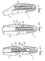
- Figs. 5A through 7 there is shown a preferred arrangement according to the present invention for the rotational positioning of the abutment 6 into the dental implant 1.
- the person skilled in the art will appreciate that the latter arrangement can be used in conjunction with all of the dental implants described above and also with further conventional prior art dental implants.
- the dental implant 1 is provided in a conventional manner with a receiving bore 14 in the form of a blind hole having an internal thread 13 and which extends axially from coronal to apical.
- a substantially circular rest surface 16 which extends in a perpendicular manner to the axis 7 of the implant and which receives substantially cylindrical sleeve 15.
- the sleeve 15 and the internal wall 17 of the bore 14 are sized such that the sleeve 15 precisely fits the internal wall 17.
- the sleeve 15 is fixedly retained in the space defined by the internal wall 17 and the rest surface 16.
- the inner neck surface 18 of the dental implant 1 defined below the shoulder 5 can have preferably a substantially conical shape with an imaginary tip 19 offset from the axis 7 of the dental implant 1.
- a complementary shaped abutment 6, as shown in Figs. 6A through 7, can be accommodated between the sleeve 15 and the inner neck surface 18 such that the abutment 6 is rotationally secured to the dental implant 1.
- the rotational securing can be achieved, for instance, by providing the intersection curve 20 between the inner neck surface 18 of the dental implant 1 and the sleeve 15 such that the intersection curve does not lay in a plane perpendicular to the axis 7 of the dental implant 1.
- Figs. 6A and 6B show a straight abutment 6 having a downwardly extending protrusion 21 with a lower surface 22 exactly matching the inner neck surface 18 of the dental implant 1.
- the downwardly extending protrusion 21 surrounds the sleeve 15 and the lower surface 22 rests on the inner neck surface 18.
- the screw 9 also fits the sleeve 15 with no or very little play to improve the stability of the arrangement.
- the thread pitch of the screw is preferably from 0,5 to 1,3 mm and more preferred from 0,5 to 0.8 mm in order to improve the positioning of the abutment.
- Fig. 7 shows an arrangement similar to that of Figs. 6A and 6B, wherein the abutment is inclined.
Landscapes
- Health & Medical Sciences (AREA)
- Oral & Maxillofacial Surgery (AREA)
- Orthopedic Medicine & Surgery (AREA)
- Dentistry (AREA)
- Epidemiology (AREA)
- Life Sciences & Earth Sciences (AREA)
- Animal Behavior & Ethology (AREA)
- General Health & Medical Sciences (AREA)
- Public Health (AREA)
- Veterinary Medicine (AREA)
- Dental Prosthetics (AREA)
- Dental Preparations (AREA)
- Materials For Medical Uses (AREA)
Abstract
Description
Claims (19)
- An intraosteal dental implant (1) having a bone tissue apposition surface (2) extending from a tip (1') of the dental implant (1) up to an interface (4) at a neck portion of the dental implant (1), and a soft tissue apposition surface (3) extending from the interface (4) to a shoulder (5) of the dental implant (1), wherein the shoulder (5) is inclined with respect to the axis (7) of the dental implant (1).
- The intraosteal dental implant (1) of claim 1, wherein the shoulder (5) is substantially contained in a plane.
- The intraosteal dental implant (1) of claims 1 or 2, wherein the shoulder (5) has an inclination in the range from about 60° to about 80°.
- The intraosteal dental implant (1) of claims 1 or 2, wherein the shoulder (5) has an inclination in the range from about 65° to about 75°.
- The intraosteal dental implant (1) of claims 1 or 2, wherein the shoulder (5) has an inclination of about 70°.
- The intraosteal dental implant (1) of one or more of claims 1-5, wherein the neck portion of the dental implant (1) has a palatal or lingual side (8b) and a labial side (8c), and wherein the palatal or lingual side (8b) has a larger extension than the labial side (8c).
- The intraosteal dental implant (1) of one or more of claims 1-6, wherein the interface (4) is substantially parallel to the shoulder (5).
- The intraosteal dental implant (1) of one or more of claims 1-6, wherein the interface (4) is substantially not parallel to the shoulder (5).
- The intraosteal dental implant (1) of one or more of claims 1-6 and 8, wherein the interface (4) has a curved profile which is increasing from the labial side towards the interdental side and decreasing towards the palatal/lingual side.
- The intraosteal dental implant (1) of one or more of claims 1-6 and 8, wherein the interface (4) is substantially perpendicular to the axis (7).
- The intraosteal dental implant (1) of one or more of claims 1-6 and 8, wherein the interface (4) has a curved profile which is increasing from the labial side towards the interdental side and a horizontal profile, substantially perpendicular to the axis (7) from the interdental side towards the palatal/lingual side.
- The intraosteal dental implant (1) of one or more of claims 1-11, further including a bore (14) in the form a blind hole, the bore (14) being shaped and devised such as to rotationally secure an abutment (6) receivable in the dental implant (1).
- The intraosteal dental implant (1) of claim 12, wherein the bore (14) is provided with a substantially cylindrical sleeve (15) extending coaxially to the dental implant (1), wherein the dental implant (1) includes an inner neck surface (18), and wherein an intersection curve (20) between the inner neck surface (18) of the dental implant (1) and the sleeve (15) does not lay in a plane perpendicular to the axis (7) of the dental implant (1).
- The intraosteal dental implant (1) of claim 12, wherein the bore (14) is provided with a substantially cylindrical sleeve (15) extending coaxially to the dental implant (1), and wherein the dental implant (1) includes an inner neck surface (18), the inner neck surface (18) of the dental implant (1) having a substantially conical shape with an imaginary tip (19) offset from the axis (7) of the dental implant (1).
- The intraosteal dental implant (1) of claims 13 or 14 in combination with an abutment (6), the abutment (6) having a downwardly extending protrusion (21) with a lower surface (22) exactly matching the inner neck surface (18) of the dental implant (1).
- The combination of claim 15, wherein in the assembled state of the abutment (6), the downwardly extending protrusion (21) surrounds the sleeve (15) and the lower surface (22) rests on the inner neck surface (18).
- The combination of claim 16, further including a screw (9) which fits into the sleeve (15) with no or very little play.
- The invention according to one or more of claims 1-17, wherein the dental implant (1) is a two stage implant.
- The invention according to one or more of claims 1-17, wherein the dental implant (1) is an one stage implant.
Priority Applications (5)
| Application Number | Priority Date | Filing Date | Title |
|---|---|---|---|
| AT04007245T ATE380517T1 (en) | 2004-03-25 | 2004-03-25 | IMPROVED ENOSSAL DENTAL IMPLANT |
| DE602004010613T DE602004010613T3 (en) | 2004-03-25 | 2004-03-25 | Improved endosseous dental implant |
| EP04007245.6A EP1579819B2 (en) | 2004-03-25 | 2004-03-25 | Improved intraosteal dental implant |
| JP2005082112A JP4689311B2 (en) | 2004-03-25 | 2005-03-22 | Improved intraosseous dental implant |
| US11/087,275 US7329124B2 (en) | 2004-03-25 | 2005-03-23 | Intraosteal dental implant |
Applications Claiming Priority (1)
| Application Number | Priority Date | Filing Date | Title |
|---|---|---|---|
| EP04007245.6A EP1579819B2 (en) | 2004-03-25 | 2004-03-25 | Improved intraosteal dental implant |
Publications (3)
| Publication Number | Publication Date |
|---|---|
| EP1579819A1 true EP1579819A1 (en) | 2005-09-28 |
| EP1579819B1 EP1579819B1 (en) | 2007-12-12 |
| EP1579819B2 EP1579819B2 (en) | 2013-06-26 |
Family
ID=34854618
Family Applications (1)
| Application Number | Title | Priority Date | Filing Date |
|---|---|---|---|
| EP04007245.6A Expired - Lifetime EP1579819B2 (en) | 2004-03-25 | 2004-03-25 | Improved intraosteal dental implant |
Country Status (5)
| Country | Link |
|---|---|
| US (1) | US7329124B2 (en) |
| EP (1) | EP1579819B2 (en) |
| JP (1) | JP4689311B2 (en) |
| AT (1) | ATE380517T1 (en) |
| DE (1) | DE602004010613T3 (en) |
Families Citing this family (13)
| Publication number | Priority date | Publication date | Assignee | Title |
|---|---|---|---|---|
| SE526746C2 (en) * | 2003-12-11 | 2005-11-01 | Nobel Biocare Ab | Implant applicable to dentures with associated soft tissue |
| ATE368426T1 (en) * | 2004-03-25 | 2007-08-15 | Straumann Holding Ag | DENTAL IMPLANT WITH POSITIONING MEANS |
| ZA200704758B (en) * | 2005-11-03 | 2008-08-27 | Southern Implants Pty Ltd | Molar implant and method |
| WO2008125097A1 (en) * | 2007-04-17 | 2008-10-23 | Dental Service Center Michael Menzel Gmbh | Dental implant system |
| US20090298014A1 (en) * | 2008-05-28 | 2009-12-03 | Global Implant Solutions, Llc | Dental Implant |
| US20100015571A1 (en) * | 2008-07-15 | 2010-01-21 | Global Implant Solutions, Llc | Flexible Abutment For Use With A Dental Implant |
| US20100119993A1 (en) * | 2008-11-11 | 2010-05-13 | Cagenix, Inc. | Dental implant |
| US8616881B2 (en) * | 2009-06-30 | 2013-12-31 | Dental Design Consultants, Llc | Modified asymmetrical dental implant |
| US8992222B2 (en) | 2012-05-02 | 2015-03-31 | Richard D. Cottrell | Ridge lap dental implant |
| US9861455B2 (en) | 2013-07-30 | 2018-01-09 | TI Intellectual Property Inc. | Dental implant system |
| WO2016118661A1 (en) * | 2015-01-22 | 2016-07-28 | Simmons Earl Wayne Jr | Methods and apparatus for implants and reconstruction |
| DE102016014348B4 (en) * | 2016-10-07 | 2019-05-16 | Metin Gürlük | implant system |
| EP4125706B8 (en) * | 2020-04-02 | 2025-09-17 | Wassef, Michael | Endosteal horizontally placed dental implant system and method |
Citations (4)
| Publication number | Priority date | Publication date | Assignee | Title |
|---|---|---|---|---|
| EP0599794A2 (en) * | 1992-11-26 | 1994-06-01 | Medevelop Ab | Anchoring element for anchorage in bone tissue |
| EP0879580A2 (en) * | 1997-05-15 | 1998-11-25 | Core-Vent Corporation | Non-submergible, one part, root form endosseous dental implants |
| WO2001050972A2 (en) * | 2000-01-11 | 2001-07-19 | Nicholas Elian | Dental implants and dental implant/prosthetic tooth systems |
| US20030104337A1 (en) * | 2001-12-03 | 2003-06-05 | Cottrell Richard Day | Modified dental implant fixture |
Family Cites Families (8)
| Publication number | Priority date | Publication date | Assignee | Title |
|---|---|---|---|---|
| US5759034A (en) † | 1996-11-29 | 1998-06-02 | Daftary; Fereidoun | Anatomical restoration dental implant system for posterior and anterior teeth |
| DE69734248T2 (en) * | 1997-02-25 | 2006-06-29 | Nobel Biocare Ab | BONE ANCHORING ELEMENT |
| WO1998052488A1 (en) * | 1997-05-24 | 1998-11-26 | Friadent Gmbh | Dental implant and device with a dental implant |
| SE510956C2 (en) * | 1997-11-11 | 1999-07-12 | Nobel Biocare Ab | Device for anchoring a threaded implant to bone, eg tooth bone, by means of a twisting tool |
| US6174167B1 (en) * | 1998-12-01 | 2001-01-16 | Woehrle Peter S. | Bioroot endosseous implant |
| DE50114754D1 (en) * | 2000-01-04 | 2009-04-23 | Straumann Holding Ag | ENOSSAL DENTAL IMPLANT |
| US6527554B2 (en) † | 2001-06-04 | 2003-03-04 | Nobel Biocare Ab | Natural implant system |
| DE60327164D1 (en) * | 2002-01-11 | 2009-05-28 | Nobel Biocare Ab | DENTAL IMPLANT SYSTEM |
-
2004
- 2004-03-25 EP EP04007245.6A patent/EP1579819B2/en not_active Expired - Lifetime
- 2004-03-25 DE DE602004010613T patent/DE602004010613T3/en not_active Expired - Lifetime
- 2004-03-25 AT AT04007245T patent/ATE380517T1/en not_active IP Right Cessation
-
2005
- 2005-03-22 JP JP2005082112A patent/JP4689311B2/en not_active Expired - Fee Related
- 2005-03-23 US US11/087,275 patent/US7329124B2/en not_active Expired - Lifetime
Patent Citations (4)
| Publication number | Priority date | Publication date | Assignee | Title |
|---|---|---|---|---|
| EP0599794A2 (en) * | 1992-11-26 | 1994-06-01 | Medevelop Ab | Anchoring element for anchorage in bone tissue |
| EP0879580A2 (en) * | 1997-05-15 | 1998-11-25 | Core-Vent Corporation | Non-submergible, one part, root form endosseous dental implants |
| WO2001050972A2 (en) * | 2000-01-11 | 2001-07-19 | Nicholas Elian | Dental implants and dental implant/prosthetic tooth systems |
| US20030104337A1 (en) * | 2001-12-03 | 2003-06-05 | Cottrell Richard Day | Modified dental implant fixture |
Also Published As
| Publication number | Publication date |
|---|---|
| EP1579819B1 (en) | 2007-12-12 |
| US20050233282A1 (en) | 2005-10-20 |
| US7329124B2 (en) | 2008-02-12 |
| JP2005270660A (en) | 2005-10-06 |
| DE602004010613T2 (en) | 2008-12-04 |
| EP1579819B2 (en) | 2013-06-26 |
| DE602004010613D1 (en) | 2008-01-24 |
| JP4689311B2 (en) | 2011-05-25 |
| ATE380517T1 (en) | 2007-12-15 |
| DE602004010613T3 (en) | 2013-12-24 |
Similar Documents
| Publication | Publication Date | Title |
|---|---|---|
| US11147654B2 (en) | Condensing skeletal implant that facilitate insertions | |
| EP1460960B1 (en) | Modified dental implant fixture | |
| US7341453B2 (en) | Dental implant method and apparatus | |
| EP2308413A2 (en) | Modified dental implant fixture | |
| KR20100022050A (en) | Ceramic one-piece dental implant | |
| KR20060135786A (en) | Anchoring elements for use with bones | |
| US20030087217A1 (en) | Dental implant method & apparatus | |
| US20030068599A1 (en) | Esthetic profile endosseous root-formed dental implant | |
| US20060084035A1 (en) | Dental implant | |
| EP1579819B1 (en) | Improved intraosteal dental implant | |
| KR20110033853A (en) | Improved Fixture for Detachable Dental Implants | |
| KR101155702B1 (en) | One body implant | |
| KR200392276Y1 (en) | Dental Implant | |
| EP1579818B1 (en) | Dental implant with positioning means | |
| EP1663050B1 (en) | Aesthetic endosteal implant | |
| KR200388933Y1 (en) | Dental Implant | |
| AU2011203341B2 (en) | Condensing Skeletal Implant that Facilitate Insertions | |
| KR200392241Y1 (en) | Dental Temporary Implant | |
| US20110244428A1 (en) | Apparatus, method and system for dental implants | |
| KR20240018759A (en) | Angle abutment for one body implant | |
| JP2005034385A (en) | Implant body | |
| KR20100005973U (en) | Angled Implant Abutment |
Legal Events
| Date | Code | Title | Description |
|---|---|---|---|
| PUAI | Public reference made under article 153(3) epc to a published international application that has entered the european phase |
Free format text: ORIGINAL CODE: 0009012 |
|
| AK | Designated contracting states |
Kind code of ref document: A1 Designated state(s): AT BE BG CH CY CZ DE DK EE ES FI FR GB GR HU IE IT LI LU MC NL PL PT RO SE SI SK TR |
|
| AX | Request for extension of the european patent |
Extension state: AL LT LV MK |
|
| 17P | Request for examination filed |
Effective date: 20060223 |
|
| AKX | Designation fees paid |
Designated state(s): AT BE BG CH CY CZ DE DK EE ES FI FR GB GR HU IE IT LI LU MC NL PL PT RO SE SI SK TR |
|
| 17Q | First examination report despatched |
Effective date: 20060607 |
|
| GRAP | Despatch of communication of intention to grant a patent |
Free format text: ORIGINAL CODE: EPIDOSNIGR1 |
|
| GRAS | Grant fee paid |
Free format text: ORIGINAL CODE: EPIDOSNIGR3 |
|
| GRAA | (expected) grant |
Free format text: ORIGINAL CODE: 0009210 |
|
| AK | Designated contracting states |
Kind code of ref document: B1 Designated state(s): AT BE BG CH CY CZ DE DK EE ES FI FR GB GR HU IE IT LI LU MC NL PL PT RO SE SI SK TR |
|
| REG | Reference to a national code |
Ref country code: GB Ref legal event code: FG4D |
|
| REG | Reference to a national code |
Ref country code: CH Ref legal event code: EP |
|
| REG | Reference to a national code |
Ref country code: IE Ref legal event code: FG4D |
|
| REF | Corresponds to: |
Ref document number: 602004010613 Country of ref document: DE Date of ref document: 20080124 Kind code of ref document: P |
|
| REG | Reference to a national code |
Ref country code: CH Ref legal event code: NV Representative=s name: MARK-PAT MODIANO S.A. |
|
| PG25 | Lapsed in a contracting state [announced via postgrant information from national office to epo] |
Ref country code: SE Free format text: LAPSE BECAUSE OF FAILURE TO SUBMIT A TRANSLATION OF THE DESCRIPTION OR TO PAY THE FEE WITHIN THE PRESCRIBED TIME-LIMIT Effective date: 20080312 |
|
| PG25 | Lapsed in a contracting state [announced via postgrant information from national office to epo] |
Ref country code: PL Free format text: LAPSE BECAUSE OF FAILURE TO SUBMIT A TRANSLATION OF THE DESCRIPTION OR TO PAY THE FEE WITHIN THE PRESCRIBED TIME-LIMIT Effective date: 20071212 Ref country code: NL Free format text: LAPSE BECAUSE OF FAILURE TO SUBMIT A TRANSLATION OF THE DESCRIPTION OR TO PAY THE FEE WITHIN THE PRESCRIBED TIME-LIMIT Effective date: 20071212 Ref country code: SI Free format text: LAPSE BECAUSE OF FAILURE TO SUBMIT A TRANSLATION OF THE DESCRIPTION OR TO PAY THE FEE WITHIN THE PRESCRIBED TIME-LIMIT Effective date: 20071212 Ref country code: FI Free format text: LAPSE BECAUSE OF FAILURE TO SUBMIT A TRANSLATION OF THE DESCRIPTION OR TO PAY THE FEE WITHIN THE PRESCRIBED TIME-LIMIT Effective date: 20071212 |
|
| NLV1 | Nl: lapsed or annulled due to failure to fulfill the requirements of art. 29p and 29m of the patents act | ||
| PG25 | Lapsed in a contracting state [announced via postgrant information from national office to epo] |
Ref country code: AT Free format text: LAPSE BECAUSE OF FAILURE TO SUBMIT A TRANSLATION OF THE DESCRIPTION OR TO PAY THE FEE WITHIN THE PRESCRIBED TIME-LIMIT Effective date: 20071212 |
|
| PG25 | Lapsed in a contracting state [announced via postgrant information from national office to epo] |
Ref country code: CZ Free format text: LAPSE BECAUSE OF FAILURE TO SUBMIT A TRANSLATION OF THE DESCRIPTION OR TO PAY THE FEE WITHIN THE PRESCRIBED TIME-LIMIT Effective date: 20071212 Ref country code: ES Free format text: LAPSE BECAUSE OF FAILURE TO SUBMIT A TRANSLATION OF THE DESCRIPTION OR TO PAY THE FEE WITHIN THE PRESCRIBED TIME-LIMIT Effective date: 20080323 |
|
| ET | Fr: translation filed | ||
| PG25 | Lapsed in a contracting state [announced via postgrant information from national office to epo] |
Ref country code: SK Free format text: LAPSE BECAUSE OF FAILURE TO SUBMIT A TRANSLATION OF THE DESCRIPTION OR TO PAY THE FEE WITHIN THE PRESCRIBED TIME-LIMIT Effective date: 20071212 Ref country code: BE Free format text: LAPSE BECAUSE OF FAILURE TO SUBMIT A TRANSLATION OF THE DESCRIPTION OR TO PAY THE FEE WITHIN THE PRESCRIBED TIME-LIMIT Effective date: 20071212 Ref country code: RO Free format text: LAPSE BECAUSE OF FAILURE TO SUBMIT A TRANSLATION OF THE DESCRIPTION OR TO PAY THE FEE WITHIN THE PRESCRIBED TIME-LIMIT Effective date: 20071212 |
|
| PLBI | Opposition filed |
Free format text: ORIGINAL CODE: 0009260 |
|
| PG25 | Lapsed in a contracting state [announced via postgrant information from national office to epo] |
Ref country code: PT Free format text: LAPSE BECAUSE OF FAILURE TO SUBMIT A TRANSLATION OF THE DESCRIPTION OR TO PAY THE FEE WITHIN THE PRESCRIBED TIME-LIMIT Effective date: 20080512 |
|
| PLAX | Notice of opposition and request to file observation + time limit sent |
Free format text: ORIGINAL CODE: EPIDOSNOBS2 |
|
| 26 | Opposition filed |
Opponent name: ASTRA TECH AB Effective date: 20080904 |
|
| PG25 | Lapsed in a contracting state [announced via postgrant information from national office to epo] |
Ref country code: DK Free format text: LAPSE BECAUSE OF FAILURE TO SUBMIT A TRANSLATION OF THE DESCRIPTION OR TO PAY THE FEE WITHIN THE PRESCRIBED TIME-LIMIT Effective date: 20071212 Ref country code: MC Free format text: LAPSE BECAUSE OF NON-PAYMENT OF DUE FEES Effective date: 20080331 |
|
| PG25 | Lapsed in a contracting state [announced via postgrant information from national office to epo] |
Ref country code: EE Free format text: LAPSE BECAUSE OF FAILURE TO SUBMIT A TRANSLATION OF THE DESCRIPTION OR TO PAY THE FEE WITHIN THE PRESCRIBED TIME-LIMIT Effective date: 20071212 Ref country code: IE Free format text: LAPSE BECAUSE OF NON-PAYMENT OF DUE FEES Effective date: 20080325 Ref country code: GR Free format text: LAPSE BECAUSE OF FAILURE TO SUBMIT A TRANSLATION OF THE DESCRIPTION OR TO PAY THE FEE WITHIN THE PRESCRIBED TIME-LIMIT Effective date: 20080313 |
|
| PLAF | Information modified related to communication of a notice of opposition and request to file observations + time limit |
Free format text: ORIGINAL CODE: EPIDOSCOBS2 |
|
| PLBB | Reply of patent proprietor to notice(s) of opposition received |
Free format text: ORIGINAL CODE: EPIDOSNOBS3 |
|
| PG25 | Lapsed in a contracting state [announced via postgrant information from national office to epo] |
Ref country code: BG Free format text: LAPSE BECAUSE OF FAILURE TO SUBMIT A TRANSLATION OF THE DESCRIPTION OR TO PAY THE FEE WITHIN THE PRESCRIBED TIME-LIMIT Effective date: 20080312 |
|
| PG25 | Lapsed in a contracting state [announced via postgrant information from national office to epo] |
Ref country code: CY Free format text: LAPSE BECAUSE OF FAILURE TO SUBMIT A TRANSLATION OF THE DESCRIPTION OR TO PAY THE FEE WITHIN THE PRESCRIBED TIME-LIMIT Effective date: 20071212 |
|
| PLAB | Opposition data, opponent's data or that of the opponent's representative modified |
Free format text: ORIGINAL CODE: 0009299OPPO |
|
| R26 | Opposition filed (corrected) |
Opponent name: ASTRA TECH AB Effective date: 20080904 |
|
| PG25 | Lapsed in a contracting state [announced via postgrant information from national office to epo] |
Ref country code: LU Free format text: LAPSE BECAUSE OF NON-PAYMENT OF DUE FEES Effective date: 20080325 Ref country code: HU Free format text: LAPSE BECAUSE OF FAILURE TO SUBMIT A TRANSLATION OF THE DESCRIPTION OR TO PAY THE FEE WITHIN THE PRESCRIBED TIME-LIMIT Effective date: 20080613 |
|
| PG25 | Lapsed in a contracting state [announced via postgrant information from national office to epo] |
Ref country code: TR Free format text: LAPSE BECAUSE OF FAILURE TO SUBMIT A TRANSLATION OF THE DESCRIPTION OR TO PAY THE FEE WITHIN THE PRESCRIBED TIME-LIMIT Effective date: 20071212 |
|
| PLCK | Communication despatched that opposition was rejected |
Free format text: ORIGINAL CODE: EPIDOSNREJ1 |
|
| APBM | Appeal reference recorded |
Free format text: ORIGINAL CODE: EPIDOSNREFNO |
|
| APBP | Date of receipt of notice of appeal recorded |
Free format text: ORIGINAL CODE: EPIDOSNNOA2O |
|
| APAH | Appeal reference modified |
Free format text: ORIGINAL CODE: EPIDOSCREFNO |
|
| APBQ | Date of receipt of statement of grounds of appeal recorded |
Free format text: ORIGINAL CODE: EPIDOSNNOA3O |
|
| PG25 | Lapsed in a contracting state [announced via postgrant information from national office to epo] |
Ref country code: IT Free format text: LAPSE BECAUSE OF NON-PAYMENT OF DUE FEES Effective date: 20080331 |
|
| APAH | Appeal reference modified |
Free format text: ORIGINAL CODE: EPIDOSCREFNO |
|
| PLAB | Opposition data, opponent's data or that of the opponent's representative modified |
Free format text: ORIGINAL CODE: 0009299OPPO |
|
| R26 | Opposition filed (corrected) |
Opponent name: DENTSPLY IH AB Effective date: 20080904 |
|
| APBU | Appeal procedure closed |
Free format text: ORIGINAL CODE: EPIDOSNNOA9O |
|
| PUAH | Patent maintained in amended form |
Free format text: ORIGINAL CODE: 0009272 |
|
| STAA | Information on the status of an ep patent application or granted ep patent |
Free format text: STATUS: PATENT MAINTAINED AS AMENDED |
|
| 27A | Patent maintained in amended form |
Effective date: 20130626 |
|
| AK | Designated contracting states |
Kind code of ref document: B2 Designated state(s): AT BE BG CH CY CZ DE DK EE ES FI FR GB GR HU IE IT LI LU MC NL PL PT RO SE SI SK TR |
|
| REG | Reference to a national code |
Ref country code: CH Ref legal event code: AELC |
|
| REG | Reference to a national code |
Ref country code: DE Ref legal event code: R102 Ref document number: 602004010613 Country of ref document: DE Effective date: 20130626 |
|
| REG | Reference to a national code |
Ref country code: FR Ref legal event code: PLFP Year of fee payment: 13 |
|
| REG | Reference to a national code |
Ref country code: FR Ref legal event code: PLFP Year of fee payment: 14 |
|
| REG | Reference to a national code |
Ref country code: FR Ref legal event code: PLFP Year of fee payment: 15 |
|
| PGFP | Annual fee paid to national office [announced via postgrant information from national office to epo] |
Ref country code: GB Payment date: 20220321 Year of fee payment: 19 Ref country code: DE Payment date: 20220322 Year of fee payment: 19 Ref country code: CH Payment date: 20220321 Year of fee payment: 19 |
|
| PGFP | Annual fee paid to national office [announced via postgrant information from national office to epo] |
Ref country code: FR Payment date: 20220322 Year of fee payment: 19 |
|
| REG | Reference to a national code |
Ref country code: DE Ref legal event code: R082 Ref document number: 602004010613 Country of ref document: DE Representative=s name: SCHIEBER - FARAGO PATENTANWAELTE, DE Ref country code: DE Ref legal event code: R082 Ref document number: 602004010613 Country of ref document: DE Representative=s name: FARAGO PATENTANWALTSGESELLSCHAFT MBH, DE |
|
| REG | Reference to a national code |
Ref country code: DE Ref legal event code: R082 Ref document number: 602004010613 Country of ref document: DE Representative=s name: SCHIEBER - FARAGO PATENTANWAELTE, DE |
|
| P01 | Opt-out of the competence of the unified patent court (upc) registered |
Effective date: 20230516 |
|
| REG | Reference to a national code |
Ref country code: DE Ref legal event code: R119 Ref document number: 602004010613 Country of ref document: DE |
|
| REG | Reference to a national code |
Ref country code: CH Ref legal event code: PL |
|
| GBPC | Gb: european patent ceased through non-payment of renewal fee |
Effective date: 20230325 |
|
| PG25 | Lapsed in a contracting state [announced via postgrant information from national office to epo] |
Ref country code: GB Free format text: LAPSE BECAUSE OF NON-PAYMENT OF DUE FEES Effective date: 20230325 |
|
| PG25 | Lapsed in a contracting state [announced via postgrant information from national office to epo] |
Ref country code: LI Free format text: LAPSE BECAUSE OF NON-PAYMENT OF DUE FEES Effective date: 20230331 Ref country code: GB Free format text: LAPSE BECAUSE OF NON-PAYMENT OF DUE FEES Effective date: 20230325 Ref country code: FR Free format text: LAPSE BECAUSE OF NON-PAYMENT OF DUE FEES Effective date: 20230331 Ref country code: DE Free format text: LAPSE BECAUSE OF NON-PAYMENT OF DUE FEES Effective date: 20231003 Ref country code: CH Free format text: LAPSE BECAUSE OF NON-PAYMENT OF DUE FEES Effective date: 20230331 |