EP1579379B1 - Information code including redundant information providing copy protection - Google Patents
Information code including redundant information providing copy protection Download PDFInfo
- Publication number
- EP1579379B1 EP1579379B1 EP03759160A EP03759160A EP1579379B1 EP 1579379 B1 EP1579379 B1 EP 1579379B1 EP 03759160 A EP03759160 A EP 03759160A EP 03759160 A EP03759160 A EP 03759160A EP 1579379 B1 EP1579379 B1 EP 1579379B1
- Authority
- EP
- European Patent Office
- Prior art keywords
- information code
- marks
- information
- code
- reference positions
- Prior art date
- Legal status (The legal status is an assumption and is not a legal conclusion. Google has not performed a legal analysis and makes no representation as to the accuracy of the status listed.)
- Expired - Lifetime
Links
- 238000000034 method Methods 0.000 claims description 15
- 238000004590 computer program Methods 0.000 claims 1
- 230000003287 optical effect Effects 0.000 abstract description 4
- 239000011159 matrix material Substances 0.000 description 20
- 238000006073 displacement reaction Methods 0.000 description 8
- 230000015654 memory Effects 0.000 description 6
- 230000006870 function Effects 0.000 description 5
- 239000000047 product Substances 0.000 description 5
- 230000003936 working memory Effects 0.000 description 4
- 230000001419 dependent effect Effects 0.000 description 3
- 230000010365 information processing Effects 0.000 description 3
- 238000001454 recorded image Methods 0.000 description 3
- 230000004913 activation Effects 0.000 description 2
- 239000000049 pigment Substances 0.000 description 2
- 230000002745 absorbent Effects 0.000 description 1
- 239000002250 absorbent Substances 0.000 description 1
- 230000005540 biological transmission Effects 0.000 description 1
- 238000004364 calculation method Methods 0.000 description 1
- 125000004122 cyclic group Chemical group 0.000 description 1
- 238000001514 detection method Methods 0.000 description 1
- 238000010586 diagram Methods 0.000 description 1
- 230000002452 interceptive effect Effects 0.000 description 1
- 238000004519 manufacturing process Methods 0.000 description 1
- 239000013589 supplement Substances 0.000 description 1
- 238000002604 ultrasonography Methods 0.000 description 1
Images


Classifications
-
- G—PHYSICS
- G06—COMPUTING; CALCULATING OR COUNTING
- G06K—GRAPHICAL DATA READING; PRESENTATION OF DATA; RECORD CARRIERS; HANDLING RECORD CARRIERS
- G06K7/00—Methods or arrangements for sensing record carriers, e.g. for reading patterns
- G06K7/10—Methods or arrangements for sensing record carriers, e.g. for reading patterns by electromagnetic radiation, e.g. optical sensing; by corpuscular radiation
- G06K7/14—Methods or arrangements for sensing record carriers, e.g. for reading patterns by electromagnetic radiation, e.g. optical sensing; by corpuscular radiation using light without selection of wavelength, e.g. sensing reflected white light
- G06K7/1404—Methods for optical code recognition
- G06K7/1408—Methods for optical code recognition the method being specifically adapted for the type of code
- G06K7/1417—2D bar codes
-
- G—PHYSICS
- G06—COMPUTING; CALCULATING OR COUNTING
- G06F—ELECTRIC DIGITAL DATA PROCESSING
- G06F3/00—Input arrangements for transferring data to be processed into a form capable of being handled by the computer; Output arrangements for transferring data from processing unit to output unit, e.g. interface arrangements
- G06F3/01—Input arrangements or combined input and output arrangements for interaction between user and computer
- G06F3/03—Arrangements for converting the position or the displacement of a member into a coded form
- G06F3/033—Pointing devices displaced or positioned by the user, e.g. mice, trackballs, pens or joysticks; Accessories therefor
- G06F3/0354—Pointing devices displaced or positioned by the user, e.g. mice, trackballs, pens or joysticks; Accessories therefor with detection of 2D relative movements between the device, or an operating part thereof, and a plane or surface, e.g. 2D mice, trackballs, pens or pucks
- G06F3/03545—Pens or stylus
-
- G—PHYSICS
- G06—COMPUTING; CALCULATING OR COUNTING
- G06K—GRAPHICAL DATA READING; PRESENTATION OF DATA; RECORD CARRIERS; HANDLING RECORD CARRIERS
- G06K1/00—Methods or arrangements for marking the record carrier in digital fashion
- G06K1/12—Methods or arrangements for marking the record carrier in digital fashion otherwise than by punching
-
- G—PHYSICS
- G06—COMPUTING; CALCULATING OR COUNTING
- G06K—GRAPHICAL DATA READING; PRESENTATION OF DATA; RECORD CARRIERS; HANDLING RECORD CARRIERS
- G06K15/00—Arrangements for producing a permanent visual presentation of the output data, e.g. computer output printers
-
- G—PHYSICS
- G06—COMPUTING; CALCULATING OR COUNTING
- G06K—GRAPHICAL DATA READING; PRESENTATION OF DATA; RECORD CARRIERS; HANDLING RECORD CARRIERS
- G06K19/00—Record carriers for use with machines and with at least a part designed to carry digital markings
- G06K19/06—Record carriers for use with machines and with at least a part designed to carry digital markings characterised by the kind of the digital marking, e.g. shape, nature, code
- G06K19/06009—Record carriers for use with machines and with at least a part designed to carry digital markings characterised by the kind of the digital marking, e.g. shape, nature, code with optically detectable marking
- G06K19/06037—Record carriers for use with machines and with at least a part designed to carry digital markings characterised by the kind of the digital marking, e.g. shape, nature, code with optically detectable marking multi-dimensional coding
-
- G—PHYSICS
- G06—COMPUTING; CALCULATING OR COUNTING
- G06K—GRAPHICAL DATA READING; PRESENTATION OF DATA; RECORD CARRIERS; HANDLING RECORD CARRIERS
- G06K19/00—Record carriers for use with machines and with at least a part designed to carry digital markings
- G06K19/06—Record carriers for use with machines and with at least a part designed to carry digital markings characterised by the kind of the digital marking, e.g. shape, nature, code
- G06K19/08—Record carriers for use with machines and with at least a part designed to carry digital markings characterised by the kind of the digital marking, e.g. shape, nature, code using markings of different kinds or more than one marking of the same kind in the same record carrier, e.g. one marking being sensed by optical and the other by magnetic means
- G06K19/10—Record carriers for use with machines and with at least a part designed to carry digital markings characterised by the kind of the digital marking, e.g. shape, nature, code using markings of different kinds or more than one marking of the same kind in the same record carrier, e.g. one marking being sensed by optical and the other by magnetic means at least one kind of marking being used for authentication, e.g. of credit or identity cards
- G06K19/14—Record carriers for use with machines and with at least a part designed to carry digital markings characterised by the kind of the digital marking, e.g. shape, nature, code using markings of different kinds or more than one marking of the same kind in the same record carrier, e.g. one marking being sensed by optical and the other by magnetic means at least one kind of marking being used for authentication, e.g. of credit or identity cards the marking being sensed by radiation
-
- G—PHYSICS
- G06—COMPUTING; CALCULATING OR COUNTING
- G06K—GRAPHICAL DATA READING; PRESENTATION OF DATA; RECORD CARRIERS; HANDLING RECORD CARRIERS
- G06K19/00—Record carriers for use with machines and with at least a part designed to carry digital markings
- G06K19/06—Record carriers for use with machines and with at least a part designed to carry digital markings characterised by the kind of the digital marking, e.g. shape, nature, code
- G06K19/08—Record carriers for use with machines and with at least a part designed to carry digital markings characterised by the kind of the digital marking, e.g. shape, nature, code using markings of different kinds or more than one marking of the same kind in the same record carrier, e.g. one marking being sensed by optical and the other by magnetic means
- G06K19/10—Record carriers for use with machines and with at least a part designed to carry digital markings characterised by the kind of the digital marking, e.g. shape, nature, code using markings of different kinds or more than one marking of the same kind in the same record carrier, e.g. one marking being sensed by optical and the other by magnetic means at least one kind of marking being used for authentication, e.g. of credit or identity cards
- G06K19/16—Record carriers for use with machines and with at least a part designed to carry digital markings characterised by the kind of the digital marking, e.g. shape, nature, code using markings of different kinds or more than one marking of the same kind in the same record carrier, e.g. one marking being sensed by optical and the other by magnetic means at least one kind of marking being used for authentication, e.g. of credit or identity cards the marking being a hologram or diffraction grating
-
- G—PHYSICS
- G06—COMPUTING; CALCULATING OR COUNTING
- G06K—GRAPHICAL DATA READING; PRESENTATION OF DATA; RECORD CARRIERS; HANDLING RECORD CARRIERS
- G06K7/00—Methods or arrangements for sensing record carriers, e.g. for reading patterns
- G06K7/10—Methods or arrangements for sensing record carriers, e.g. for reading patterns by electromagnetic radiation, e.g. optical sensing; by corpuscular radiation
- G06K7/10544—Methods or arrangements for sensing record carriers, e.g. for reading patterns by electromagnetic radiation, e.g. optical sensing; by corpuscular radiation by scanning of the records by radiation in the optical part of the electromagnetic spectrum
- G06K7/10821—Methods or arrangements for sensing record carriers, e.g. for reading patterns by electromagnetic radiation, e.g. optical sensing; by corpuscular radiation by scanning of the records by radiation in the optical part of the electromagnetic spectrum further details of bar or optical code scanning devices
- G06K7/10881—Methods or arrangements for sensing record carriers, e.g. for reading patterns by electromagnetic radiation, e.g. optical sensing; by corpuscular radiation by scanning of the records by radiation in the optical part of the electromagnetic spectrum further details of bar or optical code scanning devices constructional details of hand-held scanners
-
- G—PHYSICS
- G06—COMPUTING; CALCULATING OR COUNTING
- G06K—GRAPHICAL DATA READING; PRESENTATION OF DATA; RECORD CARRIERS; HANDLING RECORD CARRIERS
- G06K7/00—Methods or arrangements for sensing record carriers, e.g. for reading patterns
- G06K7/10—Methods or arrangements for sensing record carriers, e.g. for reading patterns by electromagnetic radiation, e.g. optical sensing; by corpuscular radiation
- G06K7/14—Methods or arrangements for sensing record carriers, e.g. for reading patterns by electromagnetic radiation, e.g. optical sensing; by corpuscular radiation using light without selection of wavelength, e.g. sensing reflected white light
-
- G—PHYSICS
- G06—COMPUTING; CALCULATING OR COUNTING
- G06K—GRAPHICAL DATA READING; PRESENTATION OF DATA; RECORD CARRIERS; HANDLING RECORD CARRIERS
- G06K19/00—Record carriers for use with machines and with at least a part designed to carry digital markings
- G06K19/06—Record carriers for use with machines and with at least a part designed to carry digital markings characterised by the kind of the digital marking, e.g. shape, nature, code
- G06K2019/06215—Aspects not covered by other subgroups
- G06K2019/06253—Aspects not covered by other subgroups for a specific application
-
- G—PHYSICS
- G06—COMPUTING; CALCULATING OR COUNTING
- G06K—GRAPHICAL DATA READING; PRESENTATION OF DATA; RECORD CARRIERS; HANDLING RECORD CARRIERS
- G06K19/00—Record carriers for use with machines and with at least a part designed to carry digital markings
- G06K19/06—Record carriers for use with machines and with at least a part designed to carry digital markings characterised by the kind of the digital marking, e.g. shape, nature, code
- G06K2019/06215—Aspects not covered by other subgroups
- G06K2019/0629—Holographic, diffractive or retroreflective recording
-
- G—PHYSICS
- G06—COMPUTING; CALCULATING OR COUNTING
- G06K—GRAPHICAL DATA READING; PRESENTATION OF DATA; RECORD CARRIERS; HANDLING RECORD CARRIERS
- G06K2215/00—Arrangements for producing a permanent visual presentation of the output data
- G06K2215/0082—Architecture adapted for a particular function
Definitions
- the present invention relates to a product which is provided with a first information code that is arranged to redundantly code a first information element by means of a plurality of marks.
- the invention also relates to methods and devices for coding and decoding an information code.
- the invention relates to a product with an information code that cannot be copied while retaining its functionality and a method for producing such a product.
- handwriting can be digitised by determining how a pen that is used to produce the handwriting is being moved.
- One way of carrying this out is to use a base for the handwriting that is provided with a position-coding pattern that codes coordinates for points on the base and also to provide the pen with a sensor that records the position-coding pattern locally at the pen point while the pen is being moved across the base.
- a processing unit that can be placed in the pen or remotely from this, can thereafter decode the recorded position-coding pattern, so that the movement of the pen across the base can be determined as a series of coordinates.
- a position-coding pattern is described that can be used for digitising handwriting.
- the pattern is constructed of marks, which for example can be in the form of dots.
- Each dot has a nominal position, which can consist of an intersection between two lines in a virtual raster, for example a square grid.
- Each dot codes a particular value dependent upon its placing in relation to the nominal position.
- the dots can, for example, have four possible placings, one on each of the four raster lines that emanate from the intersection, with the four different placings coding four different values.
- the coordinates for a point are coded using a plurality of dots, for example 6*6 dots. Each dot contributes, however, to the coding of the coordinates for several points.
- a sensor If a sensor first reads 6*6 dots and thereafter is moved to the side or vertically by the distance of one dot, the sensor will read dots that code the coordinates for a new point. Each set of 6*6 dots thus defines a position in the total position-coding pattern. In this application, this type of pattern is called "floating".
- coordinates can be coded for a very large number of points, theoretically 4 36 points if each point is coded by 6*6 dots. All these points can be said to form an imaginary surface or constitute points in a coordinate system.
- WO 01/71653 describes how the position-coding pattern described in WO 01/26032 can be used instead for general information coding.
- WO 01/48685 describes how the position-coding pattern in WO 01/26032 can be used to control the processing of the digital information that is recorded by means of the position-coding pattern. More specifically, the processing unit that decodes the position-coding pattern can store different digital templates, that define how information that is recorded from different parts of the position-coding pattern is to be interpreted.
- the digital template thus comprises a description of which coordinate areas correspond to which fields.
- the processing unit utilizes this description in order to determine how decoded pairs of coordinates are to be processed.
- WO 01/48685 describes how the position-coding pattern can be divided into pages and how the same digital template that is in the processing unit can be used for several pages in the position-coding pattern.
- the processing unit may need to store a large number of different digital templates, which in addition may need to be updated and supplemented, as different parties want to create new bases.
- the additional information can alternatively be used to indicate in the coding pattern on the physical base whether a particular field in a digital template with several alternative fields is activated or not.
- the indication or activation of fields is achieved by the coding pattern in the different fields being divided into cells, each of which comprises a plurality of marks, and by each of the cells being allocated a predetermined value by means of the variation in the second parameter.
- EP 0764944 A2 discloses an information recording medium, on which multimedia information is recorded as an optical readable code.
- the code is divided into blocks, where each block has a data dot pattern and markers, which serve as reference points for the data dots in the data dot pattern.
- the dots in the data dot pattern include pattern dots, address dots and data dots, which are provided in different areas of the data dot pattern.
- a first object of the present invention is to propose a solution to the problem described above, namely that many digital templates are required to allow flexible information processing.
- the first information code As there is a redundancy in the first information code, it is possible to decode the first information element even if one or more marks are missing. This property is utilized in the invention in such a way that at least one mark is intentionally omitted with the aim of coding at least one additional information element.
- the additional information element or elements can, for example, be utilized to indicate or activate fields on a base that is provided with a position-coding pattern for digital recording of handwriting.
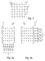
- Fig. 1 shows an example of an information code in the form of a position-coding pattern of the type that is described in WO 01/26032 that was mentioned by way of introduction.
- the position-coding pattern is constructed of marks 1, which here are the shape of circular dots. Each mark is displaced in any one of four different directions in relation to a reference position or nominal position 2, which consists of an intersection between raster lines 3 in a raster.
- the raster can be invisible, but in Fig. 1 the raster is shown by broken lines for the sake of clarity.
- Each mark 1 represents a value 0-3 depending upon in which direction the mark is displaced in relation to the nominal point 2.
- the value 0 is coded by displacement to the right, 1 by displacement upwards, 2 by displacement to the left and 3 by displacement downwards.
- the different possible values 0-3 for the marks can be expressed in binary form as bit pairs (0,1; 0,0: 1,0; and 1,1).
- the first bit in the bit pair corresponding to a mark's value is used for coding position information in the x-direction and the second bit is used for coding position information in the y-direction.
- the position coding is thus carried out separately in the x-direction and the y-direction, but the graphical coding is carried out using marks that are the same for the x-direction and the y-direction.
- Each set of 6*6 adjacent marks in the position-coding pattern codes a position in the form of an x-coordinate and a y-coordinate. More specifically, each set of 6*6 marks can be translated into a 6*6-bit matrix that codes an x-coordinate and a 6*6-bit matrix that codes a y-coordinate for the position.
- Figs 2a and 2b show an x-bit matrix 4 and a y-bit matrix 5 that were decoded from the information code in Fig. 1 .
- each sequence of bits in a column constitutes a partial sequence in a 63 bit long cyclic main number sequence that has the property that if a partial sequence is extracted that is six bits in length, this has an unambiguously determined location in the main number sequence.
- the six columns can thus be translated into six position numbers P0-P5, that correspond to six locations in the main number sequence. Between these six position numbers, five difference numbers D0-D4 can be created in pairs, which code the x-coordinate. For a certain x-coordinate, the position numbers P will vary depending upon the y-coordinate.
- the difference numbers D are, on the other hand, the same regardless of the y-coordinate, as the position numbers P always vary in accordance with the main number sequence that is repeated cyclically in the columns in the total position-coding pattern.
- six rows in the y-bit matrix define six position numbers P'0-P'5 in the main number sequence. These six position numbers define five difference numbers D'0-D'4, that code the y-coordinate.
- the difference numbers D and D' can, for example, code the x-coordinate and the y-coordinate respectively by constituting a partial sequence of an x-difference number sequence and a y-difference number sequence respectively, each of which has the property that a partial sequence consisting of five numbers has an unambiguously determined location in the difference number sequence.
- Another principle for how the difference numbers D and D' code the x-coordinate and the y-coordinate respectively is described in the above-mentioned WO 01/26032 .
- the position-coding pattern thus contains redundant information, which means that it is possible to decode positions correctly even though one or more marks are in an incorrect position in the position-coding pattern, are missing in the position-coding pattern, are decoded incorrectly or are missed during the decoding. This property can in turn be utilized for coding additional information in the position-coding pattern.
- the position-coding pattern comprises a plurality of nominal positions 2 that consist of intersections between raster lines 3 in a raster.
- these nominal.positions 2 with associated marks 1 code position information, but can also, as has been described above, code other information. Therefore in the following the term "first information code" is used instead of position-coding pattern.
- the redundancy in the first information code marks that belong to certain of the nominal positions can be omitted while retaining the ability to decode the first information code. All the marks can, of course, not be omitted, only a subset or a selection of these.
- the subset of the first information code's nominal positions for which marks can be omitted constitutes a basis for a second information code for coding additional information in addition to that which is coded by the first information code. In the following the combination of the first information code and the second information code is called just the information code.
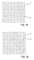
- Figs 3a and 3b show two different examples of which nominal positions 2 in the first information code can have their associated mark omitted while retaining the ability to decode the first information code.
- the nominal positions 2 that belong to the first information code are marked by circles, which can be filled in or not, while the nominal positions 6 that belong to the second information code are marked by filled-in circles.
- At least four marks can thus be omitted in each set of 8*8 marks, while in the example in Fig. 3b eight marks can be omitted in each set of 8*8 marks.
- eight marks can be omitted in each set of 8*8 marks.
- Figs 3a and 3b are just examples. With a first information code with the error-correcting properties described above, it is possible to remove marks in other arrangements or patterns than those that are shown in Figs 3a and 3b . If a first information code with other error-correcting properties is taken as a starting point, marks can, of course, be removed in other arrangements or patterns.
- the second information code can code the additional information in various ways.
- a commonplace way is to either retain or omit marks for all nominal positions 6 in the second information code. In this way, two different information values can be coded.
- Another way is to omit marks in any one of a plurality of predetermined patterns or arrangements for omitting marks in the second information code.
- the information is then coded dependent upon which of this plurality of predetermined patterns is used.
- predetermined patterns can be those that are shown in Figs 3a and 3b .
- Other examples can be based on those in Figs 3a and 3b , but where the choice is made to retain the marks in certain nominal positions, for example in half of the nominal positions in a regular pattern.
- An additional way is to omit all marks according to any one of the possible patterns for omitting marks and to code information dependent upon the relative placings of the first information code and the second information code. More specifically, the first omitted mark in the second information code and thereby all the second information code can be placed differently in relation to the origin of the first information code. This is illustrated in Fig. 3a and Fig. 4 that show two different possible relative placings of the first information code and the second information code.
- FIG. 5a shows more specifically how the first information code can be divided into fixed cells 40 that are 8*8 marks in size.
- the cells are normally not marked on the base on which the first information code has been applied, but are virtual cells. For the sake of clarity, however, they are marked in Fig. 5a by broken lines 41.
- Fig. 5a shows, in addition, the nominal positions 6 that constitute part of the second information code. These nominal positions 6 form a pattern according to Fig. 3b . Within each cell 40 there are eight nominal positions that constitute part of the second information code. If each such nominal position codes the value 0 or 1 depending upon whether the mark is present or has been omitted, each cell can code 2 8 different values, that is 256 different values.
- Cells of a different size and shape can be used.
- cells can be used with 4*8 nominal positions in the first information code, each of which then contains four nominal positions in the second information code, which can thus code 2 4 different values.
- Fig. 5b shows yet another example of division into cells 40. This example is based on Fig. 3a .
- the cells are rotated in relation to the raster for the first information code.
- each cell contains four nominal positions 6 which belong to the second information code.
- Each cell can thus code a maximum of 2 4 different values, that is 16 different values.
- the cells do not overlap each other, but are fixed in relation to the first information code, which means that their placings are simple to determine as soon as the first information code has been decoded. In this case, it is assumed, however, that the first information code codes position information.
- the placings of the cells are determined by at least one omitted dot being identified.
- the nominal positions 6 that form the basis for the second information code can be identified since their relative placing in the first information code is known.
- the coordinates that are defined for the nominal position associated with the omitted mark can be determined.
- the coordinates for a position are coded by the marks that belong to each set of 8*8 nominal positions in the first information code. These coordinates relate to the nominal position at the top left in the set.
- the coordinates for the nominal position 6 or the position of the nominal position 6 that is associated with the omitted mark can thus be determined.
- the cells 40 can be defined in any part of the information code, when an omitted mark has been identified and the coordinates for this omitted mark have been determined.
- the decoding of the first information code is based on 8*8 marks to make possible error correcting. If a decoding device records an image of the information code that does not comprise more than precisely 8*8 marks, it is not certain that the marks recorded in the image comprise a whole fixed cell for decoding the second information code. If all or most of the cells code the same value, this constitutes no problem, however, as the decoding can then be carried out on the basis of parts of several adjacent cells in the image.
- the decoding device records an image with at least 15*15 marks, a whole cell will always be included within the recorded marks.
- a cell value can be determined if required, using information from several images recorded by a decoding device.
- the second information code can code different types of information. It can be used for superimposing a second information layer on the first information layer coded by the first information code.
- the second information layer can, for example, contain height information which is related to positions on a map, which positions are coded by means of the first information code.
- the second information code can be used to indicate or activate different fields with different functions on a physical base which is provided with a first information code.
- the indication and/or activation can be carried out in a corresponding way to that described in SE 0103029-5 and SE 0201846-3 mentioned above.
- Fig. 6 shows schematically an e-mail form 60 which is divided into three different fields with different functions.
- a first field 61 is intended for message information that is to be recorded and processed only as a sequence of coordinates.
- a second field 62 is intended for address information that is to be interpreted using ICR (Intelligent Character Recognition).
- a third field 63 constitutes a so-called send box that indicates that one or more coordinates that are recorded from this area are to be interpreted as an instruction that message information recorded from the first field is to be sent to the address recorded from the second area.
- the whole e-mail form 60 is provided with the first information code.
- the three different fields can be distinguished by means of the second information code, in a corresponding way to that described in the above-mentioned SE 0103029-5 .
- the second information code can be divided into cells that code different values in the three different fields or the pattern of omitted marks can be displaced in different ways relative to the first information code in the three fields.
- the whole e-mail form 60 is thus divided into fields, which are provided with the second information code, which accordingly extends over the whole e-mail form.
- the send box 63 and address field 62 can be defined as fields that are indicated by means of the second information code, while the remaining part 61 of the form is regarded as a background where no marks are omitted and where accordingly only the first information code is to be found.
- the second information code can be position coding in a corresponding way to that described in SE 0201846-3 .
- the first information code is then suitably divided into cells, each of which codes four different values.
- the position coding can then be carried out in the way that is described in the above-mentioned WO 01/26032 , whereby the cells with their four different possible values correspond to the marks in WO 01/26032 .
- the second information code then codes coordinates for points in a second coordinate system or on a second imaginary surface so that the position information can be separated from the position information that is coded by the first information code.
- the number of cells that code coordinates for a point in the second coordinate system can be considerably less than the number of marks in the first information code that code coordinates for a point.
- the so-called pen point displacement problem can be solved.
- the pen point and the sensor can be displaced in relation to each other. It can then occur that the user points with the pen point in one field with a particular function, but that the sensor, due to the displacement, records the information code in another field. If the second information code is position coding and extends outside the actual field, the decoding device can determine where the pen point is located and whether it is inside or outside the actual field.
- the information code described above can be applied on a physical base or product. It can, for example, be printed out on a sheet of paper.
- the coding device which for example can be realized by means of an ordinary personal computer, comprises a processing unit 70 which in addition to the actual processor 71 comprises a working memory 72 and a program memory 73 which stores a program for producing the information code.
- the coding device comprises, in addition, an input means 74 which makes it possible for a user to input information into the processor concerning a required layout for the information code on a physical base.
- the input means 74 can, for example, be a keyboard or a mouse or some other corresponding input unit that is normally used together with a computer.
- a unit 75 can be connected to the coding device which, on the basis of a digital representation of an information code, applies a graphical representation of the information code on a product.
- the unit can, for example, consist of a printer that prints out the information code on a sheet of paper or alternatively be some form of printing device.
- a first step 80 the processor 71 in the coding device receives an indication entered by the user of which coordinate area is to be coded by the first information code.
- the indication can consist of a selection from predefined coordinate areas or an explicit indication of an area in the form of, for example, a pair of coordinates defining the top left corner of the area and a width and a height on the page.
- space is allocated in the working memory 72 for storage of a digital representation of the information code.
- the processor thereafter calculates a value that indicates the placing of the mark, in step 81. How such a calculation can be carried out is described in the above-mentioned WO 01/26032 .
- the value of the respective mark is stored in a first matrix in the working memory 72.
- the value can, for example, be given as a number between 0 and 3, where 0 means that the mark is displaced to the right from its nominal position, 1 that it is displaced upwards, 2 that it is displaced to the left and 3 that it is displaced downwards.
- the processor 71 receives an indication of at least one field of a certain type that is to be indicated by means of the second information code and the placing of this field within the coordinate area that is coded by the first information code, step 82.
- the processor determines a second matrix that defines the cell values for the indicated field or fields.
- the indicated fields can, as has been described above, cover all or a part of the coordinate area that is to be coded by the first information code.
- the second matrix constitutes the input signal to the next step in the coding.
- the processor 71 determines, on the basis of the cell values defined in the second matrix and in accordance with a predetermined algorithm that states how the cell values are coded, whether each of the marks that correspond to nominal positions in the second information code is to remain in the information code or is to be omitted, step 83. More specifically, the processor determines a third matrix that is the same size as the first matrix, in which it allocates the marks that are to be omitted the value 4 and the other marks the value 0.
- a fourth matrix is created as the sum of the first matrix and the third matrix. Marks that are to be found in the information code have a value in the fourth matrix that codes their placing. Marks that are to be omitted have a value that is 4 or higher.
- the information code can be printed out if so required, using the printer 75.
- the fourth matrix can, for example, be sent to a program that generates a PostScript file for printout on the printer.
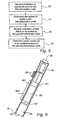
- Fig. 9 shows an example of how a hand-held user unit which can be used as a decoding device, can be realized. It comprises a casing 91 which is approximately the same shape as a pen. In the end of the casing there is an opening 92. The end is intended to abut against or to be held a short distance from the surface from which the position-coding pattern is to be recorded.
- the casing contains principally an optics part, an electronic circuitry part and a power supply.
- the optics part comprises at least one light-emitting diode 93 for illuminating a partial area of the surface with the information code and a light-sensitive area sensor 94, for example a CCD or CMOS sensor, for recording a two-dimensional image of the information code on the surface.
- a light-sensitive area sensor 94 for example a CCD or CMOS sensor, for recording a two-dimensional image of the information code on the surface.
- the device can also contain an optical system, such as a mirror and/or lens system.
- the light-emitting diode can be an infrared light-emitting diode and the sensor can be sensitive to infrared light.
- the power supply for the device is obtained from a battery 95, which is mounted in a separate compartment in the casing. It is also possible to provide the power supply via a cable from an external power source (not shown).
- the electronic circuitry part contains a processing unit 96 with a processor which is programmed to record images from the sensor 94 and to decode the information code in these images, plus a working memory and a program memory.
- the processor can be programmed to carry out certain operations on the basis of the decoded information.
- the processor can, for example, send information to a specific address that is included in the decoded information, as a result of it interpreting and processing the decoded information.
- information is stored in the user unit which makes it possible for this to determine how the decoded information is to be processed/interpreted.
- the information can, for example, include which fields are coded by which cell values and/or by which displacements of the second information code relative to the first information code and/or by which specific patterns of omitted marks.
- the user unit also comprises a pen point 97, with the aid of which the user can write ordinary pigment-based writing on a base from which the coding pattern is to be recorded.
- the pen point 97 is extendable and retractable so that the user can control whether or not it is to be used. In certain applications, the user unit does not need to have a pen point at all.
- the pigment-based writing is suitably of a type that is transparent, that is non-absorbent, to infrared light and the marks suitably absorb infrared light.
- the detection of the pattern can be carried out without the above-mentioned writing interfering with the pattern.
- the user unit can also comprise buttons 98, by means of which the device can be activated and controlled. It also has a transceiver 99 for wireless transmission of information to and from the device, for example using infrared light, radio waves or ultrasound.
- the user unit 2 can also comprise a display 900 for displaying recorded and/or processed information.
- the user unit can be divided between different physical casings, with a first casing containing components which are required for recording images of the coding pattern and for transmitting these to components which are contained in a second casing and which decode the coding pattern in the recorded image or images.
- a first step 100 the processor unit 96 in the user unit receives a digital representation of the information code that the sensor 94 recorded locally at the end of the user unit.
- the processor unit 96 thereafter decodes the first information code by identifying the marks in the digital representation, determining the virtual raster and the placing of the marks in relation to this and by calculating a pair of coordinates, step 101, on the basis of the placing of a predetermined number, for example 8*8, of the identified marks.
- the decoding of the first information code comprises error correction of the nominal positions 6 that do not have marks because they are in the second information code. A more detailed description of how the first information code can be decoded is to be found in WO 01/26032 .
- the processor unit 96 can determine, in step 102, how the cells that are used for the decoding of the second information code are placed, since the placing of the cells is fixed in relation to the first information code.
- the processor unit can, in addition, determine which nominal positions 6 in the second information code belong to the respective cells and it can thus determine which of these nominal positions have an associated mark and which do not have an associated mark and thereby determine the cell value, step 103, for example by means of a table that is stored in the memory of the user unit.
- the cell value can be given directly by an omitted mark coding a first bit value and a mark that is present coding a second bit value, the cell value being determined from the combination of bit values. Steps 102 and 103 thus correspond to a decoding of the second information code.
- the processor unit determines that the cell value corresponds to the "send" box 63, the pair of coordinates will be processed as an instruction to send previously stored message information to an address that was ICR interpreted from the second field 62.
- the description of which fields are coded by the different cell values can be stored in the memory of the user unit.
- the description above is based on decoding of the second information code when this codes information by means of cell values. If the second information code instead codes information by a predetermined pattern of omitted marks being displaced in various ways in relation to the first information code, then the processor unit 96 instead detects one or more nominal positions 2 in the first information code that do not have marks. With knowledge of the pattern for omission of marks, the processor unit 96 can thereafter calculate how the second information code is displaced relative to the first information code. More specifically, the processor unit 96 determines the positions of the omitted marks in relation to the origin and determines from these what value is coded by the second information code.
- the processor unit 96 can, for example, determine whether the pattern of omitted dots is the one shown in Fig. 3a or 3b , or some other predetermined pattern and thereby determine what value is coded by the second information code.
- the second information code can also code information on the basis of a combination of cell values and pattern displacement.
- the information codes described above have a raster that creates a square grid. This is not necessary.
- the raster can, for example, be triangular or hexagonal, with the nominal positions consisting of points where the raster lines intersect.
- each mark is coded by its placing in relation to a reference point.
- other parameters such as the shape or colour or size of the mark, can be used ' to code the value of the mark.
Abstract
Description
- The present invention relates to a product which is provided with a first information code that is arranged to redundantly code a first information element by means of a plurality of marks. The invention also relates to methods and devices for coding and decoding an information code.
- In addition, the invention relates to a product with an information code that cannot be copied while retaining its functionality and a method for producing such a product.
- It is already known that handwriting can be digitised by determining how a pen that is used to produce the handwriting is being moved. One way of carrying this out is to use a base for the handwriting that is provided with a position-coding pattern that codes coordinates for points on the base and also to provide the pen with a sensor that records the position-coding pattern locally at the pen point while the pen is being moved across the base. A processing unit, that can be placed in the pen or remotely from this, can thereafter decode the recorded position-coding pattern, so that the movement of the pen across the base can be determined as a series of coordinates.
- In
WO 01/26032 - Using the position-coding pattern in the above-mentioned
WO 01/26032 -
WO 01/71653 WO 01/26032 -
WO 01/48685 WO 01/26032 WO 01/48685 - In order to make possible flexible information processing, different parties may want to have bases with different functions associated with different fields, with different numbers of fields, with differently placed fields and with differently sized fields. For this purpose, the processing unit may need to store a large number of different digital templates, which in addition may need to be updated and supplemented, as different parties want to create new bases.
- This can constitute a problem, particularly if the processing unit has limited memory capacity and/or if it is time-consuming to amend, supplement and/or update the digital templates once these have been stored in the processing unit. This can, for example, be the case if the processing unit is in a portable user unit, such as the pen in
WO 01/48685 - In the Swedish patent application
SE 0103029-5 US 2003/066896 ,WO 03/042912 EP 1 444 646 - The additional information can alternatively be used to indicate in the coding pattern on the physical base whether a particular field in a digital template with several alternative fields is activated or not. By digital templates being combined so that in each digital template there is a description of a large number of alternatively useable fields and by the fields used in each individual case being activated by means of the coding of additional information in the coding pattern on the physical base, the number of digital templates required can be reduced.
- The indication or activation of fields is achieved by the coding pattern in the different fields being divided into cells, each of which comprises a plurality of marks, and by each of the cells being allocated a predetermined value by means of the variation in the second parameter.
- In the Swedish patent application
SE 0201846-3 US 2005/145703 ,WO 03/107265 EP 1 532 577 -
EP 0764944 A2 discloses an information recording medium, on which multimedia information is recorded as an optical readable code. The code is divided into blocks, where each block has a data dot pattern and markers, which serve as reference points for the data dots in the data dot pattern. The dots in the data dot pattern include pattern dots, address dots and data dots, which are provided in different areas of the data dot pattern. - The claims are delimited against this document.
- The invention is defined by the claims. A first object of the present invention is to propose a solution to the problem described above, namely that many digital templates are required to allow flexible information processing.
- As there is a redundancy in the first information code, it is possible to decode the first information element even if one or more marks are missing. This property is utilized in the invention in such a way that at least one mark is intentionally omitted with the aim of coding at least one additional information element.
- The additional information element or elements can, for example, be utilized to indicate or activate fields on a base that is provided with a position-coding pattern for digital recording of handwriting.
- In the following, the present invention will be described in greater detail by way of examples, with reference to the accompanying drawings, in which
-
Fig. 1 shows schematically a known first information code. -
Figs 2a and 2b show the first information code decoded into a bit matrix that codes an x-coordinate and a bit matrix that codes a y-coordinate. -
Figs 3a and 3b show schematically two examples of patterns in accordance with which marks can be omitted in the first information code shown.inFig. 1 without the decodability thereof being lost. -
Fig. 4 shows the same pattern as inFig. 3a for omitting marks, but the pattern is displaced in another way in relation to the first information code. -
Figs 5a and5b show how the information code inFig. 3b and 3a respectively can be divided into cells. -
Fig. 6 shows a form in which different fields can be indicated by the omission of marks. -
Fig. 7 is a schematic block diagram for a coding device for coding an information code. -
Fig. 8 is a flow chart that shows how an information code can be coded. -
Fig. 9 shows schematically a user unit that can be used for decoding an information code. -
Fig. 10 is a flow chart that shows how an information code can be decoded. - In the following, an example of a known information code in which the present invention can be utilised is first described with reference to
Figs 1 and 2 . There follows a description with reference toFigs 3-10 of how additional information can be coded in this information code by the omission of marks in the code. -
Fig. 1 shows an example of an information code in the form of a position-coding pattern of the type that is described inWO 01/26032 marks 1, which here are the shape of circular dots. Each mark is displaced in any one of four different directions in relation to a reference position ornominal position 2, which consists of an intersection betweenraster lines 3 in a raster. The raster can be invisible, but inFig. 1 the raster is shown by broken lines for the sake of clarity. - Each
mark 1 represents a value 0-3 depending upon in which direction the mark is displaced in relation to thenominal point 2. Thevalue 0 is coded by displacement to the right, 1 by displacement upwards, 2 by displacement to the left and 3 by displacement downwards. The different possible values 0-3 for the marks can be expressed in binary form as bit pairs (0,1; 0,0: 1,0; and 1,1). The first bit in the bit pair corresponding to a mark's value is used for coding position information in the x-direction and the second bit is used for coding position information in the y-direction. The position coding is thus carried out separately in the x-direction and the y-direction, but the graphical coding is carried out using marks that are the same for the x-direction and the y-direction. - Each set of 6*6 adjacent marks in the position-coding pattern codes a position in the form of an x-coordinate and a y-coordinate. More specifically, each set of 6*6 marks can be translated into a 6*6-bit matrix that codes an x-coordinate and a 6*6-bit matrix that codes a y-coordinate for the position.
Figs 2a and 2b show anx-bit matrix 4 and a y-bit matrix 5 that were decoded from the information code inFig. 1 . - In addition, consider the
x-bit matrix 4. This can be divided into six columns, each with six bits. Each sequence of bits in a column constitutes a partial sequence in a 63 bit long cyclic main number sequence that has the property that if a partial sequence is extracted that is six bits in length, this has an unambiguously determined location in the main number sequence. The six columns can thus be translated into six position numbers P0-P5, that correspond to six locations in the main number sequence. Between these six position numbers, five difference numbers D0-D4 can be created in pairs, which code the x-coordinate. For a certain x-coordinate, the position numbers P will vary depending upon the y-coordinate. The difference numbers D are, on the other hand, the same regardless of the y-coordinate, as the position numbers P always vary in accordance with the main number sequence that is repeated cyclically in the columns in the total position-coding pattern. - In a corresponding way, six rows in the y-bit matrix define six position numbers P'0-P'5 in the main number sequence. These six position numbers define five difference numbers D'0-D'4, that code the y-coordinate.
- The difference numbers D and D' can, for example, code the x-coordinate and the y-coordinate respectively by constituting a partial sequence of an x-difference number sequence and a y-difference number sequence respectively, each of which has the property that a partial sequence consisting of five numbers has an unambiguously determined location in the difference number sequence. Another principle for how the difference numbers D and D' code the x-coordinate and the y-coordinate respectively is described in the above-mentioned
WO 01/26032 - Even though in principle no more than 6*6 marks are required for defining a position, 8*8 marks are used advantageously for the decoding. The fact is that the above-mentioned 63 bit long main number sequence can be designed in such a way that none of the 8 bit long partial sequences that are included in the main number sequence occurs backwards and inverted or with one bit inverted in the main number sequence. This property of the main number sequence can be used to determine how a recorded image of the position-coding pattern, which, after all, looks essentially identical whether it is rotated through 0, 90, 180 or 270 degrees, is oriented. In addition, it can be used to correct an incorrectly decoded bit in an eight-bit long column or row in the x- or y-
bit matrix - With decoding using 8*8 marks, the position-coding pattern thus contains redundant information, which means that it is possible to decode positions correctly even though one or more marks are in an incorrect position in the position-coding pattern, are missing in the position-coding pattern, are decoded incorrectly or are missed during the decoding. This property can in turn be utilized for coding additional information in the position-coding pattern.
- As mentioned above, the position-coding pattern comprises a plurality of
nominal positions 2 that consist of intersections betweenraster lines 3 in a raster. In this example, thesenominal.positions 2 with associatedmarks 1 code position information, but can also, as has been described above, code other information. Therefore in the following the term "first information code" is used instead of position-coding pattern. - Thanks to the redundancy in the first information code, marks that belong to certain of the nominal positions can be omitted while retaining the ability to decode the first information code. All the marks can, of course, not be omitted, only a subset or a selection of these. The number of marks that can be omitted and for which nominal positions are determined by the error-correcting properties of the first information code. The subset of the first information code's nominal positions for which marks can be omitted constitutes a basis for a second information code for coding additional information in addition to that which is coded by the first information code. In the following the combination of the first information code and the second information code is called just the information code.
-
Figs 3a and 3b show two different examples of whichnominal positions 2 in the first information code can have their associated mark omitted while retaining the ability to decode the first information code. Thenominal positions 2 that belong to the first information code are marked by circles, which can be filled in or not, while thenominal positions 6 that belong to the second information code are marked by filled-in circles. - In the example in
Fig. 3a , at least four marks can thus be omitted in each set of 8*8 marks, while in the example inFig. 3b eight marks can be omitted in each set of 8*8 marks. In neither case is more than one mark of eight consecutive marks in a row or a column omitted as the error-correcting properties of the first information code are such that a maximum of one bit error in eight bits can be corrected. - It should be pointed out that the examples in
Figs 3a and 3b are just examples. With a first information code with the error-correcting properties described above, it is possible to remove marks in other arrangements or patterns than those that are shown inFigs 3a and 3b . If a first information code with other error-correcting properties is taken as a starting point, marks can, of course, be removed in other arrangements or patterns. - The second information code can code the additional information in various ways.
- A commonplace way is to either retain or omit marks for all
nominal positions 6 in the second information code. In this way, two different information values can be coded. - Another way is to omit marks in any one of a plurality of predetermined patterns or arrangements for omitting marks in the second information code. The information is then coded dependent upon which of this plurality of predetermined patterns is used. Examples of predetermined patterns can be those that are shown in
Figs 3a and 3b . Other examples can be based on those inFigs 3a and 3b , but where the choice is made to retain the marks in certain nominal positions, for example in half of the nominal positions in a regular pattern. - An additional way is to omit all marks according to any one of the possible patterns for omitting marks and to code information dependent upon the relative placings of the first information code and the second information code. More specifically, the first omitted mark in the second information code and thereby all the second information code can be placed differently in relation to the origin of the first information code. This is illustrated in
Fig. 3a andFig. 4 that show two different possible relative placings of the first information code and the second information code. - Yet another way is to divide the first information code into cells, and let information be coded by the absence and presence of marks in the cells in the nominal positions that belong to the second information code.
Fig. 5a shows more specifically how the first information code can be divided into fixedcells 40 that are 8*8 marks in size. The cells are normally not marked on the base on which the first information code has been applied, but are virtual cells. For the sake of clarity, however, they are marked inFig. 5a bybroken lines 41. -
Fig. 5a shows, in addition, thenominal positions 6 that constitute part of the second information code. Thesenominal positions 6 form a pattern according toFig. 3b . Within eachcell 40 there are eight nominal positions that constitute part of the second information code. If each such nominal position codes thevalue - Cells of a different size and shape can be used. In
Fig. 5a , for example, cells can be used with 4*8 nominal positions in the first information code, each of which then contains four nominal positions in the second information code, which can thus code 24 different values. -
Fig. 5b shows yet another example of division intocells 40. This example is based onFig. 3a . In this example, the cells are rotated in relation to the raster for the first information code. In addition, each cell contains fournominal positions 6 which belong to the second information code. Each cell can thus code a maximum of 24 different values, that is 16 different values. - As shown in
Fig. 5a , the cells do not overlap each other, but are fixed in relation to the first information code, which means that their placings are simple to determine as soon as the first information code has been decoded. In this case, it is assumed, however, that the first information code codes position information. - In the case shown in
Fig. 5b , the placings of the cells are determined by at least one omitted dot being identified. On the basis of this dot, thenominal positions 6 that form the basis for the second information code can be identified since their relative placing in the first information code is known. In addition, the coordinates that are defined for the nominal position associated with the omitted mark can be determined. As has been described above, the coordinates for a position are coded by the marks that belong to each set of 8*8 nominal positions in the first information code. These coordinates relate to the nominal position at the top left in the set. The coordinates for thenominal position 6 or the position of thenominal position 6 that is associated with the omitted mark can thus be determined. As the rotation of the cells and their placing in relation to the first information code is known, thecells 40 can be defined in any part of the information code, when an omitted mark has been identified and the coordinates for this omitted mark have been determined. - The decoding of the first information code is based on 8*8 marks to make possible error correcting. If a decoding device records an image of the information code that does not comprise more than precisely 8*8 marks, it is not certain that the marks recorded in the image comprise a whole fixed cell for decoding the second information code. If all or most of the cells code the same value, this constitutes no problem, however, as the decoding can then be carried out on the basis of parts of several adjacent cells in the image.
- If the decoding device records an image with at least 15*15 marks, a whole cell will always be included within the recorded marks. In addition, a cell value can be determined if required, using information from several images recorded by a decoding device.
- The second information code can code different types of information. It can be used for superimposing a second information layer on the first information layer coded by the first information code. The second information layer can, for example, contain height information which is related to positions on a map, which positions are coded by means of the first information code.
- In addition, the second information code can be used to indicate or activate different fields with different functions on a physical base which is provided with a first information code. The indication and/or activation can be carried out in a corresponding way to that described in
SE 0103029-5 SE 0201846-3 -
Fig. 6 shows schematically ane-mail form 60 which is divided into three different fields with different functions. Afirst field 61 is intended for message information that is to be recorded and processed only as a sequence of coordinates. Asecond field 62 is intended for address information that is to be interpreted using ICR (Intelligent Character Recognition). Athird field 63 constitutes a so-called send box that indicates that one or more coordinates that are recorded from this area are to be interpreted as an instruction that message information recorded from the first field is to be sent to the address recorded from the second area. - The
whole e-mail form 60 is provided with the first information code. The three different fields can be distinguished by means of the second information code, in a corresponding way to that described in the above-mentionedSE 0103029-5 whole e-mail form 60 is thus divided into fields, which are provided with the second information code, which accordingly extends over the whole e-mail form. According to another alternative, thesend box 63 andaddress field 62 can be defined as fields that are indicated by means of the second information code, while the remainingpart 61 of the form is regarded as a background where no marks are omitted and where accordingly only the first information code is to be found. - As yet another example, the second information code can be position coding in a corresponding way to that described in
SE 0201846-3 WO 01/26032 WO 01/26032 - The information code described above can be applied on a physical base or product. It can, for example, be printed out on a sheet of paper.
- Now follows a description of how the coding of the information code can be carried out in a coding device, which is illustrated schematically in
Fig. 7 . The coding device, which for example can be realized by means of an ordinary personal computer, comprises aprocessing unit 70 which in addition to theactual processor 71 comprises a workingmemory 72 and aprogram memory 73 which stores a program for producing the information code. The coding device comprises, in addition, an input means 74 which makes it possible for a user to input information into the processor concerning a required layout for the information code on a physical base. The input means 74 can, for example, be a keyboard or a mouse or some other corresponding input unit that is normally used together with a computer. In addition, aunit 75 can be connected to the coding device which, on the basis of a digital representation of an information code, applies a graphical representation of the information code on a product. The unit can, for example, consist of a printer that prints out the information code on a sheet of paper or alternatively be some form of printing device. - With reference to the flow chart in
Fig. 8 , there now follows a description of how the coding can be carried out in the case when the additional information is coded by the first information code being divided into cells and by these being allocated values for indication of different fields. - In a
first step 80, theprocessor 71 in the coding device receives an indication entered by the user of which coordinate area is to be coded by the first information code. The indication can consist of a selection from predefined coordinate areas or an explicit indication of an area in the form of, for example, a pair of coordinates defining the top left corner of the area and a width and a height on the page. In association with this step, space is allocated in the workingmemory 72 for storage of a digital representation of the information code. For each mark that is included in the information code, the processor thereafter calculates a value that indicates the placing of the mark, instep 81. How such a calculation can be carried out is described in the above-mentionedWO 01/26032 memory 72. The value can, for example, be given as a number between 0 and 3, where 0 means that the mark is displaced to the right from its nominal position, 1 that it is displaced upwards, 2 that it is displaced to the left and 3 that it is displaced downwards. - After this the
processor 71 receives an indication of at least one field of a certain type that is to be indicated by means of the second information code and the placing of this field within the coordinate area that is coded by the first information code,step 82. - On the basis of the indication in
step 82, the processor determines a second matrix that defines the cell values for the indicated field or fields. The indicated fields can, as has been described above, cover all or a part of the coordinate area that is to be coded by the first information code. The second matrix constitutes the input signal to the next step in the coding. In the following step, theprocessor 71 determines, on the basis of the cell values defined in the second matrix and in accordance with a predetermined algorithm that states how the cell values are coded, whether each of the marks that correspond to nominal positions in the second information code is to remain in the information code or is to be omitted,step 83. More specifically, the processor determines a third matrix that is the same size as the first matrix, in which it allocates the marks that are to be omitted thevalue 4 and the other marks thevalue 0. - Finally, a fourth matrix is created as the sum of the first matrix and the third matrix. Marks that are to be found in the information code have a value in the fourth matrix that codes their placing. Marks that are to be omitted have a value that is 4 or higher.
- When the coding is completed, the information code can be printed out if so required, using the
printer 75. The fourth matrix can, for example, be sent to a program that generates a PostScript file for printout on the printer. -
Fig. 9 shows an example of how a hand-held user unit which can be used as a decoding device, can be realized. It comprises acasing 91 which is approximately the same shape as a pen. In the end of the casing there is anopening 92. The end is intended to abut against or to be held a short distance from the surface from which the position-coding pattern is to be recorded. - The casing contains principally an optics part, an electronic circuitry part and a power supply.
- The optics part comprises at least one light-emitting
diode 93 for illuminating a partial area of the surface with the information code and a light-sensitive area sensor 94, for example a CCD or CMOS sensor, for recording a two-dimensional image of the information code on the surface. If required, the device can also contain an optical system, such as a mirror and/or lens system. The light-emitting diode can be an infrared light-emitting diode and the sensor can be sensitive to infrared light. - The power supply for the device is obtained from a
battery 95, which is mounted in a separate compartment in the casing. It is also possible to provide the power supply via a cable from an external power source (not shown). - The electronic circuitry part contains a
processing unit 96 with a processor which is programmed to record images from thesensor 94 and to decode the information code in these images, plus a working memory and a program memory. In addition, the processor can be programmed to carry out certain operations on the basis of the decoded information. The processor can, for example, send information to a specific address that is included in the decoded information, as a result of it interpreting and processing the decoded information. - For this purpose, information is stored in the user unit which makes it possible for this to determine how the decoded information is to be processed/interpreted. The information can, for example, include which fields are coded by which cell values and/or by which displacements of the second information code relative to the first information code and/or by which specific patterns of omitted marks.
- In this embodiment, the user unit also comprises a
pen point 97, with the aid of which the user can write ordinary pigment-based writing on a base from which the coding pattern is to be recorded. Thepen point 97 is extendable and retractable so that the user can control whether or not it is to be used. In certain applications, the user unit does not need to have a pen point at all. - The pigment-based writing is suitably of a type that is transparent, that is non-absorbent, to infrared light and the marks suitably absorb infrared light. By using a light-emitting diode which emits infrared light and a sensor which is sensitive to infrared light, the detection of the pattern can be carried out without the above-mentioned writing interfering with the pattern.
- The user unit can also comprise
buttons 98, by means of which the device can be activated and controlled. It also has atransceiver 99 for wireless transmission of information to and from the device, for example using infrared light, radio waves or ultrasound. Theuser unit 2 can also comprise adisplay 900 for displaying recorded and/or processed information. - The user unit can be divided between different physical casings, with a first casing containing components which are required for recording images of the coding pattern and for transmitting these to components which are contained in a second casing and which decode the coding pattern in the recorded image or images.
- An example of how the decoding of the information code described above can be carried out will now be described with reference to the flow chart in
Fig. 10 . The example is based on the second information code coding information by means of cell values and on the information code that covers the base comprising the second information code. - In a
first step 100, theprocessor unit 96 in the user unit receives a digital representation of the information code that thesensor 94 recorded locally at the end of the user unit. Theprocessor unit 96 thereafter decodes the first information code by identifying the marks in the digital representation, determining the virtual raster and the placing of the marks in relation to this and by calculating a pair of coordinates,step 101, on the basis of the placing of a predetermined number, for example 8*8, of the identified marks. The decoding of the first information code comprises error correction of thenominal positions 6 that do not have marks because they are in the second information code. A more detailed description of how the first information code can be decoded is to be found inWO 01/26032 WO 01/26034 WO 01/75783 SE 0104088-0 US 2005/199729 ,US 2003/122855 ,WO 03/049023 EP 1 456 811 - When the first information code has been decoded, the
processor unit 96 can determine, instep 102, how the cells that are used for the decoding of the second information code are placed, since the placing of the cells is fixed in relation to the first information code. When the placing of the cells has been determined, the processor unit can, in addition, determine whichnominal positions 6 in the second information code belong to the respective cells and it can thus determine which of these nominal positions have an associated mark and which do not have an associated mark and thereby determine the cell value,step 103, for example by means of a table that is stored in the memory of the user unit. Alternatively, the cell value can be given directly by an omitted mark coding a first bit value and a mark that is present coding a second bit value, the cell value being determined from the combination of bit values.Steps - When the second information code has been decoded, the
processor unit 96 can determine which field is coded by the second information code,step 104. It thereafter processes the pair of coordinates in a way that depends upon the detected field,step 105. If, for example, the cell value corresponds to thefirst field 61 in thee-mail form 60 inFig. 6 , the pair of coordinates decoded from the first information code is processed in the memory as a pair of coordinates belonging to a normal pen stroke on the surface. If instead, theprocessor unit 96 determines that the cell value corresponds to thesecond field 62, then the pair of coordinates will be stored for later ICR interpretation (ICR = Intelligent Character Recognition). If, finally, the processor unit determines that the cell value corresponds to the "send"box 63, the pair of coordinates will be processed as an instruction to send previously stored message information to an address that was ICR interpreted from thesecond field 62. The description of which fields are coded by the different cell values can be stored in the memory of the user unit. - The description above is based on decoding of the second information code when this codes information by means of cell values. If the second information code instead codes information by a predetermined pattern of omitted marks being displaced in various ways in relation to the first information code, then the
processor unit 96 instead detects one or morenominal positions 2 in the first information code that do not have marks. With knowledge of the pattern for omission of marks, theprocessor unit 96 can thereafter calculate how the second information code is displaced relative to the first information code. More specifically, theprocessor unit 96 determines the positions of the omitted marks in relation to the origin and determines from these what value is coded by the second information code. - If the second information code instead codes information by the use of one of a plurality of predetermined patterns for the omission of marks, then the processor unit detects which
nominal positions 2 do not have marks in the first information code. As a result, theprocessor unit 96 can, for example, determine whether the pattern of omitted dots is the one shown inFig. 3a or 3b , or some other predetermined pattern and thereby determine what value is coded by the second information code. - The second information code can also code information on the basis of a combination of cell values and pattern displacement.
- It has been described above how additional information can be coded in an information code by the omission of marks. The description has been given with reference to a special information code. The idea can, however, be applied to other types of information codes which redundantly code at least one first information element by means of a plurality of marks. Examples of such other information codes are to be found in, for instance,
WO 00/73983 WO 99/50787 US 6,208,771 . - The information codes described above have a raster that creates a square grid. This is not necessary. The raster can, for example, be triangular or hexagonal, with the nominal positions consisting of points where the raster lines intersect.
- In the description above, the value of each mark is coded by its placing in relation to a reference point. In other applicable information codes other parameters, such as the shape or colour or size of the mark, can be used ' to code the value of the mark.
Claims (24)
- A product which is provided with a first information code, which is arranged to redundantly code at least one first information element by means of a plurality of marks (1), and which comprises a plurality of first reference positions (2),
each of said plurality of marks being associated with one of said first reference positions
characterised in that
the product is further provided with a second information code that comprises a plurality of second reference positions (6), which constitute a selection from said plurality of first reference positions (2),
wherein at least one additional information element, which is different from the first information element, is coded by the second information code by at least one of said plurality of second reference positions not having an associated mark. - A product according to claim 1, wherein the first reference positions define a first virtual raster, which has first raster lines (3) and in which the first reference positions (2) consist of points at which the first raster lines intersect.
- A product according to claim 1 or 2, wherein said at least one additional information element is coded by how said plurality of second reference positions (6) are placed in relation to said plurality of first reference positions (2).
- A product according to claim 1, wherein each second reference position (6) in the second information code represents a first value if it has an associated mark and a second value if it does not have an associated mark.
- A product according to claim 4, wherein the second reference positions form at least one cell (40) with at least two second reference positions (6) and wherein said at least one cell has a cell value that is determined by which values are represented by the second reference positions included in the cell.
- A product according to claim 5, wherein said at least one cell (40) has a fixed placing in relation to the first information code.
- A product according to claim 5 or 6, wherein said at least one additional information element is coded by the cell value of said at least one cell (40).
- A product according to any one of the preceding claims, wherein said at least one additional information element represents a position.
- A product according to any one of the preceding claims, wherein said at least one first information element represents a position.
- A product according to any one of the preceding claims, wherein said at least one first information element is coded by means of variation of a parameter for the marks, said parameter being one of the following: placing of the mark, shape of the mark, colour of the mark and size of the mark.
- A product according to any one of the preceding claims, wherein the value of each mark is coded by its placing in relation to the reference position with which it is associated.
- A product according to any one of the preceding claims, wherein each mark is displaced in one of four different directions from the reference position with which it is associated in order to code a value from 0-3.
- A method for decoding a first and a second information code, comprising
locating a plurality of marks (1) in a digital representation of the first and the second information code;
determining a plurality of first reference positions (2) for the marks, each of said plurality of located marks being associated with one reference position;
determining the values of the located marks for decoding at least one first information element coded by the first information code;
characterised in that the method further comprising
identifying a plurality of second reference positions (6), which constitute a selection from said first reference positions (2); and
decoding at least one additional information element coded by the second information code by identifying at least one of said second reference positions (6) that does not have an associated mark. - A method according to claim 13, further comprising decoding the at least one additional information element by identifying how said plurality of second reference positions (6) is placed in relation to said plurality of first reference positions (2).
- A method according to claim 13, wherein each second reference position (6) in the second information code represents a first value if it has an associated mark and a second value if it does not have an associated mark.
- A method according to claim 15, further comprising identifying at least one cell (40) including at least two second reference positions (6), and decoding a cell value from the values represented by the second reference positions of the cell.
- A method according to claim 16, wherein the cell (40) is identified based on its fixed placing in relation to the first information code.
- A method according to claim 16 or 17, wherein said at least one additional information element is coded by the cell value of said at least one cell (40).
- A method according to any one of claims 13-18, wherein said at least one additional information element represents a position.
- A method according to any one of claims 13-19, wherein said at least one first information element represents a position.
- A method according to any one of claims 13-20, wherein the step of determining the values of the located marks comprises determining the placing of each of the located marks in relation to the reference point with which it is associated.
- A method according to any one of claims 13-21, wherein the step of determining the values of the located marks comprises determining, for each one of the located marks, a value from 0-3 depending on in which one of four different directions from the reference point with which it is associated the located mark is displaced.
- A computer program, which comprises program code that is arranged to carry out a method according to any one of claims 13-22 when it is executed by a computer.
- A device for decoding an information code,
characterised by a processing unit (70) which is arranged to carry out a method according to any one of claims 13-22.
Applications Claiming Priority (3)
| Application Number | Priority Date | Filing Date | Title |
|---|---|---|---|
| SE0203853A SE0203853D0 (en) | 2002-12-23 | 2002-12-23 | Data code |
| SE0203853 | 2002-12-23 | ||
| PCT/SE2003/001687 WO2004057526A1 (en) | 2002-12-23 | 2003-10-31 | Information code including redundant information providing copy protection |
Publications (2)
| Publication Number | Publication Date |
|---|---|
| EP1579379A1 EP1579379A1 (en) | 2005-09-28 |
| EP1579379B1 true EP1579379B1 (en) | 2010-07-28 |
Family
ID=20290001
Family Applications (1)
| Application Number | Title | Priority Date | Filing Date |
|---|---|---|---|
| EP03759160A Expired - Lifetime EP1579379B1 (en) | 2002-12-23 | 2003-10-31 | Information code including redundant information providing copy protection |
Country Status (8)
| Country | Link |
|---|---|
| US (1) | US7600693B2 (en) |
| EP (1) | EP1579379B1 (en) |
| JP (1) | JP4707395B2 (en) |
| AT (1) | ATE475947T1 (en) |
| AU (1) | AU2003275755A1 (en) |
| DE (1) | DE60333591D1 (en) |
| SE (1) | SE0203853D0 (en) |
| WO (1) | WO2004057526A1 (en) |
Families Citing this family (24)
| Publication number | Priority date | Publication date | Assignee | Title |
|---|---|---|---|---|
| MXPA05003310A (en) | 2002-09-26 | 2005-10-18 | Yoshida Kenji | Information reproduction/i/o method using dot pattern, information reproduction device, mobile information i/o device, and electronic toy. |
| US7364091B2 (en) | 2003-12-19 | 2008-04-29 | Scientific Games International, Inc. | Embedded optical signatures in documents |
| US7252222B2 (en) * | 2003-12-19 | 2007-08-07 | Scientific Game Royalty Corporation | Embedded optical signatures in documents |
| SE0401647D0 (en) * | 2004-06-28 | 2004-06-28 | Anoto Ab | Coding and decoding of data |
| US11627944B2 (en) | 2004-11-30 | 2023-04-18 | The Regents Of The University Of California | Ultrasound case builder system and method |
| BRPI0419251A (en) * | 2004-12-28 | 2007-12-18 | Kenji Yoshida | method of generating information output using a dot pattern |
| US20060163354A1 (en) * | 2005-01-21 | 2006-07-27 | Tyranski Robert P | System and method of product identification, authentication and verification |
| CA2606135C (en) | 2005-04-28 | 2015-06-30 | Kenji Yoshida | Information input/output method using dot pattern |
| US8074891B2 (en) | 2005-06-17 | 2011-12-13 | Anoto Ab | Coding and decoding methods and apparatuses |
| JP3771252B1 (en) | 2005-07-01 | 2006-04-26 | 健治 吉田 | Dot pattern |
| KR100841285B1 (en) * | 2006-09-18 | 2008-06-25 | 주식회사 펜래버레토리 | Product having Absolute Positioning Code Pattern on a surface thereof and Method for generating Absolute Positioning Code Pattern |
| US20100084468A1 (en) * | 2008-10-02 | 2010-04-08 | Silverbrook Research Pty Ltd | Method of imaging coding pattern comprising columns and rows of coordinate data |
| TWI492162B (en) * | 2011-05-25 | 2015-07-11 | Generalplus Technology Inc | Two-dimentional optical indetification device with same gray level |
| US9566560B2 (en) | 2011-10-06 | 2017-02-14 | Illumina, Inc. | Array domains having rotated patterns |
| CN104246673A (en) * | 2012-04-26 | 2014-12-24 | 松下电器产业株式会社 | Display control system, display device, and display panel |
| CN102708349B (en) * | 2012-05-11 | 2014-11-05 | 深圳市天朗时代科技有限公司 | Method for decoding matrix two-dimensional code |
| US11631342B1 (en) | 2012-05-25 | 2023-04-18 | The Regents Of University Of California | Embedded motion sensing technology for integration within commercial ultrasound probes |
| CN103748536A (en) * | 2012-05-31 | 2014-04-23 | 松下电器产业株式会社 | Reader device for position code and reading method |
| US10380919B2 (en) | 2013-11-21 | 2019-08-13 | SonoSim, Inc. | System and method for extended spectrum ultrasound training using animate and inanimate training objects |
| US10380920B2 (en) | 2013-09-23 | 2019-08-13 | SonoSim, Inc. | System and method for augmented ultrasound simulation using flexible touch sensitive surfaces |
| US11600201B1 (en) | 2015-06-30 | 2023-03-07 | The Regents Of The University Of California | System and method for converting handheld diagnostic ultrasound systems into ultrasound training systems |
| US10896628B2 (en) | 2017-01-26 | 2021-01-19 | SonoSim, Inc. | System and method for multisensory psychomotor skill training |
| US11810473B2 (en) | 2019-01-29 | 2023-11-07 | The Regents Of The University Of California | Optical surface tracking for medical simulation |
| US11495142B2 (en) | 2019-01-30 | 2022-11-08 | The Regents Of The University Of California | Ultrasound trainer with internal optical tracking |
Family Cites Families (25)
| Publication number | Priority date | Publication date | Assignee | Title |
|---|---|---|---|---|
| US5145518A (en) | 1990-06-27 | 1992-09-08 | Xerox Corporation | Inks containing block copolymer micelles |
| US5225900A (en) | 1990-12-31 | 1993-07-06 | Xerox Corporation | Method of storing information within a reproduction system |
| US5271764A (en) | 1992-02-12 | 1993-12-21 | Xerox Corporation | Ink compositions |
| US5286286A (en) | 1991-05-16 | 1994-02-15 | Xerox Corporation | Colorless fast-drying ink compositions for printing concealed images detectable by fluorescence |
| US5208630A (en) | 1991-11-04 | 1993-05-04 | Xerox Corporation | Process for the authentication of documents utilizing encapsulated toners |
| US5256193A (en) | 1992-06-25 | 1993-10-26 | Xerox Corporation | Porphyrin chromophore and dendrimer ink composition |
| EP1298579A1 (en) | 1992-09-28 | 2003-04-02 | Olympus Optical Co., Ltd. | Information recording medium, information reproducing device and information reproducing method |
| US5291243A (en) | 1993-02-05 | 1994-03-01 | Xerox Corporation | System for electronically printing plural-color tamper-resistant documents |
| JPH0981711A (en) * | 1995-09-20 | 1997-03-28 | Olympus Optical Co Ltd | Information recording medium, information reproduction system, and information recording the system |
| JPH1091746A (en) * | 1996-09-10 | 1998-04-10 | Toppan Printing Co Ltd | Copying preventive code and printed matter |
| US5937110A (en) | 1996-12-20 | 1999-08-10 | Xerox Corporation | Parallel propagating embedded binary sequences for characterizing objects in N-dimensional address space |
| WO1999050751A1 (en) | 1998-04-01 | 1999-10-07 | Xerox Corporation | Routing document identifiers |
| AUPQ363299A0 (en) | 1999-10-25 | 1999-11-18 | Silverbrook Research Pty Ltd | Paper based information inter face |
| AU5263300A (en) | 1999-05-28 | 2000-12-18 | Anoto Ab | Position determination |
| SE517445C2 (en) * | 1999-10-01 | 2002-06-04 | Anoto Ab | Position determination on a surface provided with a position coding pattern |
| WO2001048685A1 (en) | 1999-12-23 | 2001-07-05 | Anoto Ab | General information management system |
| US20030141375A1 (en) * | 2000-03-09 | 2003-07-31 | Spectra Systems Corporation | Information bearing marking used with a digitally watermarked background |
| SE518962C2 (en) | 2000-03-21 | 2002-12-10 | Anoto Ab | Product and method for encoding data into a matrix-shaped coding pattern |
| DE60142468D1 (en) | 2000-04-05 | 2010-08-12 | Anoto Ab | IDENTIFYING A VIRTUAL GRID PATTERN |
| WO2002064380A1 (en) | 2001-02-15 | 2002-08-22 | Mitsubishi Pencil Kabushikikaisha | Writing implement |
| SE523378C2 (en) | 2001-05-29 | 2004-04-13 | Ibusiness Ab | System and method for simultaneous signing of a record in paper and digital form |
| SE520045C2 (en) | 2001-09-13 | 2003-05-13 | Anoto Ab | Coding Patterns |
| US7175095B2 (en) | 2001-09-13 | 2007-02-13 | Anoto Ab | Coding pattern |
| SE520682C2 (en) | 2001-12-06 | 2003-08-12 | Anoto Ab | Reconstruction of a virtual screen |
| DE60325064D1 (en) | 2002-06-18 | 2009-01-15 | Anoto Ab | POSITION CODING PATTERN |
-
2002
- 2002-12-23 SE SE0203853A patent/SE0203853D0/en unknown
-
2003
- 2003-10-31 AU AU2003275755A patent/AU2003275755A1/en not_active Abandoned
- 2003-10-31 EP EP03759160A patent/EP1579379B1/en not_active Expired - Lifetime
- 2003-10-31 JP JP2004562169A patent/JP4707395B2/en not_active Expired - Fee Related
- 2003-10-31 US US10/516,592 patent/US7600693B2/en active Active
- 2003-10-31 DE DE60333591T patent/DE60333591D1/en not_active Expired - Lifetime
- 2003-10-31 AT AT03759160T patent/ATE475947T1/en not_active IP Right Cessation
- 2003-10-31 WO PCT/SE2003/001687 patent/WO2004057526A1/en active Application Filing
Also Published As
| Publication number | Publication date |
|---|---|
| JP4707395B2 (en) | 2011-06-22 |
| SE0203853D0 (en) | 2002-12-23 |
| US20050173533A1 (en) | 2005-08-11 |
| ATE475947T1 (en) | 2010-08-15 |
| US7600693B2 (en) | 2009-10-13 |
| EP1579379A1 (en) | 2005-09-28 |
| JP2006511864A (en) | 2006-04-06 |
| DE60333591D1 (en) | 2010-09-09 |
| WO2004057526A1 (en) | 2004-07-08 |
| AU2003275755A1 (en) | 2004-07-14 |
Similar Documents
| Publication | Publication Date | Title |
|---|---|---|
| EP1579379B1 (en) | Information code including redundant information providing copy protection | |
| US7175095B2 (en) | Coding pattern | |
| EP1532577B1 (en) | Position-coding pattern | |
| US6666376B1 (en) | Calendar | |
| US6689966B2 (en) | System and method for determining positional information | |
| US6586688B2 (en) | Information-related devices and methods | |
| KR101236809B1 (en) | Method and system for combining a position and information code | |
| JP4658427B2 (en) | Encoded paper for optical reading | |
| JP2003528388A (en) | Document processing | |
| US8418052B2 (en) | Processing of documents | |
| EP2133824A2 (en) | Position code | |
| EP1444646B1 (en) | Product with a coding pattern and method, device and computer program for coding and decoding the pattern | |
| US20080235282A1 (en) | Personal Computing Apparatus and a Method Therein | |
| US7559484B2 (en) | Products with data encoding pattern | |
| EP1269396B1 (en) | Apparatus and methods relating to images |
Legal Events
| Date | Code | Title | Description |
|---|---|---|---|
| PUAI | Public reference made under article 153(3) epc to a published international application that has entered the european phase |
Free format text: ORIGINAL CODE: 0009012 |
|
| 17P | Request for examination filed |
Effective date: 20050725 |
|
| AK | Designated contracting states |
Kind code of ref document: A1 Designated state(s): AT BE BG CH CY CZ DE DK EE ES FI FR GB GR HU IE IT LI LU MC NL PT RO SE SI SK TR |
|
| AX | Request for extension of the european patent |
Extension state: AL LT LV MK |
|
| DAX | Request for extension of the european patent (deleted) | ||
| RAP1 | Party data changed (applicant data changed or rights of an application transferred) |
Owner name: ANOTO AB |
|
| 17Q | First examination report despatched |
Effective date: 20070213 |
|
| RAP1 | Party data changed (applicant data changed or rights of an application transferred) |
Owner name: ANOTO AB |
|
| GRAP | Despatch of communication of intention to grant a patent |
Free format text: ORIGINAL CODE: EPIDOSNIGR1 |
|
| GRAS | Grant fee paid |
Free format text: ORIGINAL CODE: EPIDOSNIGR3 |
|
| GRAA | (expected) grant |
Free format text: ORIGINAL CODE: 0009210 |
|
| AK | Designated contracting states |
Kind code of ref document: B1 Designated state(s): AT BE BG CH CY CZ DE DK EE ES FI FR GB GR HU IE IT LI LU MC NL PT RO SE SI SK TR |
|
| REG | Reference to a national code |
Ref country code: GB Ref legal event code: FG4D |
|
| REG | Reference to a national code |
Ref country code: CH Ref legal event code: EP |
|
| REG | Reference to a national code |
Ref country code: IE Ref legal event code: FG4D |
|
| REF | Corresponds to: |
Ref document number: 60333591 Country of ref document: DE Date of ref document: 20100909 Kind code of ref document: P |
|
| REG | Reference to a national code |
Ref country code: NL Ref legal event code: VDEP Effective date: 20100728 |
|
| PG25 | Lapsed in a contracting state [announced via postgrant information from national office to epo] |
Ref country code: NL Free format text: LAPSE BECAUSE OF FAILURE TO SUBMIT A TRANSLATION OF THE DESCRIPTION OR TO PAY THE FEE WITHIN THE PRESCRIBED TIME-LIMIT Effective date: 20100728 Ref country code: AT Free format text: LAPSE BECAUSE OF FAILURE TO SUBMIT A TRANSLATION OF THE DESCRIPTION OR TO PAY THE FEE WITHIN THE PRESCRIBED TIME-LIMIT Effective date: 20100728 Ref country code: FI Free format text: LAPSE BECAUSE OF FAILURE TO SUBMIT A TRANSLATION OF THE DESCRIPTION OR TO PAY THE FEE WITHIN THE PRESCRIBED TIME-LIMIT Effective date: 20100728 |
|
| PG25 | Lapsed in a contracting state [announced via postgrant information from national office to epo] |
Ref country code: CY Free format text: LAPSE BECAUSE OF FAILURE TO SUBMIT A TRANSLATION OF THE DESCRIPTION OR TO PAY THE FEE WITHIN THE PRESCRIBED TIME-LIMIT Effective date: 20100728 Ref country code: SI Free format text: LAPSE BECAUSE OF FAILURE TO SUBMIT A TRANSLATION OF THE DESCRIPTION OR TO PAY THE FEE WITHIN THE PRESCRIBED TIME-LIMIT Effective date: 20100728 Ref country code: BG Free format text: LAPSE BECAUSE OF FAILURE TO SUBMIT A TRANSLATION OF THE DESCRIPTION OR TO PAY THE FEE WITHIN THE PRESCRIBED TIME-LIMIT Effective date: 20101028 Ref country code: PT Free format text: LAPSE BECAUSE OF FAILURE TO SUBMIT A TRANSLATION OF THE DESCRIPTION OR TO PAY THE FEE WITHIN THE PRESCRIBED TIME-LIMIT Effective date: 20101129 |
|
| PG25 | Lapsed in a contracting state [announced via postgrant information from national office to epo] |
Ref country code: GR Free format text: LAPSE BECAUSE OF FAILURE TO SUBMIT A TRANSLATION OF THE DESCRIPTION OR TO PAY THE FEE WITHIN THE PRESCRIBED TIME-LIMIT Effective date: 20101029 Ref country code: SE Free format text: LAPSE BECAUSE OF FAILURE TO SUBMIT A TRANSLATION OF THE DESCRIPTION OR TO PAY THE FEE WITHIN THE PRESCRIBED TIME-LIMIT Effective date: 20100728 Ref country code: BE Free format text: LAPSE BECAUSE OF FAILURE TO SUBMIT A TRANSLATION OF THE DESCRIPTION OR TO PAY THE FEE WITHIN THE PRESCRIBED TIME-LIMIT Effective date: 20100728 |
|
| PG25 | Lapsed in a contracting state [announced via postgrant information from national office to epo] |
Ref country code: DK Free format text: LAPSE BECAUSE OF FAILURE TO SUBMIT A TRANSLATION OF THE DESCRIPTION OR TO PAY THE FEE WITHIN THE PRESCRIBED TIME-LIMIT Effective date: 20100728 |
|
| PG25 | Lapsed in a contracting state [announced via postgrant information from national office to epo] |
Ref country code: MC Free format text: LAPSE BECAUSE OF NON-PAYMENT OF DUE FEES Effective date: 20101031 Ref country code: CZ Free format text: LAPSE BECAUSE OF FAILURE TO SUBMIT A TRANSLATION OF THE DESCRIPTION OR TO PAY THE FEE WITHIN THE PRESCRIBED TIME-LIMIT Effective date: 20100728 Ref country code: EE Free format text: LAPSE BECAUSE OF FAILURE TO SUBMIT A TRANSLATION OF THE DESCRIPTION OR TO PAY THE FEE WITHIN THE PRESCRIBED TIME-LIMIT Effective date: 20100728 Ref country code: IT Free format text: LAPSE BECAUSE OF FAILURE TO SUBMIT A TRANSLATION OF THE DESCRIPTION OR TO PAY THE FEE WITHIN THE PRESCRIBED TIME-LIMIT Effective date: 20100728 Ref country code: RO Free format text: LAPSE BECAUSE OF FAILURE TO SUBMIT A TRANSLATION OF THE DESCRIPTION OR TO PAY THE FEE WITHIN THE PRESCRIBED TIME-LIMIT Effective date: 20100728 Ref country code: SK Free format text: LAPSE BECAUSE OF FAILURE TO SUBMIT A TRANSLATION OF THE DESCRIPTION OR TO PAY THE FEE WITHIN THE PRESCRIBED TIME-LIMIT Effective date: 20100728 |
|
| REG | Reference to a national code |
Ref country code: CH Ref legal event code: PL |
|
| PLBE | No opposition filed within time limit |
Free format text: ORIGINAL CODE: 0009261 |
|
| STAA | Information on the status of an ep patent application or granted ep patent |
Free format text: STATUS: NO OPPOSITION FILED WITHIN TIME LIMIT |
|
| PG25 | Lapsed in a contracting state [announced via postgrant information from national office to epo] |
Ref country code: ES Free format text: LAPSE BECAUSE OF FAILURE TO SUBMIT A TRANSLATION OF THE DESCRIPTION OR TO PAY THE FEE WITHIN THE PRESCRIBED TIME-LIMIT Effective date: 20101108 |
|
| 26N | No opposition filed |
Effective date: 20110429 |
|
| PG25 | Lapsed in a contracting state [announced via postgrant information from national office to epo] |
Ref country code: LI Free format text: LAPSE BECAUSE OF NON-PAYMENT OF DUE FEES Effective date: 20101031 Ref country code: CH Free format text: LAPSE BECAUSE OF NON-PAYMENT OF DUE FEES Effective date: 20101031 |
|
| REG | Reference to a national code |
Ref country code: DE Ref legal event code: R097 Ref document number: 60333591 Country of ref document: DE Effective date: 20110429 |
|
| PG25 | Lapsed in a contracting state [announced via postgrant information from national office to epo] |
Ref country code: IE Free format text: LAPSE BECAUSE OF NON-PAYMENT OF DUE FEES Effective date: 20101031 |
|
| PG25 | Lapsed in a contracting state [announced via postgrant information from national office to epo] |
Ref country code: HU Free format text: LAPSE BECAUSE OF FAILURE TO SUBMIT A TRANSLATION OF THE DESCRIPTION OR TO PAY THE FEE WITHIN THE PRESCRIBED TIME-LIMIT Effective date: 20110129 Ref country code: LU Free format text: LAPSE BECAUSE OF NON-PAYMENT OF DUE FEES Effective date: 20101031 |
|
| PG25 | Lapsed in a contracting state [announced via postgrant information from national office to epo] |
Ref country code: TR Free format text: LAPSE BECAUSE OF FAILURE TO SUBMIT A TRANSLATION OF THE DESCRIPTION OR TO PAY THE FEE WITHIN THE PRESCRIBED TIME-LIMIT Effective date: 20100728 |
|
| PGFP | Annual fee paid to national office [announced via postgrant information from national office to epo] |
Ref country code: FR Payment date: 20121018 Year of fee payment: 10 Ref country code: DE Payment date: 20121024 Year of fee payment: 10 |
|
| REG | Reference to a national code |
Ref country code: DE Ref legal event code: R119 Ref document number: 60333591 Country of ref document: DE Effective date: 20140501 |
|
| REG | Reference to a national code |
Ref country code: FR Ref legal event code: ST Effective date: 20140630 |
|
| PG25 | Lapsed in a contracting state [announced via postgrant information from national office to epo] |
Ref country code: FR Free format text: LAPSE BECAUSE OF NON-PAYMENT OF DUE FEES Effective date: 20131031 Ref country code: DE Free format text: LAPSE BECAUSE OF NON-PAYMENT OF DUE FEES Effective date: 20140501 |
|
| PGFP | Annual fee paid to national office [announced via postgrant information from national office to epo] |
Ref country code: GB Payment date: 20161026 Year of fee payment: 14 |
|
| GBPC | Gb: european patent ceased through non-payment of renewal fee |
Effective date: 20171031 |
|
| PG25 | Lapsed in a contracting state [announced via postgrant information from national office to epo] |
Ref country code: GB Free format text: LAPSE BECAUSE OF NON-PAYMENT OF DUE FEES Effective date: 20171031 |