EP1578668B1 - Apparatus and methods for wire-tying bundles of objects - Google Patents
Apparatus and methods for wire-tying bundles of objects Download PDFInfo
- Publication number
- EP1578668B1 EP1578668B1 EP03810768A EP03810768A EP1578668B1 EP 1578668 B1 EP1578668 B1 EP 1578668B1 EP 03810768 A EP03810768 A EP 03810768A EP 03810768 A EP03810768 A EP 03810768A EP 1578668 B1 EP1578668 B1 EP 1578668B1
- Authority
- EP
- European Patent Office
- Prior art keywords
- wire
- feed
- wheel
- tension
- guide
- Prior art date
- Legal status (The legal status is an assumption and is not a legal conclusion. Google has not performed a legal analysis and makes no representation as to the accuracy of the status listed.)
- Expired - Lifetime
Links
- 238000000034 method Methods 0.000 title description 15
- 230000007246 mechanism Effects 0.000 claims abstract description 119
- 230000000153 supplemental effect Effects 0.000 claims description 17
- 239000000919 ceramic Substances 0.000 claims description 13
- 238000012546 transfer Methods 0.000 claims description 13
- 238000009825 accumulation Methods 0.000 claims description 9
- 125000006850 spacer group Chemical group 0.000 claims description 5
- 238000001514 detection method Methods 0.000 claims description 3
- 238000003780 insertion Methods 0.000 claims description 3
- 230000037431 insertion Effects 0.000 claims description 3
- 239000002184 metal Substances 0.000 claims description 3
- 238000011144 upstream manufacturing Methods 0.000 claims description 2
- 238000000429 assembly Methods 0.000 abstract description 10
- 230000000712 assembly Effects 0.000 abstract description 9
- 239000002699 waste material Substances 0.000 abstract description 5
- 238000004891 communication Methods 0.000 abstract description 2
- 241001589086 Bellapiscis medius Species 0.000 description 111
- 230000033001 locomotion Effects 0.000 description 20
- 230000006870 function Effects 0.000 description 12
- 238000005520 cutting process Methods 0.000 description 11
- 230000008901 benefit Effects 0.000 description 7
- 239000000969 carrier Substances 0.000 description 7
- 238000010586 diagram Methods 0.000 description 6
- 230000001965 increasing effect Effects 0.000 description 6
- 239000012530 fluid Substances 0.000 description 5
- 238000003860 storage Methods 0.000 description 5
- 230000007704 transition Effects 0.000 description 5
- 238000012423 maintenance Methods 0.000 description 4
- 239000000463 material Substances 0.000 description 4
- 229910001315 Tool steel Inorganic materials 0.000 description 3
- 239000003638 chemical reducing agent Substances 0.000 description 3
- 230000008878 coupling Effects 0.000 description 3
- 238000010168 coupling process Methods 0.000 description 3
- 238000005859 coupling reaction Methods 0.000 description 3
- 230000000977 initiatory effect Effects 0.000 description 3
- 238000010008 shearing Methods 0.000 description 3
- 229910000831 Steel Inorganic materials 0.000 description 2
- 208000027418 Wounds and injury Diseases 0.000 description 2
- 230000008859 change Effects 0.000 description 2
- 230000006835 compression Effects 0.000 description 2
- 238000007906 compression Methods 0.000 description 2
- 230000003993 interaction Effects 0.000 description 2
- 238000004519 manufacturing process Methods 0.000 description 2
- 230000004044 response Effects 0.000 description 2
- 239000010959 steel Substances 0.000 description 2
- 230000001133 acceleration Effects 0.000 description 1
- 230000009471 action Effects 0.000 description 1
- 238000013459 approach Methods 0.000 description 1
- 230000015572 biosynthetic process Effects 0.000 description 1
- 230000015556 catabolic process Effects 0.000 description 1
- 238000005352 clarification Methods 0.000 description 1
- 239000002131 composite material Substances 0.000 description 1
- 230000001143 conditioned effect Effects 0.000 description 1
- 238000010276 construction Methods 0.000 description 1
- 230000001351 cycling effect Effects 0.000 description 1
- 230000006378 damage Effects 0.000 description 1
- 230000009849 deactivation Effects 0.000 description 1
- 230000000881 depressing effect Effects 0.000 description 1
- 238000007599 discharging Methods 0.000 description 1
- 230000008030 elimination Effects 0.000 description 1
- 238000003379 elimination reaction Methods 0.000 description 1
- 238000005516 engineering process Methods 0.000 description 1
- 230000002708 enhancing effect Effects 0.000 description 1
- 230000007613 environmental effect Effects 0.000 description 1
- 238000000605 extraction Methods 0.000 description 1
- 238000012840 feeding operation Methods 0.000 description 1
- 230000004907 flux Effects 0.000 description 1
- 208000014674 injury Diseases 0.000 description 1
- 238000002955 isolation Methods 0.000 description 1
- 238000003754 machining Methods 0.000 description 1
- 230000007257 malfunction Effects 0.000 description 1
- -1 metallic Substances 0.000 description 1
- 238000003801 milling Methods 0.000 description 1
- 238000012986 modification Methods 0.000 description 1
- 230000004048 modification Effects 0.000 description 1
- 230000007935 neutral effect Effects 0.000 description 1
- 230000003287 optical effect Effects 0.000 description 1
- 239000010893 paper waste Substances 0.000 description 1
- 230000002093 peripheral effect Effects 0.000 description 1
- 238000003825 pressing Methods 0.000 description 1
- 230000008569 process Effects 0.000 description 1
- 230000009467 reduction Effects 0.000 description 1
- 230000000717 retained effect Effects 0.000 description 1
- 239000004065 semiconductor Substances 0.000 description 1
- 230000035939 shock Effects 0.000 description 1
- 238000007514 turning Methods 0.000 description 1
- 239000011800 void material Substances 0.000 description 1
- 239000002023 wood Substances 0.000 description 1
Images


Classifications
-
- B—PERFORMING OPERATIONS; TRANSPORTING
- B65—CONVEYING; PACKING; STORING; HANDLING THIN OR FILAMENTARY MATERIAL
- B65B—MACHINES, APPARATUS OR DEVICES FOR, OR METHODS OF, PACKAGING ARTICLES OR MATERIALS; UNPACKING
- B65B13/00—Bundling articles
- B65B13/18—Details of, or auxiliary devices used in, bundling machines or bundling tools
- B65B13/22—Means for controlling tension of binding means
-
- B—PERFORMING OPERATIONS; TRANSPORTING
- B65—CONVEYING; PACKING; STORING; HANDLING THIN OR FILAMENTARY MATERIAL
- B65B—MACHINES, APPARATUS OR DEVICES FOR, OR METHODS OF, PACKAGING ARTICLES OR MATERIALS; UNPACKING
- B65B13/00—Bundling articles
- B65B13/02—Applying and securing binding material around articles or groups of articles, e.g. using strings, wires, strips, bands or tapes
- B65B13/04—Applying and securing binding material around articles or groups of articles, e.g. using strings, wires, strips, bands or tapes with means for guiding the binding material around the articles prior to severing from supply
- B65B13/06—Stationary ducts or channels
-
- B—PERFORMING OPERATIONS; TRANSPORTING
- B65—CONVEYING; PACKING; STORING; HANDLING THIN OR FILAMENTARY MATERIAL
- B65B—MACHINES, APPARATUS OR DEVICES FOR, OR METHODS OF, PACKAGING ARTICLES OR MATERIALS; UNPACKING
- B65B13/00—Bundling articles
- B65B13/18—Details of, or auxiliary devices used in, bundling machines or bundling tools
- B65B13/184—Strap accumulators
-
- B—PERFORMING OPERATIONS; TRANSPORTING
- B65—CONVEYING; PACKING; STORING; HANDLING THIN OR FILAMENTARY MATERIAL
- B65B—MACHINES, APPARATUS OR DEVICES FOR, OR METHODS OF, PACKAGING ARTICLES OR MATERIALS; UNPACKING
- B65B13/00—Bundling articles
- B65B13/18—Details of, or auxiliary devices used in, bundling machines or bundling tools
- B65B13/24—Securing ends of binding material
- B65B13/28—Securing ends of binding material by twisting
Definitions
- This invention relates to apparatus and methods for wire-tying one or more objects, including, for example, wood products, newspapers, magazines, pulp bales, waste paper bales, rag bales, pipe, or other mechanical elements.
- the wire-tying machines disclosed by these references typically include a track that surrounds a bundling station where a bundle of objects may be positioned, a feed assembly for feeding a length of wire about the track, a gripping assembly for securing a free end of the length of wire after it has been fed about the track, a tensioning assembly for pulling the length of wire tightly about the bundle of objects, a twisting assembly for tying or otherwise coupling the length of wire to form a wire loop around the bundle of objects, a cutting assembly for cutting the length of wire from a wire supply, and an ejector for ejecting the wire loop from the machine.
- Such hydraulic or pneumatic actuation systems require relatively expensive cylinder and piston actuators, pressurized lines, pumps, valves, and fluid storage facilities. These components not only add to the initial cost of the wire-tying machine, but also require considerable maintenance. The handling, storage, disposal, and cleanup of fluids used in typical hydraulic systems also presents issues related to safety and environmental regulations.
- Prior art document WO 01/68450 A2 relates to an apparatus and method for wire-tying one or more objects.
- This apparatus for bundling one or more objects comprises a track assembly, a feed and tension assembly and a twist assembly having a gripping mechanism.
- the gripping mechanism includes a gripper block having a wire receptacle formed therein, an opposing wall positioned approximate to the wire receptacle and a gripper member constrained to move and frictionally engagable with the length of the wire disposed within the wire receptacle, the gripper member being driven by a frictional engagement with the length of wire and pinching the length of wire against the opposing wall when the drive motor is operated in the tension direction.
- an apparatus in one aspect of the invention, includes a track assembly, a feed and tension assembly, and a twister assembly having a gripping mechanism engageable with the length of wire, a twisting mechanism including a twisting motor operatively coupled to a twist pinion engageable with the length of wire, the twist pinion being rotatable to twist a portion of the length of wire to form a knot, a cutting mechanism engageable with the length of wire proximate the knot, and an ejecting mechanism engageable with the length of wire to disengage the length of wire from the twister assembly.
- the gripping mechanism includes a gripper block having a wire receptacle formed therein, an opposing wall positioned proximate the wire receptacle, and a gripper disc constrained to move toward the opposing wall to frictionally engage with the length of wire disposed within the wire receptacle, the gripper disc being driven into frictional engagement with the length of wire and pinching the length of wire against the opposing wall when the drive motor is operated in the tension direction.
- the wire is secured using a simple, passive, economical, and easily maintained gripping mechanism.
- a unique passive wire gripping sub-assembly includes a wire receptacle having a slot sized to receive a first passage of wire in one portion thereof and a second passage of wire in another portion thereof, a passive gripper disk being frictionally engageable with the second passage of wire to hold the free end of the wire.
- the assembly includes a multi-purpose cam rotatably driven by the twister motor, and the gripping mechanism includes a gripper release engageable with the gripper disk and actuatable by the multi-purpose cam.
- a unique feature of the track assembly includes multiple ceramic or high hardness steel sections or segments disposed proximate to a corner guide at the corners of the track assembly, the sections each having a curved face at least partially surrounding the wire guide path to redirect the motion of the length of wire about the corners.
- the sections resist gouging from the relatively sharp free end of the length of wire as it is guided along the wire path, reducing mis-feeds, improving reliability, and enhancing durability of the apparatus.
- the sections are less expensive to manufacture for replacement and, by adding more sections to larger corner guides, the corner radius of the wire path may be increased with little cost increase.
- an apparatus in one aspect of the invention, includes a track assembly, a feed and tension assembly, and a twister assembly having a twist motor coupled to a rotatable twist axle having a first multi-purpose cam, an ejector cam, a drive gear, and a second multi-purpose cam attached thereto, a gripping mechanism engageable with the length of wire and having a gripper cam follower engageable with the second multi-purpose cam, the gripping mechanism being actuatable by the second multi-purpose cam, a twisting mechanism having a twist pinion engageable with the length of wire, the twist pinion being actuatable by the drive gear and rotatable to twist a portion of the length of wire to form a knot, a cutting mechanism engageable with the length of wire proximate the knot and having a cutting cam follower engageable with the first multi-purpose cam, the cutting mechanism being actuatable by the first multi-purpose cam; and an ejecting mechanism engageable with the length of wire to disengage the length of wire from the twister assembly
- Another aspect of the invention is a unique wire accumulation drum through which the length of wire is axially fed and from which the length of wire tangentially exits at its periphery to be engaged by a drive wheel.
- the accumulator drum is shown in alternative forms.
- Another aspect of the invention is a unique feed and tension assembly pulling wire axially through a drum, then tangentially off the drum to a feed drive wheel and then back onto the periphery of the drum when tensioning the wire.
- Alternative forms are shown.
- Another aspect of the invention is a simple shaft driven drive for twisting the wire, gripping the wire, releasing the twisted wire, and cutting the wire.
- Another aspect of the invention is a passive wire gripper that uses the friction of the wire to cause the wire free end to be squeezed and held against movement out of the twister mechanism.
- the passive wire gripper has several alternative forms.
- Figure 1 is a front isometric view of a wire-tying machine 100 in accordance with an embodiment of the invention.
- Figures 2 and 3 are front partial sectional and back elevational views, respectively, of the wire-tying machine 100 of Figure 1 .
- the wire-tying machine 100 has several major assemblies, including a feed and tension assembly 200, a twister assembly 300, a track assembly 400, and a control system 500.
- the wire-tying machine 100 includes a housing 130 that structurally supports and/or encloses the major subassemblies of the machine.
- the overall operation of the wire-tying machine 100 begins with the feed and tension assembly 200 drawing a length of wire 102 from an external wire supply 104 (e.g., a spool or reel, not shown) into the wire-tying machine 100 past the ring sensor 412.
- the length of wire 102 is then fed by depressing a manual feed button switch actuator, whereupon, the free end of the length of wire 102 is pushed through the twister assembly 300, into and about the track assembly 400, and back into the twister assembly 300.
- the track assembly 400 forms a wire guide path 402 that substantially surrounds a bundling station 106 where one or more objects may be positioned for bundling.
- the control system 500 signals the feed and tension assembly 200 to tension the length of wire 102 about the one or more objects.
- the feed and tension assembly 200 pulls the length of wire 102 in a direction opposite the feed direction.
- the track assembly 400 opens releasing the length of wire 102 from the wire guide path 402, allowing the length of wire 102 to be drawn tightly about the one or more objects within the bundling station 106.
- An excess length of wire 114 is retracted back into the feed and tension assembly 200 and accumulated about the accumulator drum 222 until the control system 500 signals the feed and tension assembly 200 to stop tensioning, as described more fully below.
- the twister assembly 300 joins the free end 108 of the length of wire 102b to an adjacent portion of the length of wire 102a forming a fixed constricting wire loop 116 about the one or more objects forming a bundle 120.
- the wire loop 116 is secured by twisting the free end of the length of wire 102b and the adjacent portion of the length of wire 102a about one another to form a knot 118.
- the twister assembly 300 then severs the knot 118, and the formed wire loop 116, from the length of wire 102.
- the twister assembly 300 then ejects the knot 118 and returns all components of the twister assembly 300 to the home position.
- a feed cycle is subsequently initiated, at which time, the bundle 120 may be removed from the bundling station 106. All succeeding feed cycles will thus re-feed any accumulated wire 102 from about the accumulator drum 222 prior to again drawing sufficient added wire 102 from the external wire source 104 (not shown) to complete said feed cycles, until the external wire source 104 has been depleted and the load cycle must be repeated.
- the overall sequence of cycles may be reinitiated.
- the load cycle there are five operational cycles utilized by the wire-tying machine 100: the load cycle, the feed cycle, the tension cycle, the twist cycle, and the wire reject cycle.
- the wire tying machine 100 may be operated in a manual mode or in an automatic mode.
- the feed, tension, and twist cycles normally operate in the automatic mode, but may be operated in the manual mode, for example, for maintenance and clearing wire from the machine. These cycles may also overlap at various points in the operation.
- the load and wire reject cycles are usually operated in the manual mode only.
- the five operational cycles and the two operating modes of the wire-tying machine 100 are described in greater detail below.
- FIG 4 is a front isometric view of the feed and tension assembly 200 of the wire-tying machine 100 of Figure 1 .
- the feed and tension assembly 200 includes an accumulator subassembly 220, a drive subassembly 240, and a stop block subassembly 280.
- the accumulator subassembly 220 provides greater capacity than that necessary to accumulate all of the length of wire 102 fed into the largest wire-tying machine currently envisioned.
- the drive subassembly 240 provides the driving force requisite for feeding and tensioning the length of wire 102.
- the interaction between the accumulator subassembly 220 and the drive subassembly 240 produce a compressive impingement upon the length of wire 102 which efficiently transfers the driving force frictionally into the length of wire 102.
- the stop block subassembly 260 indexes the accumulator subassembly 220 in its neutral home position and damps the motion of the accumulator drum 222 at the transition between feeding the length of wire 102 from the accumulator drum 222 to feeding the length of wire 102 from the external wire source 104.
- the stop block subassembly 280 may be incorporated into the accumulator subassembly 220 and the drive subassembly 240, as shown in Figure 4A .
- Figure 5 is an exploded isometric view of the accumulator subassembly 220 of the feed and tension assembly 200 of Figure 4 .
- Figure 6 is an exploded isometric view of the drive assembly 240 of the feed and tension assembly 200 of Figure 4 .
- Figure 7 is an exploded isometric view of the stop block subassembly 280 of the feed and tension assembly 200 of Figure 4 .
- Figure 8 is an isometric view of a wire feed path 202 of the feed and tension assembly 200 of Figure 4 .
- the accumulator subassembly 200 includes an accumulator drum 222 mounted on an accumulator hub 223 that is concentrically supported on an accumulator axle 224.
- a wire inlet tube 225 is disposed through the center of the accumulator axle 224, and a wire passage 227 is disposed in the accumulator drum 222.
- the wire enters the drum axially.
- a continuous helical groove 229 is disposed within an outer surface of the accumulator drum 222, and a stop finger 231 is attached to a lateral edge of the accumulator drum 222.
- a bearing block 226 houses a pair of accumulator bearings 228 that rotatably support the accumulator axle 224 in cantilevered fashion.
- a pair of supports 230 are pivotably coupled to the bearing block 226 and to a mounting plate 232 that is secured to the housing 130, allowing the accumulator drum 222 to move laterally (side-to-side) within the housing 130 during the feeding and tensioning of the length of wire 102.
- the drum 222 can be mounted on an axle 224a, that is rotatably mounted on supports 230 that are on either side of the accumulator drum rather than on one side as in Figure 4 .
- the supports are pivotally mounted in mounting plates 232 that have bearings 228 that are swing mounted on pins 231.
- the drum can be freely swung transversely along its rotational axis to allow the wire to wrap into the helical groove 229 on the drum.
- the feeding of wire axially through the hub of the accumulation drum and then tangentially out to the drive wheel as shown in both embodiments is a unique feature of the invention. It provides for fast delivery of the wire to the track and fast and easy accumulation of the wire free from kinking or buckling as in other accumulating techniques.
- the drum also eliminates the need for prior art type accumulation compartments that need to be re-sized when tracks get larger for larger bundles.
- a transverse wheel or transverse guide wheel 234 is affixed to the accumulator hub 223 adjacent to the wire inlet tube 225.
- a tangent guide wheel 236 is mounted on a one-way clutch 238 that is also affixed to the accumulator hub 223. The clutch 238 restricts rotation of the tangent guide wheel 236 to the feed direction only.
- a tangent pinch roller 239 is springably biased against the tangent guide wheel 236.
- the length of wire 102 is passed into and through the wire inlet tube 225 during the initial feed cycle (load cycle), approximately 270 degrees about the transverse wheel 234, and thence, approximately 132 degrees about the tangent wheel 236.
- the transverse wheel 234 diverts the incoming length of wire 102 into the plane of the accumulator hub 223.
- the tangent wheel 236 accepts the length of wire 102, which then passes about the tangent wheel 236 and under the pinch roller 239 ( Figure 5 ).
- the drive subassembly 240 includes a drive motor 242 coupled to a 90° gear box 244.
- the drive motor 242 preferably is an electric servo-motor.
- a drive wheel 246 is driveably coupled to the gear box 244 by a drive shaft 248.
- a drive base 250 supports a drive eccentric 251 that includes a drive bearing 252 which rotatably supports the drive shaft 248.
- the drive base 250 is attached to the housing 130 of the wire-tying machine 100.
- a drive pinch roller 249 is biased against the drive wheel 246, assisting in the transfer of power from the drive wheel 246 to the length of wire 102 during a feed cycle.
- a drive tension spring 254 exerts an adjustable drive force on the drive eccentric 251, thereby biasing the drive wheel 246 against the tangent guide wheel 236 (or the accumulator drum 222).
- the drive tension spring 254 is adjusted by adjusting the position of a nut 255 along a threaded rod 256.
- the threaded rod 256 is coupled to a drive tension cam 258.
- the drive force from the drive wheel may be disengaged by rotating the drive tension cam 258 from its over-center position to allow the drive wheel to be spaced away from the accumulator drum. This is done manually by engaging the hex-shaped pin on the cam 258 with a wrench. By removing the drive engagement between the drive wheel and the accumulator drum, wire can be removed by hand from the feed and tension assembly.
- the drive subassembly 240 further includes a drive entry guide 260 and a drive exit guide 262 positioned proximate the drive wheel 246 and the drive pinch roller 249. Together with the drive pinch roller 249, the drive entry guide 260 and drive exit guide 262 maintain the path of the length of wire 102 about the drive wheel 246. In this embodiment, the length of wire 102 contacts the drive wheel 246 over an approximately 74.5° arc, although the arc length of the contact area may be different in other embodiments.
- An exhaust solenoid 264 is coupled to an exhaust pawl 266 that engages the drive exit guide 262.
- the exhaust solenoid 264 may be actuated to move the exhaust pawl 266, causing the drive exit guide 262 to deflect the wire 102 from its normal wire feed path 202 ( Figure 8 ) into an exhaust feed path 204 as necessary, such as when it is necessary to remove wire stored on the accumulator drum 222.
- a drive solenoid 265 ( Figure 6 ) is coupled to a feed pawl 267 for directing the length of wire 102 onto the drive wheel 246 during the load cycle which cycle terminates shortly after the length of wire 102 has passed through the drive subassembly 240.
- the length of wire 102 must be fed through the twister assembly 300, about the track assembly 400, and back into the twister assembly 300 to be ready to bind the one or more objects within the bundling station 106.
- the accumulator drum 222 of the accumulator subassembly 220 is in the home position and the drive wheel 246 is aligned with the tangent wheel 236. In this position the length of wire 102 is compressed between the drive wheel 246 and the tangent wheel 236.
- the drive motor 242 is actuated causing the drive wheel 246 to rotate in the feed direction 132 (see arrows 132 in Figure 4-2 ). Motion is imparted to the length of wire 102 and to the tangent wheel 236 through friction. The length of wire 102 is thus pushed through the twister assembly 300, about the track assembly 400, and back into the twister assembly 300, at which time the drive motor 242 is halted.
- Figures 4-3 through 4-5 show the wire path during the tension cycle.
- the drive motor 242 starts rotating the drive wheel 246 in the tension direction.
- the length of wire 102, being compressed between the drive wheel 246 and the tangent wheel 236 is forced in the direction opposite of the feed direction. Because the tangent wheel 236 is constrained to rotate only in the feed direction, and because the tangent wheel 236 is rotatably affixed to the accumulator hub 223, the transfer of motion from the drive wheel 246 and through the length of wire 102 causes the accumulator drum 222 to rotate in the tension direction. The length of wire 102 is thus wound into the helical groove 229 of the accumulator drum 222.
- the drive wheel 246 delivers its torque through the drive eccentric 251 such that the drive wheel 246 produces increased compressive loading on the length of wire 102 as the imparted torque increases. This reduces the possibility of drive wheel 246 slippage during tensioning.
- FIGS 4-6 through 4-8 show a typical feed cycle.
- the feed cycle is initiated as soon as the twist cycle has been completed, as described more fully below.
- the drive wheel 246 is activated in the feed direction.
- the length of wire 102 is typically compressed between the drive wheel 246 and the accumulator drum 222, and is entrained in the helical groove 229 thereon, and is thus fed from about the accumulator drum 222.
- the tangent wheel 236 re-aligns with the drive wheel 246 and the stop finger impinges on the stop block subassembly 280 slowing the motion of the accumulator drum 222 to a stop.
- the length of wire 102 continues to feed, but the path is returned to feeding from the external wire reservoir 104 (not shown). This continues as described for the load cycle above until the feed cycle is terminated.
- the feed and tension assembly 200 is now ready to duplicate overall procedure from the start of the tension cycle.
- the stop block subassembly 280 includes a stop pawl 282 pivotably attached to a stop block base 284 by a pawl pivot pin 286.
- the stop block base 284 is rigidly attached to the housing 130 of the wire-tying machine 100.
- a stop plunger 288 is disposed within a stop spring 290 and is partially constrained within the stop block base 284. The stop plunger 288 engages a first end 292 of the stop pawl 282.
- a stop pawl return spring 294 is coupled between the stop block base 284 and a second end 296 of the stop pawl 282.
- the stop block subassembly 280 is rigidly affixed to the housing 130 to check rotation of the accumulator drum 222 and to index its position relative to the drive wheel 246 when no wire is stored on the accumulator subassembly 220.
- the second end 296 of the stop pawl 282 engages the stop finger 231 to slow and stop rotation of the accumulator drum 222.
- the stop finger 231 strikes the stop pawl 282 it depresses the stop plunger 288 and the stop spring 290.
- the stop spring 290 absorbs the shock prior to bottoming out and stopping the movement of the accumulator drum 222.
- the stop pawl 282 is free to deflect clear of the stop finger 231 if struck in the wrong direction, such as may happen, for example, in a rare instance when the feed and tension assembly 200 malfunctions by skipping out of the helical groove 229 of the accumulator drum 222 during tensioning.
- FIGS 4A , 4A-1 through 4A-9 , 5A , and 6A show an alternative form of feed and tension assembly.
- the transverse guide wheel is eliminated and a curved roller axle tube 235 ( Figure 5A ) feeds the wire through the hub of the accumulation drum and guides the wire directly into the rim of the tangent guide wheel 236.
- the elements and functions of the stop block subassembly 280 are incorporated into the accumulator subassembly 220 and the drive subassembly 240. In this preferred embodiment, the operation is best shown in Figures 4A-1 to 4A-9 .
- the wire feeds axially through the drum axle 224a, then through the curved roller axle tube 235, exiting at the tangent guide wheel 236, then through the slot 227a ( Figure 5A ), about the drive wheel 246, and between the pinch roller 249 and the drive wheel 246.
- FIGS 4A and 6A show further details of the second embodiment of the feed and tension assembly.
- the feed pawl 267a is modified and is actuated during the load cycle to move down close to the drive wheel 246 to guide the incoming wire from the tangent wheel 236 into the nip between the drive wheel and the drive entry guide 260. After the wire is fed about the drive wheel the feed pawl is moved away from the drive wheel by the solenoid 265.
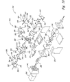
- Figure 9 is an isometric view of the twister assembly 300 of the wire-tying machine 100 of Figure 1 .
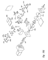
- Figure 10 is an exploded isometric view of the twister assembly 300 of Figure 9 .
- Figure 11 is an enlarged isometric partial view of a gripper subassembly 320 of the twister assembly 300 of Figure 9 .
- Figures 12 through 18 are various cross-sectional views of the twister assembly 300 of Figure 9 .
- Figure 19 is a partial isometric view of a knot 118 produced by the twister assembly 300 of Figure 9 .
- the twister assembly 300 includes a guiding subassembly 310, a gripping subassembly 320, a twisting subassembly 330, a shearing subassembly 350, and an ejecting subassembly 370.
- the guiding subassembly 310 includes a twister inlet 302 that receives the length of wire 102 fed from the feed and tension assembly 200.
- a pair of front guide blocks 303 are positioned proximate the twister inlet 302 and are coupled to a pair of front guide carriers 312.
- a pair of rear guide pins 305 and a pair of front guide pins 306 are secured to a head cover 308 at the top of the twister assembly 300.
- a pair of rear guide blocks 304 are positioned near the head cover 308 opposite from the front guide blocks 303, and are coupled to a pair of rear guide carriers 314.
- a diverter stop block 307 is secured to the head cover 308 proximate the rear guide pins 305.
- a pair of guide covers 309 are positioned adjacent the head cover 308 and together form the bottom of the bundling station 106 ( Figures 1-3 ).
- a guide cam 316 is mounted on a twister shaft 339 and engages a guide cam follower 318 coupled to one of the rear guide carriers 314.
- one of the front guide carriers 312 is pivotably coupled to a guide shaft 319, and the front guide carriers 312 are positioned to pivot simultaneously.
- the guide cam 316 and guide cam follower 318 actuate the rear guide carriers 314.
- the front guide carrier 312 is rigidly connected to the rear carrier 314 by the guide cover 309 such that the guide cam 316 operates both front and rear carriers 312, 314 simultaneously.
- the gripping subassembly 320 includes a gripper block 322 having a gripper release lever 324 pivotally attached thereto.
- the gripper block 322 also has a wire receptacle 321 disposed therein, and a gripper opposite wall 333 adjacent the wire receptacle 321.
- a tapered wall 323 projects from the gripper block 322 proximate to the wire receptacle 321, forming a tapered gap 325 therebetween.
- a gripper disc 326 is constrained to move within the tapered gap 325 by the gripper release lever 324.
- a gripper return spring 328 is coupled to the gripper release lever 324.
- a pair of multi-purpose cams 360, 361 are mounted on the twister shaft 339.
- One of the multi-purpose cams 360 indirectly activates a gripper cam follower 331 through a gripper release rocker 327.
- the gripper release rocker 322 in turn engages a gripper release cam block 335 which, in turn, engages the gripper release lever 324.
- a feed stop switch 337 ( Figure 10 ) is positioned proximate the gripper release lever 324 to detect the movement thereof.
- the twisting subassembly 330 includes a slotted pinion 332 driven by a pair of idler gears 334. As best seen in Figure 18 , the idler gears 334 engage a driven gear 336 which in turn engages a drive gear 338 mounted on the twister shaft 339.
- the cutting subassembly 350 includes a moveable cutter carrier 352 having a first cutter insert 354 attached thereto proximate the twister inlet 302.
- a stationary cutter carrier 356 is positioned proximate the moveable cutter carrier 352.
- a second cutter insert 358 is attached to the stationary cutter carrier 356 and is aligned with the first cutter insert 354.
- One of the multi-purpose cams 360 mounted on the twister shaft 339 engages a cutter cam follower 359 attached to the moveable cutter carrier 352.
- the ejecting subassembly 370 includes a front ejector 372 pivotally positioned near the front guide blocks 303, and a second ejector 374 pivotally positioned near the rear guide blocks 304.
- An ejector cross support 376 ( Figure 10 ) is coupled between the front and rear ejectors 372, 374, causing the front and rear ejectors 372, 374 to move together as a unit.
- An ejector cam 378 is mounted on the twister shaft 339 and engages an ejector cam follower 379 coupled to the front ejector 372.
- a home switch 377 is position proximate the ejector cam 378 for detecting the position thereof.
- the twister assembly 300 performs several functions, including gripping the free end 108 of the length of wire 102, twisting the knot 118, shearing the closed wire loop 116 from the wire source 104, and ejecting the twisted knot 118 while providing a clear path for the passage of the wire 102 through the twister assembly 300. As described more fully below, these functions are performed by a single unit having several innovative features, an internal passive gripper capability, replaceable cutters, and actuation of all functions by a single rotation of the main shaft 339.
- the free end 108 of the length of wire 102 is fed by the feed and tension assembly 200 through the twister inlet 302 of the twister assembly 300.
- the free end 108 passes between the front guide pins 306, and between the front guide blocks 303, and through the slotted pinion 332.
- the free end 108 continues along the wire feed path 202, passing between the rear guide blocks 304, between the rear guide pins 305, and through the wire receptacle 321 in the gripper block 322 ( Figure 11 ).
- the free end 108 then exits from the twister assembly 300 to travel around the track assembly 400 along the wire guide path 402, as shown in Figure 13 , described more fully below.
- the free end 108 After passing around the track assembly 400, the free end 108 reenters the twister inlet 302 (as the upper wire shown in Figures 11 , 11A and 11B ) above the first passage of wire 102a ( Figure 11 ).
- the free end 108 again passes between the front guide pins 306, between the front guide blocks 303, through the slotted pinion 332, and between the rear guide blocks 304 and rear guide pins 305.
- the free end 108 then reenters the wire receptacle 321 and passes above the first passage of wire 102a, past the gripper disc 326 and stops upon impact with the diverter stop block 307.
- the feed cycle is then complete.
- a dot-dashed line is shown in Figures 11 , 11A and 11B to show schematically the completion of the loop of wire around the track.
- the now free end 108 is above the lower wire pass 102a and has been stopped in the twister.
- the lower wire pass 102a remains connected to the accumulator to be pulled back and tighten the wire around the bundle in the track.
- the twister assembly 300 advantageously provides a feed path having a second passage of wire 102b (the free end 108) positioned over a first passage of wire 102a (that goes to the accumulator).
- This over/under wire arrangement reduces wear on the components of the twister assembly 300, especially the head cover 308, during feeding and tensioning. Because the length of wire 102 is pushed or pulled across itself instead of being drawn across the inside of the head cover 308 or other component, wear of the twister assembly 300 is greatly reduced, particularly for the tension cycle.
- the free end 108 (or the upper passage of wire 102b) of the length of wire 102 is aligned adjacent to the gripper disc 326.
- the gripper disc 326 ( Figure 11 ) is constrained to move within the gap 325 by the gripper release lever 324, the tapered wall 323, and the back wall; both walls being within the gripper block 322:
- the second passage of wire 102b begins to move in the tension direction (arrow 134) and frictionally engages the gripper disc 326, moving the gripper disc 326 in the tension direction and forcing the gripper disc 326 into increasingly tight engagement between the wire's free end 102b and the tapered wall 323.
- the gripper release lever is pivotally mounted on an offset pivot pin 343 so that the friction force between the wire and the disc 326 create an increasing moment pivoting the lever counter clockwise and closer to the opposite wall 333.
- the gripper disk 326 may be constructed from a variety of materials, including, for example, tempered tool steel and carbide, a fairly hard material is preferred to withstand repeated cycling.
- FIGs 11A and 11B show alternative embodiments of the gripper release lever 324.
- the gripper disc 326 is rotatably fixed in the gripper release lever 324a.
- the gripper release lever 324a is pivoted on pivot pin 343 such that movement of the wire pass 102b to the left as viewed in Figure 11A will cause the disc 324 to frictionally engage the wire, causing the gripper release lever 324a to pivot counter clockwise about the pin pivot 343, pressing the disc 326 against the wire 102b.
- the wire becomes squeezed between the disc 326 and the opposite wall 333.
- All of these embodiments uniquely accomplish gripping of the free end of the wire with a passive gripper that requires no separate powered solenoids or actuators.
- the gripper release lever is biased by spring 328 to normally pivot counter clockwise. The friction then between the wire, the wall, and the gripper disc provides the holding power.
- the magnitude of the imparted force wedging the disc 326 into the narrow end of the tapered gap 325 is reduced and the direction with which the wire end 108 engages the gripper disc 326 is altered. This allows the wire end 108 to slip transversally up from between the disc 326 and the wall 333.
- the cam block 335 is engaged by the gripper release cam follower 331 at the end of the twist cycle forcing the gripper release lever 324 to rotate in a clockwise direction, as viewed in Figures 12 and 12A , disengaging contact between the gripper disc 326 and the wire end 108.
- This also opens an unobstructed path for the wire to clear the gripper subassembly 320 at the time of wire ejection.
- the twisting subassembly 330 twists a knot 118 in the wire 102 to close and secure the wire loop 116.
- the twisting is accomplished by rotating the slotted pinion 332.
- the twister motor 340 rotates the twister shaft 339, causing the drive gear 338 to rotate.
- the drive gear 338 in turn drives the driven gear 336.
- the two idler gears 334 are driven by the driven gear 336 and, in turn, drive the slotted pinion 332.
- the rotation of the slotted pinion 332 twists the first and second passages of wire 102a, 102b forming the knot 118 shown in Figure 19 .
- the wire 102 is severed to release the formed loop 116.
- the motion of the multi-purpose cams 360, 361 against the cutter cam followers 359, 362 actuates the movable cutter carrier 352 ( Figure 13 ) relative to the stationary cutter carrier 356, causing the wire 102 to be sheared between the first and second cutters 354, 358.
- the first and second cutters 354, 358 are replaceable inserts of the type commonly used in commercial milling and cutting machinery, although other types of cutters may be used.
- the twister assembly 300 advantageously provides symmetrical loading on the pinion 332 by the two idler gears 334.
- This double drive arrangement produces less stress within the pinion 332, the strength of which is reduced by the slot.
- the pinion 332 is slotted between gear teeth, which allows complete intermeshing with the idler gears 334. This configuration also results in less stress in the pinion 332.
- an alternate pinion embodiment having a tooth removed may be used to provide clearance for the wire during ejection, as described below.
- the tension in the wire 102 restrained by the gripping subassembly 320 is reduced.
- the rotation of the multi-purpose cams 360, 361 actuates the cutter cam followers 359-362, causing the head cover 308 and guide covers 309 to open.
- the rotation of the ejector cam 378 actuates the ejector cam follower 379, causing the front and rear ejectors 372, 374 to raise.
- the rotation of the multi-purpose cams 360-361 also causes the gripper cam follower 331 to engage the gripper release cam block 335, pivoting the gripper release lever 324 and forcing the gripper disc 326 away from the wire 102. This allows the free end 108 to freely escape from the twister assembly 300.
- the front and rear ejectors 372, 374 push the wire 102 and the knot 118 out of the pinion 332, lifting the wire loop 116 free from the twister assembly 300.
- a modified form of twister assembly 300a is shown in Figures 9A , 10A , 12A and 13A .
- a movable head cover 308a abuts a fixed hard cover.
- the moveable head cover is attached to a pair of rocker arms 327a and 352a that pivot on pins 800.
- a pair of cam followers 362a and 359a ( Figure 13A ) pivot the rocker arms in response to head opening cams 360a and 361a mounted on the main twister shaft 339. This opens the movable head cover away from the fixed head cover to release the wire.
- the twister assembly 300 advantageously performs the guiding, gripping, twisting, shearing, and ejecting functions in a relatively simple and efficient cam-actuated system.
- the simplicity of the above-described cam-actuated twister assembly 300 reduces the initial cost of the wire-tying machine 100, and the maintenance costs associated with the twister assembly 300.
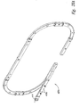
- Figure 20 is an exploded isometric view of the track assembly 400 of the wire-tying machine 100 of Figure 1 .
- the track assembly 400 includes a feed tube subassembly 410, a track entry subassembly 420, and alternating straight sections 430 and corner sections 450.
- the feed tube assembly 410 includes a ring sensor 412 coupled to a non-metallic tube 414.
- a feed tube coupling 416 couples a main feed tube 418 to the non-metallic tube 414.
- the main feed tube 418 is, in turn, coupled to the track entry subassembly 420.
- the track entry subassembly 420 includes a track entry bottom 422 coupled to a track entry top 424 and a track entry back 426.
- a groove 423 is formed in a lower surface of the track entry top 424.
- the track entry back 426 is coupled to the track entry bottom and top 422, 424 by a pair of entry studs 425 and is held in compression against the track entry bottom and top 422, 424 by a pair of entry springs 427 installed over the entry studs 425.
- a first wire slot 428 and a second wire slot 429 are formed in the track entry back 426.
- the track entry subassembly 420 is coupled between the feed tube 418, a track corner 452, 456, and the twister assembly 300.
- the straight section 430 of the track is constructed to guide the wire but to release the wire when tension is applied to the wire.
- each corner section 450 includes a corner front plate 452 and a corner back plate 454.
- the corner front and back plates 452, 454 are held together by fasteners 436 along their respective spine sections 437.
- a plurality of identical ceramic segments 456 are attached to each corner back plate 454 and are disposed between the corner front and back plates 452, 454.
- the ceramic sections 456 each include a rounded face 458 that partially surrounds the wire guide path 402.
- the free end 108 of the length of wire 102 is fed by the feed and tension assembly 200 through the non-metallic tube 414 about which the ring sensor 412 is located.
- the ring sensor 412 detects the internal presence of the wire 102 and transmits a detection signal 413 to the control system 500.
- the free end 108 then passes through the feed tube coupling 416, the main feed tube 418 and into the track entry subassembly 420.
- the free end 108 initially passes from the main feed tube 418 into the groove 423 cut into the track entry top 424, which is secured to the track entry bottom 422.
- the free end 108 passes through the groove 423 into and through the first wire slot 428 in the track entry back 426, through the twister assembly 300, and into the first straight section 430 of the track assembly 400.
- track entry sub-assembly 420a substitutes conventional straight opening track sections 418a for the main feed tube 118.
- This opening track section allows for removal of excess wire from the accumulator drum by opening the twister head and then feeding the wire against the cutter. This causes the wire to bubble out of the track sections 418a while controlling both ends of the wire which are to be removed from the machine.
- the straight sections 430 maintain the direction of the free end 108 along the wire guide path 402.
- the straight front and back plates 432, 434 are releasably held together along their respective spine sections 437.
- the structure allows the sections to separate in a manner to free the wire when tensioned.
- the free end 108 is fed into the corner section 450.
- the ceramic sections 456 change the direction of the free end 108 of the length of wire 102, while preferably imposing minimal friction.
- the ceramic sections 456 are relatively impervious to gouging by the sharp, rapidly moving free end 108.
- the ceramic sections 456 may be fabricated from a variety of suitable, commercially-available materials, including, for example, pressure formed and fired A94 ceramic. It is understood that the plurality of ceramic sections 456 contained within each corner section 450 may be replaced with a single, large ceramic section.
- the structure of the corner sections 450 provides for the containment of the wire 102 during the feed cycle by the natural elasticity of the corner front and back plates 452, 454, while allowing the wire 102 to escape from the corner section 450 during the tension cycle. Because the rounded face 458 only partially surrounds the wire guide path 402, the wire 102 may escape from between the corner front and back plates 452, 454 during tensioning.
- the track assembly 400 need not have a plurality of alternating straight and corner sections 430, 450.
- the track assembly 400 having the alternating straight and corner sections 430, 450 affords a modular construction that may be easily modified to accommodate varying sizes of bundles.
- Figure 22 shows segments 456a as hardened tool steel with a rounded face 458a. These steel segments are also tapered from entry end to exit end into a funnel shape to guide the wire concentrically into the next abutting segment.
- the free end 108 continues to be fed into and through alternating straight and corner sections 430, 450 until it is fed completely around the track assembly 400.
- the free end 108 then enters the track entry subassembly 420, passing into the second wire slot 429 in the track entry back 426.
- the free end 108 then reenters the twister assembly 300 and is held by the gripping subassembly 320 as described above.
- the track entry back 426 is disengaged from the track entry top 424 by compression of the entry springs 427 as the wire 102 is drawn upwardly between the track entry back and top 426, 424, releasing the second passage of the wire 102 from the track entry subassembly 420 and allowing the wire 102 to be drawn tightly about the one or more objects located in the bundling station 106.
- the twister assembly 300 performs the twisting, cutting, and ejecting functions, the wire loop 116 is free of the track assembly 400.
- FIG. 23 is a schematic diagram of the control system 500 of the wire-tying machine 100 of Figure 1 .
- Figure 24 is a graphical representation of a cam control timing diagram of the twister assembly 300 of Figure 9 .
- Figure 25 is a graphical representation of a twister motor control timing diagram of the twister assembly 300 of Figure 9 .
- the control system 500 includes a controller 502 having a control program 503 and being operatively coupled to a non-volatile flash memory 504, and also to a RAM memory 506.
- the RAM 506 may be re-programmed, allowing the control system 500 to be modified to meet the requirements of varying wire-tying applications without the need to change components.
- the non-volatile flash memory 504 stores various software routines and operating data that are not changed from application to application.
- the controller 502 transmits control signals to the drive and twister control modules 510, 514, which in turn transmit control signals to the drive and twister assemblies 200, 300, particularly to the drive and twister motors 242, 340.
- a variety of commercially available processors may be used for the controller 502.
- the controller 502 is a model 80C196NP manufactured by Intel Corporation of Santa Clara, California; and having features: a) 25 Mhz operation, b)1000 bytes of RAM register, c) register-register architecture, d) 32 I/O port pins, e) 16 prioritized interrupt sources, f) 4 external interrupt pins and NMI pins, g) 2 flexible 16-bit timer/counters with quadrature counting capability, h) 3 pulse-width modulator (PWM) outputs with high drive capability, i) full-duplex serial port with dedicated baud rate generator, j) peripheral transaction server (PTS), and k) an event processor array (EPA) with 4 high-speed capture/compare channels.
- PWM pulse-width modulator
- Analog feedback signals may also be used, allowing the controller 502 to use a variety of analog sensors, such as photoelectric or ultrasonic measuring devices.
- the control program 503 determines, for example, the number of rotations, the acceleration rate, and the velocity of the motors 242, 340, and the controller 502 computes trapezoidal motion profiles and sends appropriate control signals to the drive and twister control modules 510, 514.
- the control modules 510, 514 provide the desired timing control signals to drive the twister assemblies 200, 300, as shown in figures 24 , 25 .
- controllers 510 and 514 A variety of commercially available processors may be used for controllers 510 and 514.
- the controllers 510, 514 are model LM628 manufactured by National Semiconductor Corporation of Santa Clara, California.
- the controller 502 may also receive motor position feedback signals from, for example, motor mounted encoders. The controller 502 may then compare positions of the drive motor 242 and the twister motor 340 with desired positions, and may update the control signals appropriately.
- the controller 502 may update the control signals at rate of 3000 times per second.
- the feedback signals are digital signals, the feedback signals are conditioned and optically isolated from the controller 502. Optical isolation limits voltage spikes and electrical noise which commonly occur in industrial environments. Analog feedback signals may also be used, allowing the controller 502 to use a variety of analog sensors, such as photoelectric or ultrasonic measuring devices.
- the watchdog timer 520 of the supervisory module 518 interrupts the controller 502 if the controller 502 does not periodically poll the watchdog timer 520.
- the watchdog timer 520 will reset controller 502 if there is a program or controller failure.
- the power failure detector 522 detects a power failure and prompts the controller 502 to perform an orderly shutdown of the wire-tying machine 100.
- the load cycle is used to thread (or re-thread) the length of wire 102 into the wire tying machine 100 from the wire supply 104.
- the load cycle is utilized when the wire supply 104 has been exhausted, or when a fold or break necessitates reinsertion of the wire 102 into the machine 100.
- the feed solenoid 265 is actuated.
- the wire 102 is then manually fed into the wire tying machine 100 from the remote wire supply 104, through the wire inlet 225 ( Figure 3 ).
- the wire 102 is then manually forced through the hollow center of the accumulator axle 224, around the transverse guide wheel 234 (or through the curved roller axle tube 235) and around the tangent guide wheel 236.
- the wire 102 is forced into the pinch area between the tangent guide wheel 236 and tangent pinch roller 239.
- the drive motor 242 having been actuated by the insertion of wire 102, turns the drive wheel 246 at slow speed in the feed direction 132.
- the wire 102 is deflected around the tangent guide wheel 236 and between the tangent guide wheel 236 and a drive wheel 246.
- the feed pawl 267 having been forced down by the feed solenoid 265 deflects the free end 108 of the wire 102 around the drive wheel 246.
- the load cycle is halted when the wire 102 is detected at the ring sensor 412, or by deactivation of the manual feed.
- Initiation of the feed cycle engages the drive wheel 246 to feed the length of wire 102 through the twister assembly 300 and around the track assembly 400.
- the drive motor 242 rotates the drive shaft 248 and drive wheel 246 through the 90° gear box 244.
- the wire 102 is fed across the drive wheel 246 adjacent to the drive entry guide 260, under the drive pinch roller 249, and adjacent to the drive exit guide 262 where the exhaust pawl 266 is located.
- the wire 102 is then fed through the feed tube subassembly 410, through the twister assembly 300, around the track assembly 400, and back into the twister assembly 300 to be restrained by the gripping subassembly 320.
- the feed stop switch 337 detects the movement of the gripper disc 326 associated with the presence of the wire 102 and signals the location of the wire 102 to the control system 500 to complete the feed cycle.
- the slow speed feed continues until the free end 108 energizes the feed stop switch 337 indicating the completion of the feed cycle. If the control system 500 detects that a sufficient length of wire 102 has been fed without triggering the feed stop switch 337 (i.e., a wire misfeed has occurred), the control system 500 halts operation and issues an appropriate error message, such as illuminating a warning light.
- the tension cycle is initiated, either manually or by the control system 500, causing the drive motor 242 to rotate the drive wheel 246 in the tension direction 134, withdrawing the wire 102 partially from the track assembly 400.
- the drive motor 242 ramps to high-speed in the tension (accumulate) direction 134. The number of rotations of the drive motor 242 may be counted for reference during the following feed cycle.
- the high-speed phase is terminated when a minimum loop size has been reached or when the drive motor 242 stalls. If the minimum loop size is encountered the machine will be directed to do one of two possible things depending upon desired machine operation. Either the control system 500 halts operation, or the machine continues as normal by initiation of the twist cycle, thus clearing the empty wire loop from the machine for continued operation.
- Tension on the wire causes the gripper disc 326 to impinge upon the second passage of the wire 102b, passively increasing its gripping power with increased wire tension.
- the wire 102 is thus pulled from the wire guide path 402 and is drawn about the one or more objects within the bundling station 106.
- the drive wheel 246 is located adjacent to the tangent guide wheel 236. Because the tangent guide wheel 236 is mounted on a clutch 238 that operates freely in only one direction, the tangent guide wheel 236 is unable to rotate relative to the accumulator drum 222 into tension direction 134.
- the entire accumulator drum 222 rotates in response to the impetus from the drive wheel 246, smoothly laying the wire along the helical groove 229 in the accumulator drum 222.
- the accumulator drum 222 is forced to move laterally along its axis of rotation between the supports 230 by the wire laying into the groove as the wire proceeds along the helical groove 229.
- Wire is wound around the accumulator drum 222 until the drive motor 242 stalls, at which time the drive motor 242 is given a halt command by the control system 500.
- the halt command causes the drive motor 242 to maintain its position at the time the command was given, thus maintaining tension in the wire 102.
- the control system 500 may record the amount of wire stored on the accumulator drum 222 by means of a signal from an encoder on the drive motor 242, which may be used during the subsequent feed cycle to determine a feed transition point, that is, a point at which feeding is transitioned from feeding wire stored on the accumulator drum 222 to feeding from the external wire supply 104.
- the drive motor 242 maintains the tension in the wire 102 by maintaining its position at the time when the halt command was given by the control system 500.
- the drive motor stall also initiates the twist cycle in the automatic mode, as described below. After the wire 102 has been severed during the overlapping twist cycle, the tension in the wire 102 may cause the wire to retract a short distance after it is abruptly released. The tension cycle is terminated at the completion of the twist cycle (described below) and the drive motor 242 ceases operation until the start of the next feed cycle.
- the twist cycle is initiated.
- the head cover 308 opens to allow space for formation of the knot 118.
- the twister motor 340 applies torque to the twister shaft 339 through the gear reducer 342, rotating the drive gear 338 and ultimately the slotted pinion 332.
- the guide cam 316 engages the guide cam follower 318, opening the front and rear guide blocks 303, 304 to allow clearance for the knot 118 to be formed.
- the wire 102 is forced by the rotating pinion 332 to wrap about itself, typically between two and one-half and four times, creating the knot 118 which secures to be wire loop 116.
- the movable cutter carrier 352 is actuated to sever the wire 102, and the front and rear ejectors 372, 374 are raised, as the head opens, ejecting the wire loop 116 from the twister assembly 300.
- the total twist cycle is produced by one complete revolution of the twister shaft 339, which is typically a result of several revolutions of the twister motor 340 whose number varies depending upon the gear ratio used in the gear reducer 342.
- the home switch 377 detects the position of the ejector cam 378 and signals the control system 500 that a complete revolution has occurred.
- the control system 500 reduces the speed of the twister motor 340 to slow, and a homing adjustment is made ( Figure 25 ).
- the control system 500 may also halt the rotation of the twister motor 340 if an excessive number of rotations of the twister motor 340 is detected. If this occurs, the twister motor 340 is halted with enough clearance to allow the release of the wire 102 or wire loop 116. The control system 500 may then generate an appropriate error message to the operator, such as illuminating a warning lamp. If the twister motor 340 has not faulted, the control system makes a homing adjustment and the twister motor 340 is dormant until required for the next twist cycle.
- the wire reject cycle is used to clear any accumulated wire in the event that all wire must be removed from the wire tying machine 100.
- the wire reject cycle typically operates in the manual mode.
- the wire reject cycle is initiated by to energizing the drive motor 242, rotating the drive wheel 246 at slow speed in the tension direction 134. Wire fed into the track assembly 400 and the twister assembly 300 is withdrawn and stored about the accumulator drum 222 until the free end 108 is inboard of the exhaust pawl 266. Then the exhaust solenoid 264 is energized to deflect the exhaust pawl 266, and a drive wheel 246 rotation is re-energized in the feed direction 132.
- the drive wheel 246 continues to run slowly in the feed direction 132 until the manual feed command is released and as long as the wire 102 remains in the machine 100.
- the wire 102 is exhausted slowly out of the machine 100 along the wire exhaust path 204 ( Figure 8 ) and onto the floor were it may be easily removed.
- the control system 500 advantageously allows important control functions to be programmably controlled and varied.
- Conventional wire-tying machines utilized control systems which were designed to apply a particular force for a set period of time.
- the control system 500 of the wire-tying machine 100 permits the machine to adapt its performance and specifications to yet undefined requirements. Due to this flexibility, great cost savings may be realized as wire-tying requirements are varied from application to application.
- the wire tying machine 100 is fully electric without using hydraulic or pneumatic systems traditionally used in wire-tying apparatus. Elimination of hydraulics reduces the physical dimensions of the machine 100, eliminates the impact of hydraulic fluid spills and the need for hydraulic fluid storage, reduces maintenance requirements by eliminating hydraulic fluid filters and hoses, and reduces mechanical complexity. Also, because electric servo-motors are motion-based systems, as opposed to hydraulic systems that are forced or power-based systems, inherent flexibility in motion control is provided without the need for additional control mechanisms or feedback loops. Another advantage is that the power consumption of a servo-motor system is much less than that of a hydraulic system.
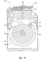
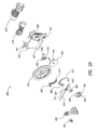
- FIG. 26-28 An alternative embodiment of the feed and tension mechanism 600 is illustrated in Figures 26-28 . To avoid confusion, the structural elements of the mechanism are identified with reference numbers in Figures 27 and 28 , and the arrows illustrating operational nodes are independently illustrated in Figures 38-40 .
- the feed and tension mechanism 600 has several major assemblies, including a feed and tension wheel, 645, an accumulator wheel 641, a drive system comprising two independently operable motors, a supplementary nip mechanism 643, a primary nip mechanism 661, a wire stripping mechanism 800, and a series of wire sensing devices in communication with a control system. At least some of the aforementioned assemblies also include wire guiding devices for directing and routing the wire through the feed and tension mechanism 600.
- the feed and tension mechanism 600 further includes a frame 671 that structurally supports the major assemblies and attaches to the wire-tying machine 100.
- a feed and tension unit frame 671 provides the attachment points for a feed wheel gearmotor 673, an accumulator gearmotor 675, an accumulator wheel 641, a feed and tension wheel 645, and the upper and lower nip wheels 643, 661.
- a lower flange 677 of the frame 671 can provide the attachment point to the wire-tying machine 100 through standard mechanical means such as bolts.
- the feed and tension wheel 645 may be mounted on feed wheel shaft 683 attached to the frame 671.
- the feed and tension wheel 645 can be proximately located to the accumulator wheel 641, but not in physical contact.
- the feed and tension wheel 645 is configured with a feed wheel wire groove 649.
- the accumulator wheel 641 may be mounted on an accumulator wheel shaft 679 attached to the frame 671.
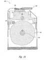
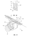
- Figure 29 is an exploded isometric view of the accumulator wheel 641.
- the accumulator wheel 641 is comprised of several hollow, circular plates and an accumulator hub 639.
- the accumulator hub 639 can be coupled to the accumulator wheel shaft 679 which may be mounted to the frame 671 with bearings and a bearing block.
- the remaining components include a spacer 635 sandwiched between inner 637 and outer 633 circular wear plates.
- the three components can be fastened to the accumulator hub 639 ( Figure 29 ).
- Section 30-30 of Figure 28 an upper portion of the accumulator wheel 641, is shown as Figure 30 .
- the spacer 635 has a smaller outer diameter relative to the inner 637 and outer 633 wear plates, such that an accumulator groove 627 is formed to receive accumulated wire.
- the width 631 of the accumulator groove 627 is at least equal to the wire diameter while the depth 629 of the accumulator groove can be deep enough to permit several wraps of wire to be completely captured within the accumulator groove 627.
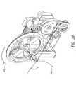
- the next major assembly of the feed and tension mechanism 600 is the drive system, best seen in Figure 28 .
- the drive system includes two independent motors, an accumulator gearmotor 675 and a feed wheel gearmotor 673.
- the accumulator gearmotor 675 is located on the opposite side of the frame 671 relative to the accumulator wheel 641.
- the feed wheel gearmotor 673 is located on the opposite side of frame 671 relative to the feed and tension wheel 645.
- the accumulator gearmotor 675 drives the rotational movement of the accumulator wheel 641 in an accumulator tension direction "AT” and in an opposing accumulator feed direction.
- the feed wheel gearmotor 673 drives the rotational movement of the feed and tension wheel 645 in both a feed wheel feed direction "FF" and a feed wheel tension direction "FT.”
- Both the accumulator and feed wheel gearmotors, 675 and 673, can be operated by the control system 500.
- the control system 500 may utilize closed loop flux vector drive technology or other methods of control as the means of operating and controlling the respective gearmotors.
- the supplementary nip mechanism 643 can facilitate the manual insertion of the wire into the feed and tension mechanism 600.
- the supplementary nip mechanism 643 is rotatably attached to the frame 671 and may be located above the feed and tension wheel 645.
- the supplementary nip mechanism 643 may be configured with a movable eccentric 651 attached to a lever arm 653.
- the lever arm 653 may be actuated by a linear actuator 655, such as a solenoid. Energizing of the solenoid 655 moves the lever arm 653 and the eccentric 651 to create contact between the supplementary nip mechanism 643 and the feed and tension wheel 645.
- the supplementary contact region 657 ( Figure 38 ) between the supplementary nip mechanism 643 and the feed and tension wheel 645 is the point where the wire becomes frictionally guided by the pinching force of the supplementary nip mechanism 643 impinging against the feed and tension wheel 645.
- the next major assembly which may be located near the bottom portion of the feed and tension wheel 645 as seen in Figure 27 , is the primary nip mechanism 661.
- the illustrated primary nip mechanism 661 is rotatably and eccentrically affixed to the frame 671.
- the primary nip mechanism 661 is comprised of a primary nip wheel 663 eccentrically mounted to the primary nip wheel lever arm 665. Motion of the primary nip wheel lever arm 665 causes the primary nip wheel 663 to eccentrically rotate relative to the primary nip mechanism mounting shaft 681 extending out from the frame 671.
- the primary nip wheel lever arm 665 may be spring 667 actuated as shown in Figure 38 .
- the purpose of the primary nip mechanism 661 is to apply a pinch force between the primary nip wheel 663 and the feed and tension wheel 645.
- the nip force at the primary nip contact region 669 can override the frictional engagement at the supplementary contact region 657 and can take primary control of drawing the wire into the feed and tension mechanism 600.
- the default position of the primary nip mechanism 661 can be in biased contact with the feed and tension wheel 645.
- Figure 40 provides a cutaway view of the wire stripping mechanism 800 showing the extraction path 823 of the wire. Stripping of the wire from the feed and tension mechanism 600 may occur when the wire has not been completely fed around the track assembly 400 ( i.e., a misfeed) or when the external wire supply has become depleted and the trailing end of the wire 703 enters the feed and tension mechanism 600.
- Figure 40 illustrates the path of the leading end of wire coming from the feed and tension wheel 645. During stripping, the path is interrupted by the wire strip gate 805.
- the wire stripping mechanism 800 can be comprised of several components such as the wire strip gate 805, a lever arm 811, a pivot pin 809, a mounting plate 815, and a gate deflection device 813.
- the wire strip gate 805 can be have a first end 817 configured to have a narrow, knife-edged portion and a second end 819 configured with a squared, boxed, flanged, rounded, or rectangular shape. Located between the first end 817 and second end 819 of the wire strip gate 805 can be a pivot slot 821.
- the wire strip gate 805 may be made from a flat stock of material such as metallic, composite, or plastic with the thickness being approximately equal to or slightly greater than the diameter of the wire. Additionally, the wire strip gate 805 can be configured to have a longitudinal slot (not shown) for more accurately directing the wire into the wire coiler 803.
- the wire strip gate 805 can be insertable into the wire gate slot 823 of the feed exit guide 613 ( Figure 35 ).
- the lever arm 811 can have a deflection end 829 and a pivot end 825.
- the deflection end 829 can be received into a plunger slot 827 on the gate deflection device 813.
- the deflection end 829 of the lever arm 811 and the plunger 831 may be mechanically fastened to prevent any relative motion ( Figures 33-35 ).
- Figures 33-35 illustrate the attachment of the wire strip gate 805 and the lever arm 811 which are connected by the pivot pin 809.
- One portion of the pivot pin 809 can be clamped into the pivot end 825 of the lever arm 811.
- Another portion of the pivot pin 809 can be press fit into the pivot slot 821 of the wire strip gate 805.
- any rotation of the lever arm 811 would cause the pivot pin 809 and the wire strip gate 805 to also rotate accordingly.
- the pivot pin 809 can be inserted through attachment blocks 807 and freely rotatable therein.
- the blocks 807 can be mechanically mounted to the feed exit guide 613 as depicted in Figure 32 .
- the wire strip gate 805, being rotatably affixed to the lever arm 811 through the pivot pin 809, can be configured such that first end 817 of the wire strip gate 805 can be deflected into and out of the wire gate slot 823 by the gate deflection device 813.
- the gate deflection device 813 can be a stripper solenoid 833 with a slotted plunger 831.
- the slotted plunger 831 can have a lever arm attach slot 827 wherein the deflection end 829 of the lever arm 811 can be inserted.
- actuation of the stripper solenoid 833 causes the first end 817 of the wire strip gate 805 to either block or clear the wire path within the feed exit guide 613.
- the stripper solenoid 833 can be energized to cause the slotted plunger 831 to pull on the lever arm 811, thereby rotating the wire gate first end 817 into the path of the wire to reroute the leading end of the wire 701 into the wire coiler as shown schematically in Figure 37 .
- the wire strip gate 805 in the non-stripping mode is shown in Figure 36 , the stripper solenoid non-energized, where the leading end of the wire 701 bypasses the wire strip gate 805 in the feed direction "F" to the track assembly 400.
- the mounting plate 815 permits the attachment of the gate deflection device 813 and the wire coiler 803 to the feed exit guide 613. As illustrated in Figure 34 , the mounting plate 815 captures the wire strip gate 805 within the wire path.
- the mounting plate 815 can be configured with a release slot 835 to permit the attachment of the slotted plunger 831 with the second end 819 of the wire strip gate 805 and to allow the wire strip gate 805 to freely rotate within the wire gate slot 823 ( Figures 34 and 35 ).
- a wire coiler 803 for accepting the extracted wire can be connected adjacent to the feed exit guide 613 with a mounting plate 815.
- the wire coiler 803 may be cylinder-shaped with an internal helical groove. It is possible to either partially or fully encompass the helical groove to restrain the leading end of the wire 701 as it exits from the wire strip gate 805.
- the helical groove of the wire coiler 803 forms the extracted wire into a manageable coil as it is driven from the feed and tension mechanism 600 so the waste wire can be easily removed by the operator.
- the wire sensing devices such as the wire present switch 601 and the feed tube switch 615 are comprised of a loop proximity sensor that detects metal.
- the respective switches include a ceramic tube passing through the center of the sensor that guides the wire and protects the sensor.
- the wire guiding devices are instrumental in directing and routing the wire during each operational cycle, especially the threading of the machine.
- the wire guiding devices include an adjustable entry guide 601, an axial-to-radial guide 605 mounted on the accumulator shaft 679 proximately located to the accumulator wheel 641, a radial-to-tangential guide 607 mounted on the accumulator wheel 645 and distally located from the accumulator shaft 679, a transfer guide 609 located between the accumulator wheel 641 and feed and tension wheel 645 and can be mounted on the frame 671, a feed wheel guide 611 which may be attachable to the frame 671 and circumferentially directs the wire around the feed wheel 645, a feed exit guide 613 located downstream of the feed wheel guide 611 for directing the wire tangentially away from the feed wheel 645, and finally a feed tube 615 attached to the feed exit guide 613 for project
- the feed and tension mechanism 600 can perform at least four operations, initial threading of wire into a wire-tying machine 100, tensioning and accumulating wire during bundling of one or more objects, subsequent threading and feeding of wire into a track assembly 400 after an initial tensioning operation, and stripping wire from the mechanism in the event of a system jam or an out of wire signal.
- the first operation is to initially thread the wire into an empty feed and tension mechanism 600. Threading of the feed and tension mechanism 600, shown schematically in Figure 38 , commences with a leading end of a wire 701 being manually inserted into an adjustable entry guide 601 and pushed past the "wire present" switch 603.
- the adjustable entry guide 601 is configured to readily receive the leading end of the wire 701 from any location adjacent to the entry side of the machine.
- the illustrated wire present switch 603 is located down stream of the adjustable entry guide 601. The wire present switch 603 detects the presence of the wire 701 and signals the control system 500 to start the feed wheel gearmotor 673.
- a wire present signal is also supplied to the supplementary nip wheel 643 to engage the feed and tension wheel 645, and ultimately the wire, in a feed direction "FF" ( Figure 38 ).
- the wire present switch 603 can continue to provide a wire present indication to the control system 500 as long as wire is located within the perimeter of the switch.
- the leading end of the wire 701 passes the wire present switch 603 and into the wire guiding components attached to the accumulator wheel 641.
- these wire guiding components are the axial-to-radial guide 605 and the radial-to-tangential guide 607 which, working in combination, direct the wire toward the feed and tension wheel 645.
- the leading end of the wire 701 enters the axial-to-radial guide 605 along the centerline of the accumulator disk shaft 679, but does not pass through the accumulator wheel 641.
- the axial-to-radial guide 605 routes the wire from an axial to a radial direction with respect to the accumulator wheel 641; whereas the radial-to-tangential guide 607 receives the leading end of the wire 701 and further directs the wire toward the feed and tension wheel 645.
- the passage of the wire just downstream of the radial-to-tangential guide 607 can be further directed by another wire guiding component, the transfer guide 609, located between the accumulator wheel 641 and the feed and tension wheel 645.
- the transfer guide 609 contains the wire as it exits from the radial-to-tangential guide 607 and it circumferentially directs the leading end of the wire 701 into the feed wheel groove 649.
- the leading end of the wire 701 exits the transfer guide 609, it contacts the supplemental nip mechanism 643.
- the wire becomes drawn into the supplemental contact region 657 ( i.e ., Figure 38 ).
- the contact between the supplemental nip mechanism 643 and the feed and tension wheel 645 causes the entering wire to become frictionally drawn through the contact region 657. From this point forward during the threading operation, the engagement of the supplemental nip mechanism 643 with the feed wheel 645 augments the manually threading of the mechanism 600.
- the wire 701 As the lead end of the wire 701 is frictionally drawn through the supplemental contact region 657, the wire is further directed by another wire guiding component, the feed wheel guide 611.
- the wire having a tendency to straighten upon leaving the supplemental contact region 657 is circumferentially contained by the feed wheel guide 611 as the wire progresses around the feed wheel 645 in the feed direction FF.
- the leading end of the wire encounters the primary contact region 669 created by the primary nip mechanism 661 being biased against the feed wheel 645.
- the purpose of the primary nip mechanism 661 is to apply a pinch force between the primary nip wheel 663 and the feed and tension wheel 645.
- the nip force at the primary nip contact region 669 can override the frictional engagement at the pinch force at the supplemental contact region 657 and can take primary control of feeding the wire.
- the default position of the primary nip mechanism 661 can be in biased contact with the feed and tension wheel 645.
- the leading end of the wire 701 upon being drawn through the primary nip contact region 669, now enters the feed exit guide 613.
- the feed exit guide 613 directs the wire into the feed tube 615.
- the leading end of the wire 701 may be detected by a feed tube switch 617.
- the purpose of the illustrated feed tube switch 617 during the threading operation is to detect the leading end of the wire 701 and to provide the control system 500 with another wire present signal.
- the wire present signal received from the feed tube switch 617 can instruct the control system 500 ( Figure 26 ) to disengage the supplemental nip mechanism 643 by de-energizing the upper nip wheel solenoid 655.
- the primary nip contact region 669 can provide sufficient frictional engagement of the wire such that the supplemental nip contact region 657 is no longer needed and continued contact would only increase heat within the mechanism 600 and cause component wear.
- the feed tube switch 617 can also detect the leading end of a wire 701 in order to reset the twister assembly 300 ( Figure 26 ) to its home position in the event of an error.
- the feed tube 615 directs the wire to an outlet region, such as the track entry subassembly 420, for execution of a bundling operation as discussed in connection with the foregoing embodiment.
- the wire present signal received from the feed tube switch 617 can instruct the control system 500 to transition from threading to feeding and accordingly notify the operator. At this point, the operator will no longer manually feed wire into the feed and tension mechanism 600 and will activate the feed cycle.
- the feed cycle allows the feed wheel gearmotor 673 to increase the speed of the feed wheel 645 in the feed direction "FF" until the wire has been completely routed around the track entry subassembly 420, which completes the initial threading operation.
- the tensioning operation may be commenced.
- One or more objects can be placed in the track assembly 400 to be bundled.
- the feed and tensioning mechanism can be controlled to tension the wire around the objects.
- the tensioning operation is schematically illustrated in Figure 39 .
- Several components within the feed and tension mechanism 600 can work together to effectuate sufficient tensioning of the wire and to accumulate any excess wire during the process. The excess wire is created because the perimeter of the one or more objects being bundled is less than that of the track assembly 400 opening where the wire resides just prior to the tensioning operation.
- the actual tensioning of the wire around the one or more bundled objects requires that the excess wire be drawn from the track assembly 400 ( Figure 39 ) and accumulated on the accumulator wheel 641.
- One purpose of the accumulator wheel 641 is to accumulate and store the excess wire that is tensioned from the track assembly 400 until the wire is needed for another bundle.
- the wire is tensioned (i.e., drawn) back from the track assembly 400.
- the accumulator wheel 641 is driven by the accumulator gearmotor 675 in the accumulator tension direction "AT” ( Figure 39 ).
- the wire drawn from the track assembly by the frictional engagement of the primary nip contact region 669 can be directed to the rotating accumulator wheel 641 into the accumulator groove 627 by the transfer guide 609 during tensioning.
- The(transfer guide(609, being affixed to the frame 671, directs the wire from the feed and tension wheel 645 into the accumulator groove 627.
- the tensioning operation can be halted by presetting the feed wheel gearmotor 673 to stall at a predetermined torque level once the wire is sufficiently tight around the bundle of objects.
- the predetermined torque level may be set by the operator based on the objects to be bundled, the wire diameter, and/or the strength of the wire.
- the control system 500 detects the feed wheel gearmotor 673 stall and holds the motor in position while the wire is twisted, cut and ejected.
- the accumulated wire stored on the accumulator wheel 641 may now be utilized for a subsequent bundling operation and fed into the track assembly 400 after the initial tensioning operation.
- the subsequent bundling operation commences with the accumulator wheel 641 and feed and tension wheel 645 being simultaneously driven in the feed direction 691.
- the wire drawn from the accumulator wheel 641 initially unwinds from the accumulator groove 627 being directed tangentially from the lower portion of the accumulator wheel 641 through the transfer guide 609 and onto the feed wheel 645.
- the accumulator wheel 641 stops in its home position such that the wire can once again be drawn from the external wire supply through the adjustable entry guide 601.
- the accumulator disk home position (shown in Figure 38 ) is the position of the accumulator wheel 641 during the initial, manual loading of the wire such that the feed path of the radial-to-tangent guide 607 lines up with the feed path of the transfer guide 609. From this point forward, the subsequent feeding operation is identical to the initial threading operation discussed above.
- the final operation stripping wire from the feed and tension mechanism 600, occurs when the external wire supply is depleted or a severing of the wire, either of which causes the trailing end of the wire 703 to be pulled through the adjustable entry guide 601 and past the wire present switch 603.
- the wire present switch 603 upon detecting no wire present, will signal the control system 500 and all mechanical operations can be halted.
- the control system 500 can also send a message to the operator that the machine is out of wire.
- the control system 500 may direct the operator to halt all operations and immediately strip the wire from the machine or it may direct the operator to tension the wire, tie the wire around the present objects, and then halt all operations. The latter situation occurs when the wire has been completely fed around the track assembly 400 at the same instant the wire present switch 603 has detected the trailing end of the wire 703.
- the wire stripping operation is schematically illustrated in Figure 40 .
- the stripping of the wire when the wire has not been completely fed around the track assembly 400 can be accomplished when the operator presses a "wire strip" button or similar feature on the control panel.
- This action signals the control system 500 to drive both the accumulator gearmotor 675 and the feed wheel gearmotor 673 in their respective tension directions, AT and FT, respectively; thereby drawing the leading end of the wire 701 in the tension direction, T, back from the track assembly 400 ( Figure 39 ).
- the control system 500 can actuate the gate deflection device 813 ( Figure 32 ), such as the stripper solenoid 833 previously discussed, which, in turn, rotates the wire strip gate 805 into the path of the wire located within the feed exit guide 613 ( Figure 32 ).
- the wire strip gate 805 is located within the feed exit guide 613 just upstream from the feed tube 615.
- the control system 500 halts operation and drives the feed and tension wheel 645 in the feed direction "FF".
- the leading end of the wire 701, upon reaching the wire strip gate 805 ( Figure 32 ), is directed out of the operating direction "F” and into the wire coiler 803 ( Figure 32 ).
- the wire coiler 803 forms the extracted wire into a manageable coil as it is driven from the feed and tension mechanism 600 so the waste wire can be easily removed by the operator.
- the primary nip mechanism 661 may cease rotating due to the lack of frictional engagement required between the primary nip wheel 663, the wire, and the feed and tension wheel 645.
- the control system 500 upon detecting that the primary nip wheel 663 is not turning could halt all machine functions and provide a message to the operator to remove the waste wire. At this point, the operator grasps the coiled waste wire 705, removes it, and discards it.
- the feed and tension mechanism 600 just described has many advantages and may even be operated without certain components.
- the supplemental nip wheel 643 as described above certainly assists the manual threading of the machine by frictionally engaging the wire and drawing it further around the feed and tension wheel 645.
- the supplemental nip wheel 643 could be disregarded and the operator would still be able to manually feed the wire to the point of the primary nip contact region 669 near the bottom of the feed and tension wheel 645.
- the advantage of having the supplemental nip wheel 643 present and operational is that it augments the force required to thread the wire and it pulls the wire into the feed and tension mechanism 600, reducing the likelihood of wire kinking or buckling and reducing the amount of effort that would be required from an operator.
- the present invention significantly reduces the amount of manual threading of the wire.
- Prior art mechanisms required that the entire machine be manually threaded which was not only time consuming, but also created a greater likelihood of jammed or kinked wire.
- the wire guiding components, the adjustable entry guide 601, the axial-to-radial guide 605, the radial-to-tangential guide 607, the transfer guide 609, the feed wheel guide 611, the feed exit guide 613, and the feed tube 615, are configured to advantageously limit and reduce the amount and magnitude of bends in the wire during threading and the components are abutted or joined to permit the leading end of the wire 701 to make smooth transitions during threading. Additionally, the radial-to-tangential guide 607 can prevent the wire from becoming bent when the wire is tensioned and accumulated on the accumulator wheel 641.
- the accumulator wheel 641 being an active, rotational storage device, provides significant advantages over the prior art.
- Prior art devices utilized passive accumulators where the wire was essentially fed into a captive void. The capacity of the passive accumulator had to be custom-sized for a given track size. If the passive accumulator was made too small then the wire would become lodged and difficult to redraw from the accumulator during the start of a subsequent feeding cycle. In contrast, an accumulator made too large violated spatial constraints for the machine.
- the prior art accumulators could allow wire to escape the open end of the accumulator if too much wire was tensioned back.
- the accumulator wheel 641 of the present invention is a cost-effective, easily manufactured component that also provides a greater wire storage capacity.
- the width of the spacer 635 being approximately equivalent to the diameter of wire 631, ensures that the wire will coil on top of itself during the accumulation cycle and thus prevent crossed or twisted wire within the accumulator groove 627.
- the sequentially stacked wire in the accumulator groove 627 can also be monitored and tracked by the control system 500.
- the accumulator wheel 641 with a machined helical groove described in the opening of the detailed description, may adequately perform the accumulation function, the machining of the helical groove can be time consuming and costly.
- Another advantage and unique feature of this embodiment of the feed and tension mechanism 600 is the wire stripping operation.
- Prior art machines required the operator to manually extract the wire from the machine.
- the present invention automatically evacuates the wire as directed from the operator. The less interaction between the operator and the wire reduces opportunities for injury.
- the extracted wire is advantageously coiled by the wire coiler 803 into a helical pattern 705.
- the extracted wire is compact and easily manageable.
- Another advantage of this embodiment of the feed and tension mechanism 600 is the use of independent gearmotors to drive the accumulator wheel 641 and the feed and tension wheel 645, respectively.
- the two independent gearmotors, 675 and 673 permit both wheels to be operated independently which means driven in different directions and/or at different speeds.
- both motors controllable and integrated with the control system 500 the operator retains great flexibility in changing operational cycles or optimizing the machine for different types of bundling operations.
Abstract
Description
- This invention relates to apparatus and methods for wire-tying one or more objects, including, for example, wood products, newspapers, magazines, pulp bales, waste paper bales, rag bales, pipe, or other mechanical elements.
- A variety of automatic wire-tying machines have been developed, such as those disclosed in
U.S. Patent No. 5,027,701 issued to Izui and Hara ,U.S. Patent No. 3,889,584 issued to Wiklund ,U.S. Patent No. 3,929,063 issued to Stromberg and Lindberg ,U.S. Patent No. 4,252,157 issued to Ohnishi , andU.S. Patent No. 5,746,120 issued to Jonsson . The wire-tying machines disclosed by these references typically include a track that surrounds a bundling station where a bundle of objects may be positioned, a feed assembly for feeding a length of wire about the track, a gripping assembly for securing a free end of the length of wire after it has been fed about the track, a tensioning assembly for pulling the length of wire tightly about the bundle of objects, a twisting assembly for tying or otherwise coupling the length of wire to form a wire loop around the bundle of objects, a cutting assembly for cutting the length of wire from a wire supply, and an ejector for ejecting the wire loop from the machine. - One drawback to conventional wire-tying machines is their complexity. For example, a variety of elaborate hydraulically-driven, or pneumatically-driven actuation systems are commonly used for performing such functions as securing the free end of the length of wire, for cutting the length of wire from the wire supply, and for ejecting the wire loop from the machine. Track assemblies also typically require some type of spring-loaded hydraulic or pneumatic system to actuate the track between a closed position for feeding the wire about the track, and an open position for tensioning the wire about the bundle of objects.
- Such hydraulic or pneumatic actuation systems require relatively expensive cylinder and piston actuators, pressurized lines, pumps, valves, and fluid storage facilities. These components not only add to the initial cost of the wire-tying machine, but also require considerable maintenance. The handling, storage, disposal, and cleanup of fluids used in typical hydraulic systems also presents issues related to safety and environmental regulations.
- Prior art document
WO 01/68450 A2 - The present application is a continuation-in-part application of document
WO 01/68450 A2 figures 26 to 40 and the description on pages 31 to 44 of the present application. - This invention relates to improved apparatus and methods for wire-tying one or more objects. In one aspect of the invention, an apparatus includes a track assembly, a feed and tension assembly, and a twister assembly having a gripping mechanism engageable with the length of wire, a twisting mechanism including a twisting motor operatively coupled to a twist pinion engageable with the length of wire, the twist pinion being rotatable to twist a portion of the length of wire to form a knot, a cutting mechanism engageable with the length of wire proximate the knot, and an ejecting mechanism engageable with the length of wire to disengage the length of wire from the twister assembly. The gripping mechanism includes a gripper block having a wire receptacle formed therein, an opposing wall positioned proximate the wire receptacle, and a gripper disc constrained to move toward the opposing wall to frictionally engage with the length of wire disposed within the wire receptacle, the gripper disc being driven into frictional engagement with the length of wire and pinching the length of wire against the opposing wall when the drive motor is operated in the tension direction. Thus, the wire is secured using a simple, passive, economical, and easily maintained gripping mechanism.
- While a combination of various subcombination assemblies combine to make this overall wire-tying apparatus and method, several of the sub-assemblies are themselves unique and may be employed in other wire tying apparatus and methods. Thus, the invention is not limited to only one combination apparatus and method.
- For example, a unique passive wire gripping sub-assembly includes a wire receptacle having a slot sized to receive a first passage of wire in one portion thereof and a second passage of wire in another portion thereof, a passive gripper disk being frictionally engageable with the second passage of wire to hold the free end of the wire.
- In the twister assembly, the assembly includes a multi-purpose cam rotatably driven by the twister motor, and the gripping mechanism includes a gripper release engageable with the gripper disk and actuatable by the multi-purpose cam.
- A unique feature of the track assembly includes multiple ceramic or high hardness steel sections or segments disposed proximate to a corner guide at the corners of the track assembly, the sections each having a curved face at least partially surrounding the wire guide path to redirect the motion of the length of wire about the corners. The sections resist gouging from the relatively sharp free end of the length of wire as it is guided along the wire path, reducing mis-feeds, improving reliability, and enhancing durability of the apparatus. The sections are less expensive to manufacture for replacement and, by adding more sections to larger corner guides, the corner radius of the wire path may be increased with little cost increase.
- In one aspect of the invention, an apparatus includes a track assembly, a feed and tension assembly, and a twister assembly having a twist motor coupled to a rotatable twist axle having a first multi-purpose cam, an ejector cam, a drive gear, and a second multi-purpose cam attached thereto, a gripping mechanism engageable with the length of wire and having a gripper cam follower engageable with the second multi-purpose cam, the gripping mechanism being actuatable by the second multi-purpose cam, a twisting mechanism having a twist pinion engageable with the length of wire, the twist pinion being actuatable by the drive gear and rotatable to twist a portion of the length of wire to form a knot, a cutting mechanism engageable with the length of wire proximate the knot and having a cutting cam follower engageable with the first multi-purpose cam, the cutting mechanism being actuatable by the first multi-purpose cam; and an ejecting mechanism engageable with the length of wire to disengage the length of wire from the twister assembly and having an ejecting cam follower engageable with the ejector cam, the ejecting mechanism being actuatable by the ejector cam. Thus, the primary functions of the twisting assembly are cam-actuated, eliminating more expensive and complex actuating mechanisms, and improving the economy of the apparatus.
- Another aspect of the invention is a unique wire accumulation drum through which the length of wire is axially fed and from which the length of wire tangentially exits at its periphery to be engaged by a drive wheel. The accumulator drum is shown in alternative forms.
- Another aspect of the invention is a unique feed and tension assembly pulling wire axially through a drum, then tangentially off the drum to a feed drive wheel and then back onto the periphery of the drum when tensioning the wire. Alternative forms are shown.
- Another aspect of the invention is a simple shaft driven drive for twisting the wire, gripping the wire, releasing the twisted wire, and cutting the wire.
- Another aspect of the invention is a passive wire gripper that uses the friction of the wire to cause the wire free end to be squeezed and held against movement out of the twister mechanism. The passive wire gripper has several alternative forms.
- These and other benefits of the present invention will become apparent to those skilled in the art based on the following detailed description.
-
-
Figure 1 is a front isometric view of a wire-tying machine in accordance with the invention. -
Figure 2 is a front elevational view of the wire-tying machine ofFigure 1 . -
Figure 3 is a back elevational view of the wire-tying machine ofFigure 1 . -
Figure 4 is a front isometric view of a feed and tension assembly of the wire-tying machine ofFigure 1 . -
Figures 4-1 through 4-8 are schematic operational views of one embodiment of the feed and tension assembly. -
Figure 4A is an alternative form of feed and tension assembly. -
Figures 4A-1 through 4A-9 are schematic operational schematics of the embodiment ofFigure 4A . -
Figure 5 is an exploded isometric view of an accumulator of the feed and tension assembly ofFigure 4 . -
Figure 5A is a schematic exploded isometric view of a modified form of the accumulator. -
Figure 6 is an exploded isometric view of a drive unit of the feed and tension assembly ofFigure 4 . -
Figure 6A is an exploded isometric view of a modified form of feed and tension assembly. -
Figure 7 is an exploded isometric view of a stop block of the feed and tension assembly ofFigure 4 . -
Figure 8 is an isometric view of a wire feed path of the feed and tension assembly ofFigure 4 . -
Figure 9 is an isometric view of a twister assembly of the wire-tying machine ofFigure 1 . -
Figure 9A is an isometric of a modified form of twister assembly. -
Figure 10 is an exploded isometric view of the twister assembly ofFigure 9 . -
Figure 10A is an exploded isometric of the modified form of the twister assembly. -
Figure 11 is an enlarged isometric partial view of a gripper subassembly of the twister assembly ofFigure 9 . -
Figure 11A is an alternative form of a gripper subassembly. -
Figure 11B is another alternative form of a gripper subassembly. -
Figure 12 is a top cross-sectional view of the twister assembly ofFigure 9 taken along line 12-12. -
Figures 12A is a cross-sectional view of the modified twister assembly ofFigure 9A . -
Figure 13 is a side cross-sectional view of the twister assembly ofFigure 9 taken along line 13-13. -
Figure 13A is a cross-sectional view of the modified twister assembly ofFigure 9A . -
Figure 14 is a right elevational cross-sectional view of the twister assembly ofFigure 9 taken along line 14-14. -
Figure 15 is a right elevational cross-sectional view of the twister assembly ofFigure 9 taken along line 15-15. -
Figure 16 is a right elevational cross-sectional view of the twister assembly ofFigure 9 taken along line 16-16. -
Figure 17 is a right elevational cross-sectional view of the twister assembly ofFigure 9 taken along line 17-17. -
Figure 18 is a right elevational cross-sectional view of the twister assembly ofFigure 9 taken along line 18-18. -
Figure 19 is a partial isometric view of a knot produced by the twister assembly ofFigure 9 . -
Figure 20 is an exploded isometric view of a track assembly of the wire-tying machine ofFigure 1 . -
Figure 20A is an isometric of a modified form oftrack entry sub-assembly 420a. -
Figure 21 is an enlarged schematic detail view of a corner section of the track assembly ofFigure 20 taken at detail reference numeral 21. -
Figure 22 is an enlarged schematic detail of a modified corner section of the track assembly ofFigure 20 taken also at detail reference numeral 22. -
Figure 23 is a schematic diagram of a control system of the wire-tying machine ofFigure 1 . -
Figure 24 is a graphical representation of a cam control timing diagram of the twister assembly ofFigure 9 . -
Figure 25 is a graphical representation of a servo-motor control timing diagram of the twister assembly ofFigure 9 . -
Figure 26 is a front isometric view of a wire-tying machine incorporating another feed and tension mechanism in accordance with an alternate embodiment of the invention. -
Figure 27 is a front isometric view of the feed and tension mechanism from the wire-tying machine ofFigure 26 . -
Figure 28 is an exploded isometric view of the feed and tension mechanism ofFigure 27 . -
Figure 29 is an exploded isometric view of an accumulator disk from the feed and tension unit ofFigure 27 . -
Figure 30 is a cross-sectional view of a portion of the accumulator disk ofFigure 29 , viewed along Section 30-30 ofFigure 27 . -
Figure 31 is an enlarged isometric detail of a wire coiler and wire gate from the feed and tension mechanism ofFigure 28 with the upper portion removed for visibility purposes. -
Figure 32 is an exploded isometric view of the wire coiler and wire gate. -
Figure 33 is an isometric assembly of the wire coiler ofFigure 32 . -
Figure 34 is the isometric assembly ofFigure 33 with the wire coiler removed for clarity. -
Figure 35 is the isometric assembly ofFigure 33 with both the wire coiler and a mounting plate removed for clarity. -
Figure 36 is a plan view of the wire path with the wire gate ofFigure 32 in the "non-stripping" mode. -
Figure 37 is a plan view of the wire path with the wire gate ofFigure 32 in the "stripping" mode. -
Figure 38 is a schematic operational view of the feed and tension mechanism during the wire feed cycle. -
Figure 39 is a schematic operational view of the feed and tension mechanism during the wire tensioning cycle. -
Figure 40 is a schematic operational view of the feed and tension mechanism during the wire stripping cycle. - In the drawings, identical reference numbers identify identical or substantially similar elements or steps.
- The present disclosure is directed toward apparatus and methods for wire-tying bundles of objects. Specific details of certain embodiments of the invention are set forth in the following description, and in
Figures 1-25 , to provide a thorough understanding of such embodiments. A person of ordinary skill in the art, however, will understand that the present invention may have additional embodiments, and that the invention may be practiced without several of the details described in the following description. -
Figure 1 is a front isometric view of a wire-tyingmachine 100 in accordance with an embodiment of the invention.Figures 2 and3 are front partial sectional and back elevational views, respectively, of the wire-tyingmachine 100 ofFigure 1 . The wire-tyingmachine 100 has several major assemblies, including a feed andtension assembly 200, atwister assembly 300, atrack assembly 400, and acontrol system 500. The wire-tyingmachine 100 includes ahousing 130 that structurally supports and/or encloses the major subassemblies of the machine. - In brief, the overall operation of the wire-tying
machine 100 begins with the feed andtension assembly 200 drawing a length ofwire 102 from an external wire supply 104 (e.g., a spool or reel, not shown) into the wire-tyingmachine 100 past thering sensor 412. The length ofwire 102 is then fed by depressing a manual feed button switch actuator, whereupon, the free end of the length ofwire 102 is pushed through thetwister assembly 300, into and about thetrack assembly 400, and back into thetwister assembly 300. Thetrack assembly 400 forms awire guide path 402 that substantially surrounds a bundlingstation 106 where one or more objects may be positioned for bundling. - Once the length of
wire 102 has been completely fed aboutwire path 402, manual or automatic operation is possible. Thecontrol system 500 signals the feed andtension assembly 200 to tension the length ofwire 102 about the one or more objects. During a tension cycle, the feed andtension assembly 200 pulls the length ofwire 102 in a direction opposite the feed direction. Thetrack assembly 400 opens releasing the length ofwire 102 from thewire guide path 402, allowing the length ofwire 102 to be drawn tightly about the one or more objects within the bundlingstation 106. An excess length of wire 114 is retracted back into the feed andtension assembly 200 and accumulated about theaccumulator drum 222 until thecontrol system 500 signals the feed andtension assembly 200 to stop tensioning, as described more fully below. - After the tension cycle is complete, (the
free end 108 of the length ofwire 102, having been securely retained by thegripper subassembly 320 of thetwister assembly 300 during the tension cycle) thetwister assembly 300 joins thefree end 108 of the length ofwire 102b to an adjacent portion of the length ofwire 102a forming a fixed constricting wire loop 116 about the one or more objects forming a bundle 120. The wire loop 116 is secured by twisting the free end of the length ofwire 102b and the adjacent portion of the length ofwire 102a about one another to form aknot 118. Thetwister assembly 300 then severs theknot 118, and the formed wire loop 116, from the length ofwire 102. Thetwister assembly 300 then ejects theknot 118 and returns all components of thetwister assembly 300 to the home position. A feed cycle is subsequently initiated, at which time, the bundle 120 may be removed from the bundlingstation 106. All succeeding feed cycles will thus re-feed any accumulatedwire 102 from about theaccumulator drum 222 prior to again drawing sufficient addedwire 102 from the external wire source 104 (not shown) to complete said feed cycles, until theexternal wire source 104 has been depleted and the load cycle must be repeated. At the completion of any feed cycle the overall sequence of cycles may be reinitiated. - Generally, there are five operational cycles utilized by the wire-tying machine 100: the load cycle, the feed cycle, the tension cycle, the twist cycle, and the wire reject cycle. The
wire tying machine 100 may be operated in a manual mode or in an automatic mode. The feed, tension, and twist cycles normally operate in the automatic mode, but may be operated in the manual mode, for example, for maintenance and clearing wire from the machine. These cycles may also overlap at various points in the operation. The load and wire reject cycles are usually operated in the manual mode only. The five operational cycles and the two operating modes of the wire-tyingmachine 100 are described in greater detail below. -
Figure 4 is a front isometric view of the feed andtension assembly 200 of the wire-tyingmachine 100 ofFigure 1 . As shown inFigure 4 the feed andtension assembly 200 includes anaccumulator subassembly 220, adrive subassembly 240, and astop block subassembly 280. Theaccumulator subassembly 220 provides greater capacity than that necessary to accumulate all of the length ofwire 102 fed into the largest wire-tying machine currently envisioned. Thedrive subassembly 240 provides the driving force requisite for feeding and tensioning the length ofwire 102. Further, the interaction between theaccumulator subassembly 220 and thedrive subassembly 240 produce a compressive impingement upon the length ofwire 102 which efficiently transfers the driving force frictionally into the length ofwire 102. Thestop block subassembly 260 indexes theaccumulator subassembly 220 in its neutral home position and damps the motion of theaccumulator drum 222 at the transition between feeding the length ofwire 102 from theaccumulator drum 222 to feeding the length ofwire 102 from theexternal wire source 104. In some instances of the feed andtension assembly 200, thestop block subassembly 280 may be incorporated into theaccumulator subassembly 220 and thedrive subassembly 240, as shown inFigure 4A . -
Figure 5 is an exploded isometric view of theaccumulator subassembly 220 of the feed andtension assembly 200 ofFigure 4 .Figure 6 is an exploded isometric view of thedrive assembly 240 of the feed andtension assembly 200 ofFigure 4 .Figure 7 is an exploded isometric view of thestop block subassembly 280 of the feed andtension assembly 200 ofFigure 4 .Figure 8 is an isometric view of awire feed path 202 of the feed andtension assembly 200 ofFigure 4 . - As best seen in
Figures 4 ,5 and8 , theaccumulator subassembly 200 includes anaccumulator drum 222 mounted on anaccumulator hub 223 that is concentrically supported on anaccumulator axle 224. Awire inlet tube 225 is disposed through the center of theaccumulator axle 224, and awire passage 227 is disposed in theaccumulator drum 222. Thus, as can be seen the wire enters the drum axially. Also, a continuoushelical groove 229 is disposed within an outer surface of theaccumulator drum 222, and astop finger 231 is attached to a lateral edge of theaccumulator drum 222. - A bearing block 226 houses a pair of
accumulator bearings 228 that rotatably support theaccumulator axle 224 in cantilevered fashion. A pair ofsupports 230 are pivotably coupled to thebearing block 226 and to a mountingplate 232 that is secured to thehousing 130, allowing theaccumulator drum 222 to move laterally (side-to-side) within thehousing 130 during the feeding and tensioning of the length ofwire 102. - As shown in
Figures 4A and5A , in the alternative, thedrum 222 can be mounted on anaxle 224a, that is rotatably mounted onsupports 230 that are on either side of the accumulator drum rather than on one side as inFigure 4 . The supports are pivotally mounted in mountingplates 232 that havebearings 228 that are swing mounted onpins 231. Thus, the drum can be freely swung transversely along its rotational axis to allow the wire to wrap into thehelical groove 229 on the drum. - The feeding of wire axially through the hub of the accumulation drum and then tangentially out to the drive wheel as shown in both embodiments is a unique feature of the invention. It provides for fast delivery of the wire to the track and fast and easy accumulation of the wire free from kinking or buckling as in other accumulating techniques. The drum also eliminates the need for prior art type accumulation compartments that need to be re-sized when tracks get larger for larger bundles.
- A transverse wheel or
transverse guide wheel 234 is affixed to theaccumulator hub 223 adjacent to thewire inlet tube 225. Atangent guide wheel 236 is mounted on a one-way clutch 238 that is also affixed to theaccumulator hub 223. The clutch 238 restricts rotation of thetangent guide wheel 236 to the feed direction only. Atangent pinch roller 239 is springably biased against thetangent guide wheel 236. - As shown in
Figures 4-1 and 4-2 , the length ofwire 102 is passed into and through thewire inlet tube 225 during the initial feed cycle (load cycle), approximately 270 degrees about thetransverse wheel 234, and thence, approximately 132 degrees about thetangent wheel 236. Thetransverse wheel 234 diverts the incoming length ofwire 102 into the plane of theaccumulator hub 223. Thetangent wheel 236 accepts the length ofwire 102, which then passes about thetangent wheel 236 and under the pinch roller 239 (Figure 5 ). Upon reaching the nip point between thetangent pinch roller 239 and thetangent wheel 236, power is transferred from the slowly rotatingtangent wheel 236, being driven by frictional contact with thedrive wheel 246, and carries the length ofwire 102 through the wire passage 227 (Figure 5 ) discharging the length ofwire 102 approximately tangent the periphery of theaccumulator drum 222. The length ofwire 102 is then drawn about thedrive wheel 246 and through thedrive subassembly 240. - As best shown in
Figure 6 , thedrive subassembly 240 includes adrive motor 242 coupled to a 90°gear box 244. Although a variety of drive motor embodiments may be used, including hydraulic and pneumatic motors, thedrive motor 242 preferably is an electric servo-motor. Adrive wheel 246 is driveably coupled to thegear box 244 by adrive shaft 248. Adrive base 250 supports a drive eccentric 251 that includes a drive bearing 252 which rotatably supports thedrive shaft 248. Thedrive base 250 is attached to thehousing 130 of the wire-tyingmachine 100. Adrive pinch roller 249 is biased against thedrive wheel 246, assisting in the transfer of power from thedrive wheel 246 to the length ofwire 102 during a feed cycle. - A
drive tension spring 254 exerts an adjustable drive force on the drive eccentric 251, thereby biasing thedrive wheel 246 against the tangent guide wheel 236 (or the accumulator drum 222). In this embodiment, thedrive tension spring 254 is adjusted by adjusting the position of anut 255 along a threadedrod 256. The threadedrod 256 is coupled to adrive tension cam 258. The drive force from the drive wheel may be disengaged by rotating thedrive tension cam 258 from its over-center position to allow the drive wheel to be spaced away from the accumulator drum. This is done manually by engaging the hex-shaped pin on thecam 258 with a wrench. By removing the drive engagement between the drive wheel and the accumulator drum, wire can be removed by hand from the feed and tension assembly. - The
drive subassembly 240 further includes adrive entry guide 260 and adrive exit guide 262 positioned proximate thedrive wheel 246 and thedrive pinch roller 249. Together with thedrive pinch roller 249, thedrive entry guide 260 and driveexit guide 262 maintain the path of the length ofwire 102 about thedrive wheel 246. In this embodiment, the length ofwire 102 contacts thedrive wheel 246 over an approximately 74.5° arc, although the arc length of the contact area may be different in other embodiments. Anexhaust solenoid 264 is coupled to anexhaust pawl 266 that engages thedrive exit guide 262. Theexhaust solenoid 264 may be actuated to move theexhaust pawl 266, causing thedrive exit guide 262 to deflect thewire 102 from its normal wire feed path 202 (Figure 8 ) into anexhaust feed path 204 as necessary, such as when it is necessary to remove wire stored on theaccumulator drum 222. Similarly, a drive solenoid 265 (Figure 6 ) is coupled to afeed pawl 267 for directing the length ofwire 102 onto thedrive wheel 246 during the load cycle which cycle terminates shortly after the length ofwire 102 has passed through thedrive subassembly 240. - The length of
wire 102 must be fed through thetwister assembly 300, about thetrack assembly 400, and back into thetwister assembly 300 to be ready to bind the one or more objects within the bundlingstation 106. At the start of the load cycle theaccumulator drum 222 of theaccumulator subassembly 220 is in the home position and thedrive wheel 246 is aligned with thetangent wheel 236. In this position the length ofwire 102 is compressed between thedrive wheel 246 and thetangent wheel 236. Thedrive motor 242 is actuated causing thedrive wheel 246 to rotate in the feed direction 132 (seearrows 132 inFigure 4-2 ). Motion is imparted to the length ofwire 102 and to thetangent wheel 236 through friction. The length ofwire 102 is thus pushed through thetwister assembly 300, about thetrack assembly 400, and back into thetwister assembly 300, at which time thedrive motor 242 is halted. -
Figures 4-3 through 4-5 show the wire path during the tension cycle. When the tension cycle is initiated, thedrive motor 242 starts rotating thedrive wheel 246 in the tension direction. The length ofwire 102, being compressed between thedrive wheel 246 and thetangent wheel 236 is forced in the direction opposite of the feed direction. Because thetangent wheel 236 is constrained to rotate only in the feed direction, and because thetangent wheel 236 is rotatably affixed to theaccumulator hub 223, the transfer of motion from thedrive wheel 246 and through the length ofwire 102 causes theaccumulator drum 222 to rotate in the tension direction. The length ofwire 102 is thus wound into thehelical groove 229 of theaccumulator drum 222. Thedrive wheel 246 delivers its torque through the drive eccentric 251 such that thedrive wheel 246 produces increased compressive loading on the length ofwire 102 as the imparted torque increases. This reduces the possibility ofdrive wheel 246 slippage during tensioning. -
Figures 4-6 through 4-8 show a typical feed cycle. The feed cycle is initiated as soon as the twist cycle has been completed, as described more fully below. At the start of the feed cycle, thedrive wheel 246 is activated in the feed direction. The length ofwire 102 is typically compressed between thedrive wheel 246 and theaccumulator drum 222, and is entrained in thehelical groove 229 thereon, and is thus fed from about theaccumulator drum 222. As theaccumulator drum 222 returns to the home position, thetangent wheel 236 re-aligns with thedrive wheel 246 and the stop finger impinges on thestop block subassembly 280 slowing the motion of theaccumulator drum 222 to a stop. The length ofwire 102 continues to feed, but the path is returned to feeding from the external wire reservoir 104 (not shown). This continues as described for the load cycle above until the feed cycle is terminated. The feed andtension assembly 200 is now ready to duplicate overall procedure from the start of the tension cycle. - Referring to
Figure 7 , thestop block subassembly 280 includes astop pawl 282 pivotably attached to astop block base 284 by apawl pivot pin 286. Thestop block base 284 is rigidly attached to thehousing 130 of the wire-tyingmachine 100. Astop plunger 288 is disposed within astop spring 290 and is partially constrained within thestop block base 284. Thestop plunger 288 engages afirst end 292 of thestop pawl 282. A stoppawl return spring 294 is coupled between thestop block base 284 and asecond end 296 of thestop pawl 282. - The
stop block subassembly 280 is rigidly affixed to thehousing 130 to check rotation of theaccumulator drum 222 and to index its position relative to thedrive wheel 246 when no wire is stored on theaccumulator subassembly 220. In operation, thesecond end 296 of thestop pawl 282 engages thestop finger 231 to slow and stop rotation of theaccumulator drum 222. When thestop finger 231 strikes thestop pawl 282 it depresses thestop plunger 288 and thestop spring 290. Thestop spring 290 absorbs the shock prior to bottoming out and stopping the movement of theaccumulator drum 222. Thestop pawl 282 is free to deflect clear of thestop finger 231 if struck in the wrong direction, such as may happen, for example, in a rare instance when the feed andtension assembly 200 malfunctions by skipping out of thehelical groove 229 of theaccumulator drum 222 during tensioning. -
Figures 4A ,4A-1 through 4A-9 ,5A , and6A show an alternative form of feed and tension assembly. In this embodiment, the transverse guide wheel is eliminated and a curved roller axle tube 235 (Figure 5A ) feeds the wire through the hub of the accumulation drum and guides the wire directly into the rim of thetangent guide wheel 236. Further, in some instances of the feed andtension assembly 200, the elements and functions of thestop block subassembly 280 are incorporated into theaccumulator subassembly 220 and thedrive subassembly 240. In this preferred embodiment, the operation is best shown inFigures 4A-1 to 4A-9 . Again, the wire feeds axially through thedrum axle 224a, then through the curvedroller axle tube 235, exiting at thetangent guide wheel 236, then through theslot 227a (Figure 5A ), about thedrive wheel 246, and between thepinch roller 249 and thedrive wheel 246. - In the tension cycle in
Figures 4A-4 to 4A-6 , the wire is retracted by the drive wheel and lays the wire in the groove of therotating accumulator drum 222. As the wire feeds into the helical groove on the drum, the drum moves freely laterally (along its axis of rotation). - As best shown in
Figures 4A-7 to 4A-9 , when wire is to be re-fed into the track, the wire is first fed from the accumulator drum, until all accumulated wire is off the periphery of the drum and then additional wire is fed from the supply. -
Figures 4A and6A show further details of the second embodiment of the feed and tension assembly. In this embodiment thefeed pawl 267a is modified and is actuated during the load cycle to move down close to thedrive wheel 246 to guide the incoming wire from thetangent wheel 236 into the nip between the drive wheel and thedrive entry guide 260. After the wire is fed about the drive wheel the feed pawl is moved away from the drive wheel by thesolenoid 265. -
Figure 9 is an isometric view of thetwister assembly 300 of the wire-tyingmachine 100 ofFigure 1 .Figure 10 is an exploded isometric view of thetwister assembly 300 ofFigure 9 .Figure 11 is an enlarged isometric partial view of agripper subassembly 320 of thetwister assembly 300 ofFigure 9 .Figures 12 through 18 are various cross-sectional views of thetwister assembly 300 ofFigure 9 .Figure 19 is a partial isometric view of aknot 118 produced by thetwister assembly 300 ofFigure 9 . As best seen inFigure 10 , thetwister assembly 300 includes a guidingsubassembly 310, a grippingsubassembly 320, a twistingsubassembly 330, ashearing subassembly 350, and an ejectingsubassembly 370. - Referring to
Figures 9 ,10 ,15 , and16 , the guidingsubassembly 310 includes atwister inlet 302 that receives the length ofwire 102 fed from the feed andtension assembly 200. As best shown inFigure 15 , a pair of front guide blocks 303 are positioned proximate thetwister inlet 302 and are coupled to a pair offront guide carriers 312. A pair of rear guide pins 305 and a pair of front guide pins 306 are secured to ahead cover 308 at the top of thetwister assembly 300. A pair of rear guide blocks 304 are positioned near thehead cover 308 opposite from the front guide blocks 303, and are coupled to a pair ofrear guide carriers 314. Adiverter stop block 307 is secured to thehead cover 308 proximate the rear guide pins 305. - A pair of guide covers 309 are positioned adjacent the
head cover 308 and together form the bottom of the bundling station 106 (Figures 1-3 ). Aguide cam 316 is mounted on atwister shaft 339 and engages aguide cam follower 318 coupled to one of therear guide carriers 314. As best seen inFigure 15 , one of thefront guide carriers 312 is pivotably coupled to aguide shaft 319, and thefront guide carriers 312 are positioned to pivot simultaneously. As shown inFigure 16 , theguide cam 316 and guidecam follower 318 actuate therear guide carriers 314. Thefront guide carrier 312 is rigidly connected to therear carrier 314 by theguide cover 309 such that theguide cam 316 operates both front andrear carriers - Referring to
Figures 10 and17 , the grippingsubassembly 320 includes agripper block 322 having agripper release lever 324 pivotally attached thereto. As best seen inFigures 11 and12 , thegripper block 322 also has awire receptacle 321 disposed therein, and a gripper oppositewall 333 adjacent thewire receptacle 321. Atapered wall 323 projects from thegripper block 322 proximate to thewire receptacle 321, forming atapered gap 325 therebetween. Agripper disc 326 is constrained to move within the taperedgap 325 by thegripper release lever 324. Agripper return spring 328 is coupled to thegripper release lever 324. A pair ofmulti-purpose cams twister shaft 339. One of themulti-purpose cams 360 indirectly activates agripper cam follower 331 through agripper release rocker 327. Thegripper release rocker 322 in turn engages a gripperrelease cam block 335 which, in turn, engages thegripper release lever 324. A feed stop switch 337 (Figure 10 ) is positioned proximate thegripper release lever 324 to detect the movement thereof. - Referring to
Figures 10 ,12 ,13 , and18 , the twistingsubassembly 330 includes a slottedpinion 332 driven by a pair of idler gears 334. As best seen inFigure 18 , the idler gears 334 engage a drivengear 336 which in turn engages adrive gear 338 mounted on thetwister shaft 339. Atwister motor 340 coupled to agear reducer 342 drives thetwister shaft 339. Although a variety of motor embodiments may be used, thetwister motor 340 preferably is an electric servo-motor. - As best seen in
Figures 10 and14 , the cuttingsubassembly 350 includes amoveable cutter carrier 352 having afirst cutter insert 354 attached thereto proximate thetwister inlet 302. Astationary cutter carrier 356 is positioned proximate themoveable cutter carrier 352. Asecond cutter insert 358 is attached to thestationary cutter carrier 356 and is aligned with thefirst cutter insert 354. One of themulti-purpose cams 360 mounted on thetwister shaft 339 engages acutter cam follower 359 attached to themoveable cutter carrier 352. - Referring to
Figures 10 and15 , the ejectingsubassembly 370 includes afront ejector 372 pivotally positioned near the front guide blocks 303, and asecond ejector 374 pivotally positioned near the rear guide blocks 304. An ejector cross support 376 (Figure 10 ) is coupled between the front andrear ejectors rear ejectors ejector cam 378 is mounted on thetwister shaft 339 and engages anejector cam follower 379 coupled to thefront ejector 372. Ahome switch 377 is position proximate theejector cam 378 for detecting the position thereof. - Generally, the
twister assembly 300 performs several functions, including gripping thefree end 108 of the length ofwire 102, twisting theknot 118, shearing the closed wire loop 116 from thewire source 104, and ejecting thetwisted knot 118 while providing a clear path for the passage of thewire 102 through thetwister assembly 300. As described more fully below, these functions are performed by a single unit having several innovative features, an internal passive gripper capability, replaceable cutters, and actuation of all functions by a single rotation of themain shaft 339. - During the feed cycle, the
free end 108 of the length ofwire 102 is fed by the feed andtension assembly 200 through thetwister inlet 302 of thetwister assembly 300. As best seen inFigure 12 , thefree end 108 passes between the front guide pins 306, and between the front guide blocks 303, and through the slottedpinion 332. Thefree end 108 continues along thewire feed path 202, passing between the rear guide blocks 304, between the rear guide pins 305, and through thewire receptacle 321 in the gripper block 322 (Figure 11 ). Thefree end 108 then exits from thetwister assembly 300 to travel around thetrack assembly 400 along thewire guide path 402, as shown inFigure 13 , described more fully below. - After passing around the
track assembly 400, thefree end 108 reenters the twister inlet 302 (as the upper wire shown inFigures 11 ,11A and 11B ) above the first passage ofwire 102a (Figure 11 ). Thefree end 108 again passes between the front guide pins 306, between the front guide blocks 303, through the slottedpinion 332, and between the rear guide blocks 304 and rear guide pins 305. As best seen inFigure 11 , thefree end 108 then reenters thewire receptacle 321 and passes above the first passage ofwire 102a, past thegripper disc 326 and stops upon impact with thediverter stop block 307. The feed cycle is then complete. - A dot-dashed line is shown in
Figures 11 ,11A and 11B to show schematically the completion of the loop of wire around the track. The nowfree end 108 is above thelower wire pass 102a and has been stopped in the twister. Thelower wire pass 102a remains connected to the accumulator to be pulled back and tighten the wire around the bundle in the track. - The
twister assembly 300 advantageously provides a feed path having a second passage ofwire 102b (the free end 108) positioned over a first passage ofwire 102a (that goes to the accumulator). This over/under wire arrangement reduces wear on the components of thetwister assembly 300, especially thehead cover 308, during feeding and tensioning. Because the length ofwire 102 is pushed or pulled across itself instead of being drawn across the inside of thehead cover 308 or other component, wear of thetwister assembly 300 is greatly reduced, particularly for the tension cycle. - At the end of the feed cycle, the free end 108 (or the upper passage of
wire 102b) of the length ofwire 102 is aligned adjacent to thegripper disc 326. The gripper disc 326 (Figure 11 ) is constrained to move within thegap 325 by thegripper release lever 324, thetapered wall 323, and the back wall; both walls being within the gripper block 322: At the initiation of the tension cycle, the second passage ofwire 102b begins to move in the tension direction (arrow 134) and frictionally engages thegripper disc 326, moving thegripper disc 326 in the tension direction and forcing thegripper disc 326 into increasingly tight engagement between the wire'sfree end 102b and thetapered wall 323. As the wire'sfree end 102b is drawn toward the narrow end of the taperedwall 323, the wire'sfree end 102b is simultaneously forced into theback wall 333 increasing the frictional force and securely retaining the wire'sfree end 102b. Also, as best shown inFigure 12 , the gripper release lever is pivotally mounted on an offsetpivot pin 343 so that the friction force between the wire and thedisc 326 create an increasing moment pivoting the lever counter clockwise and closer to theopposite wall 333. - Although the
gripper disk 326 may be constructed from a variety of materials, including, for example, tempered tool steel and carbide, a fairly hard material is preferred to withstand repeated cycling. -
Figures 11A and 11B show alternative embodiments of thegripper release lever 324. InFigure 11A thegripper disc 326 is rotatably fixed in thegripper release lever 324a. Thegripper release lever 324a is pivoted onpivot pin 343 such that movement of thewire pass 102b to the left as viewed inFigure 11A will cause thedisc 324 to frictionally engage the wire, causing thegripper release lever 324a to pivot counter clockwise about thepin pivot 343, pressing thedisc 326 against thewire 102b. Here the wire becomes squeezed between thedisc 326 and theopposite wall 333. - In
Figure 11B thedisc 326 is eliminated and only the end of thegripper release lever 324b is formed to acurved point 326b. Here thegripper release lever 324b is also pivoted about thepivot pin 343 such that movement of theupper wire pass 102b to the left inFigure 11B will cause the point 326a to frictionally engage the wire, and pivot the lever arm counter clockwise inFigure 11B , squeezing the upper pass ofwire 102b between the point and theopposite wall 333. - In the embodiment of
Figures 11A and 11B no tapered gap is employed. The friction caused between the pivoting gripper lever arm and theopposite wall 333 is sufficient to positively lock the free end 108 (102b) of the wire against movement. - All of these embodiments uniquely accomplish gripping of the free end of the wire with a passive gripper that requires no separate powered solenoids or actuators. The gripper release lever is biased by
spring 328 to normally pivot counter clockwise. The friction then between the wire, the wall, and the gripper disc provides the holding power. - After the wire loop 116 has been tensioned, and the
knot 118 twisted and severed from the length ofwire 102, the magnitude of the imparted force wedging thedisc 326 into the narrow end of the taperedgap 325 is reduced and the direction with which thewire end 108 engages thegripper disc 326 is altered. This allows thewire end 108 to slip transversally up from between thedisc 326 and thewall 333. To speed the release of thewire end 108 from thegripper subassembly 320, thecam block 335 is engaged by the gripperrelease cam follower 331 at the end of the twist cycle forcing thegripper release lever 324 to rotate in a clockwise direction, as viewed inFigures 12 and12A , disengaging contact between thegripper disc 326 and thewire end 108. This also opens an unobstructed path for the wire to clear thegripper subassembly 320 at the time of wire ejection. - The twisting
subassembly 330 twists aknot 118 in thewire 102 to close and secure the wire loop 116. The twisting is accomplished by rotating the slottedpinion 332. Thetwister motor 340 rotates thetwister shaft 339, causing thedrive gear 338 to rotate. Thedrive gear 338 in turn drives the drivengear 336. The twoidler gears 334 are driven by the drivengear 336 and, in turn, drive the slottedpinion 332. The rotation of the slottedpinion 332 twists the first and second passages ofwire knot 118 shown inFigure 19 . - At the completion of the twist cycle, the
wire 102 is severed to release the formed loop 116. The motion of themulti-purpose cams cutter cam followers Figure 13 ) relative to thestationary cutter carrier 356, causing thewire 102 to be sheared between the first andsecond cutters second cutters - The
twister assembly 300 advantageously provides symmetrical loading on thepinion 332 by the two idler gears 334. This double drive arrangement produces less stress within thepinion 332, the strength of which is reduced by the slot. Also, thepinion 332 is slotted between gear teeth, which allows complete intermeshing with the idler gears 334. This configuration also results in less stress in thepinion 332. Generally, for heavy wire applications, such as for 11-gauge wire or heavier, an alternate pinion embodiment having a tooth removed may be used to provide clearance for the wire during ejection, as described below. - After the
wire 102 has been cut, the tension in thewire 102 restrained by the grippingsubassembly 320 is reduced. The rotation of themulti-purpose cams head cover 308 and guide covers 309 to open. The rotation of theejector cam 378 actuates theejector cam follower 379, causing the front andrear ejectors gripper cam follower 331 to engage the gripperrelease cam block 335, pivoting thegripper release lever 324 and forcing thegripper disc 326 away from thewire 102. This allows thefree end 108 to freely escape from thetwister assembly 300. The front andrear ejectors wire 102 and theknot 118 out of thepinion 332, lifting the wire loop 116 free from thetwister assembly 300. - A modified form of twister assembly 300a is shown in
Figures 9A ,10A ,12A and13A . In this modified twister assembly amovable head cover 308a abuts a fixed hard cover. The moveable head cover is attached to a pair ofrocker arms pins 800. A pair ofcam followers Figure 13A ) pivot the rocker arms in response tohead opening cams main twister shaft 339. This opens the movable head cover away from the fixed head cover to release the wire. - Thus, the
twister assembly 300 advantageously performs the guiding, gripping, twisting, shearing, and ejecting functions in a relatively simple and efficient cam-actuated system. The simplicity of the above-described cam-actuatedtwister assembly 300 reduces the initial cost of the wire-tyingmachine 100, and the maintenance costs associated with thetwister assembly 300. -
Figure 20 is an exploded isometric view of thetrack assembly 400 of the wire-tyingmachine 100 ofFigure 1 . As best seen inFigure 20 , thetrack assembly 400 includes afeed tube subassembly 410, atrack entry subassembly 420, and alternatingstraight sections 430 andcorner sections 450. - Referring to
Figure 20 , thefeed tube assembly 410 includes aring sensor 412 coupled to anon-metallic tube 414. Afeed tube coupling 416 couples amain feed tube 418 to thenon-metallic tube 414. Themain feed tube 418 is, in turn, coupled to thetrack entry subassembly 420. - The
track entry subassembly 420 includes atrack entry bottom 422 coupled to atrack entry top 424 and a track entry back 426. Agroove 423 is formed in a lower surface of thetrack entry top 424. The track entry back 426 is coupled to the track entry bottom and top 422, 424 by a pair ofentry studs 425 and is held in compression against the track entry bottom and top 422, 424 by a pair of entry springs 427 installed over theentry studs 425. Afirst wire slot 428 and asecond wire slot 429 are formed in the track entry back 426. Thetrack entry subassembly 420 is coupled between thefeed tube 418, atrack corner twister assembly 300. - As shown in
Figure 20 thestraight section 430 of the track is constructed to guide the wire but to release the wire when tension is applied to the wire. - Referring to the detail of
Figure 21 eachcorner section 450 includes acorner front plate 452 and a corner backplate 454. The corner front andback plates fasteners 436 along theirrespective spine sections 437. A plurality of identicalceramic segments 456 are attached to each corner backplate 454 and are disposed between the corner front andback plates ceramic sections 456 each include arounded face 458 that partially surrounds thewire guide path 402. - During the feed cycle, the
free end 108 of the length ofwire 102 is fed by the feed andtension assembly 200 through thenon-metallic tube 414 about which thering sensor 412 is located. Thering sensor 412 detects the internal presence of thewire 102 and transmits adetection signal 413 to thecontrol system 500. Thefree end 108 then passes through thefeed tube coupling 416, themain feed tube 418 and into thetrack entry subassembly 420. - In the
track entry subassembly 420, thefree end 108 initially passes from themain feed tube 418 into thegroove 423 cut into thetrack entry top 424, which is secured to thetrack entry bottom 422. Thefree end 108 passes through thegroove 423 into and through thefirst wire slot 428 in the track entry back 426, through thetwister assembly 300, and into the firststraight section 430 of thetrack assembly 400. - An alternative form of
track entry sub-assembly 420a substitutes conventional straightopening track sections 418a for themain feed tube 118. This opening track section allows for removal of excess wire from the accumulator drum by opening the twister head and then feeding the wire against the cutter. This causes the wire to bubble out of thetrack sections 418a while controlling both ends of the wire which are to be removed from the machine. - The
straight sections 430 maintain the direction of thefree end 108 along thewire guide path 402. The straight front andback plates respective spine sections 437. The structure allows the sections to separate in a manner to free the wire when tensioned. - From the
straight section 430, thefree end 108 is fed into thecorner section 450. As thefree end 108 enters thecorner section 450, it obliquely strikes therounded face 458 of theceramic sections 456. Theceramic sections 456 change the direction of thefree end 108 of the length ofwire 102, while preferably imposing minimal friction. Preferably, theceramic sections 456 are relatively impervious to gouging by the sharp, rapidly movingfree end 108. Theceramic sections 456 may be fabricated from a variety of suitable, commercially-available materials, including, for example, pressure formed and fired A94 ceramic. It is understood that the plurality ofceramic sections 456 contained within eachcorner section 450 may be replaced with a single, large ceramic section. - As with the
straight sections 430, the structure of thecorner sections 450 provides for the containment of thewire 102 during the feed cycle by the natural elasticity of the corner front andback plates wire 102 to escape from thecorner section 450 during the tension cycle. Because therounded face 458 only partially surrounds thewire guide path 402, thewire 102 may escape from between the corner front andback plates - It should be noted that the
track assembly 400 need not have a plurality of alternating straight andcorner sections track assembly 400 having the alternating straight andcorner sections - This means as a track is to be expanded to handle larger objects or bundles, new larger single piece corners need not be expensively manufactured. One piece corners of hard metal, for example, are expensive to manufacture. Whereas it is a unique feature of the corners of this invention that they are made of multiple identical segments.
Figure 21 shows ceramic segments andFigure 22 shows hardened tool steel segments. When it is necessary to enlarge the corners, more segments, all of the same modular shapes, can be inserted into new larger radius corners. -
Figure 22 showssegments 456a as hardened tool steel with a rounded face 458a. These steel segments are also tapered from entry end to exit end into a funnel shape to guide the wire concentrically into the next abutting segment. - The
free end 108 continues to be fed into and through alternating straight andcorner sections track assembly 400. Thefree end 108 then enters thetrack entry subassembly 420, passing into thesecond wire slot 429 in the track entry back 426. Thefree end 108 then reenters thetwister assembly 300 and is held by the grippingsubassembly 320 as described above. During the tension cycle, the track entry back 426 is disengaged from thetrack entry top 424 by compression of the entry springs 427 as thewire 102 is drawn upwardly between the track entry back and top 426, 424, releasing the second passage of thewire 102 from thetrack entry subassembly 420 and allowing thewire 102 to be drawn tightly about the one or more objects located in the bundlingstation 106. After thetwister assembly 300 performs the twisting, cutting, and ejecting functions, the wire loop 116 is free of thetrack assembly 400. - As described above, all of the functions of the wire-tying
machine 100 are activated through two motors: the drive motor 242 (Figure 4 ), and the twister motor 340 (Figure 9 ). The drive andtwister motors control system 500.Figure 23 is a schematic diagram of thecontrol system 500 of the wire-tyingmachine 100 ofFigure 1 .Figure 24 is a graphical representation of a cam control timing diagram of thetwister assembly 300 ofFigure 9 .Figure 25 is a graphical representation of a twister motor control timing diagram of thetwister assembly 300 ofFigure 9 . - Referring to
Figure 23 , in this embodiment, thecontrol system 500 includes acontroller 502 having acontrol program 503 and being operatively coupled to anon-volatile flash memory 504, and also to aRAM memory 506. TheRAM 506 may be re-programmed, allowing thecontrol system 500 to be modified to meet the requirements of varying wire-tying applications without the need to change components. Thenon-volatile flash memory 504 stores various software routines and operating data that are not changed from application to application. - The
controller 502 transmits control signals to the drive andtwister control modules twister assemblies twister motors controller 502. For example, in one embodiment, thecontroller 502 is a model 80C196NP manufactured by Intel Corporation of Santa Clara, California; and having features: a) 25 Mhz operation, b)1000 bytes of RAM register, c) register-register architecture, d) 32 I/O port pins, e) 16 prioritized interrupt sources, f) 4 external interrupt pins and NMI pins, g) 2 flexible 16-bit timer/counters with quadrature counting capability, h) 3 pulse-width modulator (PWM) outputs with high drive capability, i) full-duplex serial port with dedicated baud rate generator, j) peripheral transaction server (PTS), and k) an event processor array (EPA) with 4 high-speed capture/compare channels. Analog feedback signals may also be used, allowing thecontroller 502 to use a variety of analog sensors, such as photoelectric or ultrasonic measuring devices. Thecontrol program 503 determines, for example, the number of rotations, the acceleration rate, and the velocity of themotors controller 502 computes trapezoidal motion profiles and sends appropriate control signals to the drive andtwister control modules control modules twister assemblies figures 24 ,25 . - A variety of commercially available processors may be used for
controllers controllers controller 502 may also receive motor position feedback signals from, for example, motor mounted encoders. Thecontroller 502 may then compare positions of thedrive motor 242 and thetwister motor 340 with desired positions, and may update the control signals appropriately. - The
controller 502, for example, may update the control signals at rate of 3000 times per second. Preferably, if the feedback signals are digital signals, the feedback signals are conditioned and optically isolated from thecontroller 502. Optical isolation limits voltage spikes and electrical noise which commonly occur in industrial environments. Analog feedback signals may also be used, allowing thecontroller 502 to use a variety of analog sensors, such as photoelectric or ultrasonic measuring devices. - The
watchdog timer 520 of thesupervisory module 518 interrupts thecontroller 502 if thecontroller 502 does not periodically poll thewatchdog timer 520. Thewatchdog timer 520 will resetcontroller 502 if there is a program or controller failure. Thepower failure detector 522 detects a power failure and prompts thecontroller 502 to perform an orderly shutdown of the wire-tyingmachine 100. - The load cycle is used to thread (or re-thread) the length of
wire 102 into thewire tying machine 100 from thewire supply 104. Typically, the load cycle is utilized when thewire supply 104 has been exhausted, or when a fold or break necessitates reinsertion of thewire 102 into themachine 100. Referring toFigure 6 , thefeed solenoid 265 is actuated. Thewire 102 is then manually fed into thewire tying machine 100 from theremote wire supply 104, through the wire inlet 225 (Figure 3 ). Thewire 102 is then manually forced through the hollow center of theaccumulator axle 224, around the transverse guide wheel 234 (or through the curved roller axle tube 235) and around thetangent guide wheel 236. Thewire 102 is forced into the pinch area between thetangent guide wheel 236 andtangent pinch roller 239. - At this point, the
drive motor 242 having been actuated by the insertion ofwire 102, turns thedrive wheel 246 at slow speed in thefeed direction 132. Thewire 102 is deflected around thetangent guide wheel 236 and between thetangent guide wheel 236 and adrive wheel 246. Thefeed pawl 267 having been forced down by thefeed solenoid 265 deflects thefree end 108 of thewire 102 around thedrive wheel 246. The load cycle is halted when thewire 102 is detected at thering sensor 412, or by deactivation of the manual feed. - Initiation of the feed cycle engages the
drive wheel 246 to feed the length ofwire 102 through thetwister assembly 300 and around thetrack assembly 400. Thedrive motor 242 rotates thedrive shaft 248 and drivewheel 246 through the 90°gear box 244. Thewire 102 is fed across thedrive wheel 246 adjacent to thedrive entry guide 260, under thedrive pinch roller 249, and adjacent to thedrive exit guide 262 where theexhaust pawl 266 is located. Thewire 102 is then fed through thefeed tube subassembly 410, through thetwister assembly 300, around thetrack assembly 400, and back into thetwister assembly 300 to be restrained by the grippingsubassembly 320. Thefeed stop switch 337 detects the movement of thegripper disc 326 associated with the presence of thewire 102 and signals the location of thewire 102 to thecontrol system 500 to complete the feed cycle. - Typically there will be some length of wire accumulated on the
accumulator drum 222 from the previous tension cycle. As best shown inFigure 25 , this accumulation of wire will be payed off from thehelical groove 229 of theaccumulator drum 222 by thedrive wheel 246, with a brief reduction of wire feed rate at the transition point until theaccumulator drum 222 rotates into its stop position with thedrive wheel 246 adjacent to thetangent guide wheel 236. The feed cycle then continues by drawing thewire 102 from theexternal wire supply 104 as indicated above. The feed rate ramps down to a slow feed rate as thefree end 108 of thewire 102 approaches thetwister assembly 300 on its second pass. The slow speed feed continues until thefree end 108 energizes thefeed stop switch 337 indicating the completion of the feed cycle. If thecontrol system 500 detects that a sufficient length ofwire 102 has been fed without triggering the feed stop switch 337 (i.e., a wire misfeed has occurred), thecontrol system 500 halts operation and issues an appropriate error message, such as illuminating a warning light. - The tension cycle is initiated, either manually or by the
control system 500, causing thedrive motor 242 to rotate thedrive wheel 246 in thetension direction 134, withdrawing thewire 102 partially from thetrack assembly 400. A shown inFigure 25 , thedrive motor 242 ramps to high-speed in the tension (accumulate)direction 134. The number of rotations of thedrive motor 242 may be counted for reference during the following feed cycle. The high-speed phase is terminated when a minimum loop size has been reached or when thedrive motor 242 stalls. If the minimum loop size is encountered the machine will be directed to do one of two possible things depending upon desired machine operation. Either thecontrol system 500 halts operation, or the machine continues as normal by initiation of the twist cycle, thus clearing the empty wire loop from the machine for continued operation. - Tension on the wire causes the
gripper disc 326 to impinge upon the second passage of thewire 102b, passively increasing its gripping power with increased wire tension. Thewire 102 is thus pulled from thewire guide path 402 and is drawn about the one or more objects within the bundlingstation 106. - Initially the
drive wheel 246 is located adjacent to thetangent guide wheel 236. Because thetangent guide wheel 236 is mounted on a clutch 238 that operates freely in only one direction, thetangent guide wheel 236 is unable to rotate relative to theaccumulator drum 222 intotension direction 134. Theentire accumulator drum 222 rotates in response to the impetus from thedrive wheel 246, smoothly laying the wire along thehelical groove 229 in theaccumulator drum 222. Theaccumulator drum 222 is forced to move laterally along its axis of rotation between thesupports 230 by the wire laying into the groove as the wire proceeds along thehelical groove 229. - Wire is wound around the
accumulator drum 222 until thedrive motor 242 stalls, at which time thedrive motor 242 is given a halt command by thecontrol system 500. The halt command causes thedrive motor 242 to maintain its position at the time the command was given, thus maintaining tension in thewire 102. Thecontrol system 500 may record the amount of wire stored on theaccumulator drum 222 by means of a signal from an encoder on thedrive motor 242, which may be used during the subsequent feed cycle to determine a feed transition point, that is, a point at which feeding is transitioned from feeding wire stored on theaccumulator drum 222 to feeding from theexternal wire supply 104. - The
drive motor 242 maintains the tension in thewire 102 by maintaining its position at the time when the halt command was given by thecontrol system 500. The drive motor stall also initiates the twist cycle in the automatic mode, as described below. After thewire 102 has been severed during the overlapping twist cycle, the tension in thewire 102 may cause the wire to retract a short distance after it is abruptly released. The tension cycle is terminated at the completion of the twist cycle (described below) and thedrive motor 242 ceases operation until the start of the next feed cycle. - When the
drive motor 242 stalls, the twist cycle is initiated. Thehead cover 308 opens to allow space for formation of theknot 118. Thetwister motor 340 applies torque to thetwister shaft 339 through thegear reducer 342, rotating thedrive gear 338 and ultimately the slottedpinion 332. Theguide cam 316 engages theguide cam follower 318, opening the front and rear guide blocks 303, 304 to allow clearance for theknot 118 to be formed. Thewire 102 is forced by therotating pinion 332 to wrap about itself, typically between two and one-half and four times, creating theknot 118 which secures to be wire loop 116. As the twist cycle nears completion, themovable cutter carrier 352 is actuated to sever thewire 102, and the front andrear ejectors twister assembly 300. - As shown in
Figure 24 , the total twist cycle is produced by one complete revolution of thetwister shaft 339, which is typically a result of several revolutions of thetwister motor 340 whose number varies depending upon the gear ratio used in thegear reducer 342. As thetwister shaft 339 nears completion of a revolution, all elements of thetwister assembly 300 are repositioned to their home positions, ready to reinitiate additional cycles. Thehome switch 377 detects the position of theejector cam 378 and signals thecontrol system 500 that a complete revolution has occurred. Upon receiving the signal from thehome switch 377, thecontrol system 500 reduces the speed of thetwister motor 340 to slow, and a homing adjustment is made (Figure 25 ). - The
control system 500 may also halt the rotation of thetwister motor 340 if an excessive number of rotations of thetwister motor 340 is detected. If this occurs, thetwister motor 340 is halted with enough clearance to allow the release of thewire 102 or wire loop 116. Thecontrol system 500 may then generate an appropriate error message to the operator, such as illuminating a warning lamp. If thetwister motor 340 has not faulted, the control system makes a homing adjustment and thetwister motor 340 is dormant until required for the next twist cycle. - The wire reject cycle is used to clear any accumulated wire in the event that all wire must be removed from the
wire tying machine 100. The wire reject cycle typically operates in the manual mode. The wire reject cycle is initiated by to energizing thedrive motor 242, rotating thedrive wheel 246 at slow speed in thetension direction 134. Wire fed into thetrack assembly 400 and thetwister assembly 300 is withdrawn and stored about theaccumulator drum 222 until thefree end 108 is inboard of theexhaust pawl 266. Then theexhaust solenoid 264 is energized to deflect theexhaust pawl 266, and adrive wheel 246 rotation is re-energized in thefeed direction 132. Thedrive wheel 246 continues to run slowly in thefeed direction 132 until the manual feed command is released and as long as thewire 102 remains in themachine 100. Thewire 102 is exhausted slowly out of themachine 100 along the wire exhaust path 204 (Figure 8 ) and onto the floor were it may be easily removed. - The
control system 500 advantageously allows important control functions to be programmably controlled and varied. Conventional wire-tying machines utilized control systems which were designed to apply a particular force for a set period of time. Thecontrol system 500 of the wire-tyingmachine 100, however, permits the machine to adapt its performance and specifications to yet undefined requirements. Due to this flexibility, great cost savings may be realized as wire-tying requirements are varied from application to application. - Furthermore, in the case where the drive and
twister motors wire tying machine 100 is fully electric without using hydraulic or pneumatic systems traditionally used in wire-tying apparatus. Elimination of hydraulics reduces the physical dimensions of themachine 100, eliminates the impact of hydraulic fluid spills and the need for hydraulic fluid storage, reduces maintenance requirements by eliminating hydraulic fluid filters and hoses, and reduces mechanical complexity. Also, because electric servo-motors are motion-based systems, as opposed to hydraulic systems that are forced or power-based systems, inherent flexibility in motion control is provided without the need for additional control mechanisms or feedback loops. Another advantage is that the power consumption of a servo-motor system is much less than that of a hydraulic system. - An alternative embodiment of the feed and
tension mechanism 600 is illustrated inFigures 26-28 . To avoid confusion, the structural elements of the mechanism are identified with reference numbers inFigures 27 and28 , and the arrows illustrating operational nodes are independently illustrated inFigures 38-40 . - The feed and
tension mechanism 600 has several major assemblies, including a feed and tension wheel, 645, anaccumulator wheel 641, a drive system comprising two independently operable motors, a supplementary nipmechanism 643, a primary nipmechanism 661, awire stripping mechanism 800, and a series of wire sensing devices in communication with a control system. At least some of the aforementioned assemblies also include wire guiding devices for directing and routing the wire through the feed andtension mechanism 600. The feed andtension mechanism 600 further includes aframe 671 that structurally supports the major assemblies and attaches to the wire-tyingmachine 100. - A feed and
tension unit frame 671 provides the attachment points for afeed wheel gearmotor 673, anaccumulator gearmotor 675, anaccumulator wheel 641, a feed andtension wheel 645, and the upper and lower nipwheels lower flange 677 of theframe 671 can provide the attachment point to the wire-tyingmachine 100 through standard mechanical means such as bolts. - As best seen in
Figures 27 and28 , the feed andtension wheel 645 may be mounted onfeed wheel shaft 683 attached to theframe 671. The feed andtension wheel 645 can be proximately located to theaccumulator wheel 641, but not in physical contact. The feed andtension wheel 645 is configured with a feedwheel wire groove 649. - As shown in
Figure 28 , theaccumulator wheel 641 may be mounted on anaccumulator wheel shaft 679 attached to theframe 671.Figure 29 is an exploded isometric view of theaccumulator wheel 641. Theaccumulator wheel 641 is comprised of several hollow, circular plates and anaccumulator hub 639. Theaccumulator hub 639 can be coupled to theaccumulator wheel shaft 679 which may be mounted to theframe 671 with bearings and a bearing block. The remaining components include aspacer 635 sandwiched between inner 637 and outer 633 circular wear plates. The three components can be fastened to the accumulator hub 639 (Figure 29 ). Section 30-30 ofFigure 28 , an upper portion of theaccumulator wheel 641, is shown asFigure 30 . Thespacer 635 has a smaller outer diameter relative to the inner 637 and outer 633 wear plates, such that anaccumulator groove 627 is formed to receive accumulated wire. Thewidth 631 of theaccumulator groove 627 is at least equal to the wire diameter while the depth 629 of the accumulator groove can be deep enough to permit several wraps of wire to be completely captured within theaccumulator groove 627. - The next major assembly of the feed and
tension mechanism 600 is the drive system, best seen inFigure 28 . The drive system includes two independent motors, anaccumulator gearmotor 675 and afeed wheel gearmotor 673. Theaccumulator gearmotor 675 is located on the opposite side of theframe 671 relative to theaccumulator wheel 641. Likewise, thefeed wheel gearmotor 673 is located on the opposite side offrame 671 relative to the feed andtension wheel 645. - As shown in
Figures 38-40 , theaccumulator gearmotor 675 drives the rotational movement of theaccumulator wheel 641 in an accumulator tension direction "AT" and in an opposing accumulator feed direction. Thefeed wheel gearmotor 673 drives the rotational movement of the feed andtension wheel 645 in both a feed wheel feed direction "FF" and a feed wheel tension direction "FT." - Both the accumulator and feed wheel gearmotors, 675 and 673, can be operated by the
control system 500. Thecontrol system 500 may utilize closed loop flux vector drive technology or other methods of control as the means of operating and controlling the respective gearmotors. - The
supplementary nip mechanism 643 can facilitate the manual insertion of the wire into the feed andtension mechanism 600. Thesupplementary nip mechanism 643 is rotatably attached to theframe 671 and may be located above the feed andtension wheel 645. Thesupplementary nip mechanism 643 may be configured with a movable eccentric 651 attached to alever arm 653. Thelever arm 653 may be actuated by alinear actuator 655, such as a solenoid. Energizing of thesolenoid 655 moves thelever arm 653 and the eccentric 651 to create contact between the supplementary nipmechanism 643 and the feed andtension wheel 645. The supplementary contact region 657 (Figure 38 ) between the supplementary nipmechanism 643 and the feed andtension wheel 645 is the point where the wire becomes frictionally guided by the pinching force of the supplementary nipmechanism 643 impinging against the feed andtension wheel 645. - The next major assembly, which may be located near the bottom portion of the feed and
tension wheel 645 as seen inFigure 27 , is the primary nipmechanism 661. The illustrated primary nipmechanism 661 is rotatably and eccentrically affixed to theframe 671. Theprimary nip mechanism 661 is comprised of a primary nipwheel 663 eccentrically mounted to the primary nipwheel lever arm 665. Motion of the primary nipwheel lever arm 665 causes the primary nipwheel 663 to eccentrically rotate relative to the primary nipmechanism mounting shaft 681 extending out from theframe 671. The primary nipwheel lever arm 665 may bespring 667 actuated as shown inFigure 38 . The purpose of the primary nipmechanism 661 is to apply a pinch force between the primary nipwheel 663 and the feed andtension wheel 645. The nip force at the primary nip contact region 669 can override the frictional engagement at thesupplementary contact region 657 and can take primary control of drawing the wire into the feed andtension mechanism 600. The default position of the primary nipmechanism 661 can be in biased contact with the feed andtension wheel 645. - Shown in
Figures 27 and28 is thewire stripping mechanism 800.Figure 40 provides a cutaway view of thewire stripping mechanism 800 showing theextraction path 823 of the wire. Stripping of the wire from the feed andtension mechanism 600 may occur when the wire has not been completely fed around the track assembly 400 (i.e., a misfeed) or when the external wire supply has become depleted and the trailing end of thewire 703 enters the feed andtension mechanism 600. -
Figure 40 illustrates the path of the leading end of wire coming from the feed andtension wheel 645. During stripping, the path is interrupted by thewire strip gate 805. - As illustrated in
Figure 32 , which provides a detailed breakdown of thewire strip mechanism 800, thewire stripping mechanism 800 can be comprised of several components such as thewire strip gate 805, alever arm 811, apivot pin 809, a mountingplate 815, and agate deflection device 813. - The
wire strip gate 805 can be have afirst end 817 configured to have a narrow, knife-edged portion and asecond end 819 configured with a squared, boxed, flanged, rounded, or rectangular shape. Located between thefirst end 817 andsecond end 819 of thewire strip gate 805 can be apivot slot 821. Thewire strip gate 805 may be made from a flat stock of material such as metallic, composite, or plastic with the thickness being approximately equal to or slightly greater than the diameter of the wire. Additionally, thewire strip gate 805 can be configured to have a longitudinal slot (not shown) for more accurately directing the wire into thewire coiler 803. Thewire strip gate 805 can be insertable into thewire gate slot 823 of the feed exit guide 613 (Figure 35 ). - The
lever arm 811 can have adeflection end 829 and apivot end 825. Thedeflection end 829 can be received into aplunger slot 827 on thegate deflection device 813. Thedeflection end 829 of thelever arm 811 and theplunger 831 may be mechanically fastened to prevent any relative motion (Figures 33-35 ). -
Figures 33-35 illustrate the attachment of thewire strip gate 805 and thelever arm 811 which are connected by thepivot pin 809. One portion of thepivot pin 809 can be clamped into thepivot end 825 of thelever arm 811. Another portion of thepivot pin 809 can be press fit into thepivot slot 821 of thewire strip gate 805. In such an embodiment, any rotation of thelever arm 811 would cause thepivot pin 809 and thewire strip gate 805 to also rotate accordingly. Thepivot pin 809 can be inserted through attachment blocks 807 and freely rotatable therein. Theblocks 807 can be mechanically mounted to thefeed exit guide 613 as depicted inFigure 32 . - The
wire strip gate 805, being rotatably affixed to thelever arm 811 through thepivot pin 809, can be configured such thatfirst end 817 of thewire strip gate 805 can be deflected into and out of thewire gate slot 823 by thegate deflection device 813. Thegate deflection device 813 can be astripper solenoid 833 with a slottedplunger 831. The slottedplunger 831 can have a lever arm attachslot 827 wherein the deflection end 829 of thelever arm 811 can be inserted. In such an embodiment, actuation of thestripper solenoid 833 causes thefirst end 817 of thewire strip gate 805 to either block or clear the wire path within thefeed exit guide 613. For example, thestripper solenoid 833 can be energized to cause the slottedplunger 831 to pull on thelever arm 811, thereby rotating the wire gatefirst end 817 into the path of the wire to reroute the leading end of thewire 701 into the wire coiler as shown schematically inFigure 37 . Thewire strip gate 805 in the non-stripping mode is shown inFigure 36 , the stripper solenoid non-energized, where the leading end of thewire 701 bypasses thewire strip gate 805 in the feed direction "F" to thetrack assembly 400. - The mounting
plate 815 permits the attachment of thegate deflection device 813 and thewire coiler 803 to thefeed exit guide 613. As illustrated inFigure 34 , the mountingplate 815 captures thewire strip gate 805 within the wire path. The mountingplate 815 can be configured with arelease slot 835 to permit the attachment of the slottedplunger 831 with thesecond end 819 of thewire strip gate 805 and to allow thewire strip gate 805 to freely rotate within the wire gate slot 823 (Figures 34 and 35 ). - Once the
wire strip gate 805 has impeded the wire path, the leading end of thewire 701 is directed out of thefeed exit guide 613 as shown inFigure 40 . Referring back toFigure 33 , awire coiler 803 for accepting the extracted wire, can be connected adjacent to thefeed exit guide 613 with a mountingplate 815. Thewire coiler 803 may be cylinder-shaped with an internal helical groove. It is possible to either partially or fully encompass the helical groove to restrain the leading end of thewire 701 as it exits from thewire strip gate 805. The helical groove of thewire coiler 803 forms the extracted wire into a manageable coil as it is driven from the feed andtension mechanism 600 so the waste wire can be easily removed by the operator. - The wire sensing devices such as the wire
present switch 601 and thefeed tube switch 615 are comprised of a loop proximity sensor that detects metal. The respective switches include a ceramic tube passing through the center of the sensor that guides the wire and protects the sensor. - The wire guiding devices are instrumental in directing and routing the wire during each operational cycle, especially the threading of the machine. For clarification purposes, the wire guiding devices will be described in their sequential relationship to the threading operation of the
mechanism 600 from start to finish. The wire guiding devices include anadjustable entry guide 601, an axial-to-radial guide 605 mounted on theaccumulator shaft 679 proximately located to theaccumulator wheel 641, a radial-to-tangential guide 607 mounted on theaccumulator wheel 645 and distally located from theaccumulator shaft 679, atransfer guide 609 located between theaccumulator wheel 641 and feed andtension wheel 645 and can be mounted on theframe 671, afeed wheel guide 611 which may be attachable to theframe 671 and circumferentially directs the wire around thefeed wheel 645, afeed exit guide 613 located downstream of thefeed wheel guide 611 for directing the wire tangentially away from thefeed wheel 645, and finally afeed tube 615 attached to thefeed exit guide 613 for projecting the wire linearly in the direction of the track assembly. - The feed and
tension mechanism 600 can perform at least four operations, initial threading of wire into a wire-tyingmachine 100, tensioning and accumulating wire during bundling of one or more objects, subsequent threading and feeding of wire into atrack assembly 400 after an initial tensioning operation, and stripping wire from the mechanism in the event of a system jam or an out of wire signal. - For purposes of clarity, the discussion of the operational cycles of the feed and
tension mechanism 600 will follow the path of the wire. The first operation is to initially thread the wire into an empty feed andtension mechanism 600. Threading of the feed andtension mechanism 600, shown schematically inFigure 38 , commences with a leading end of awire 701 being manually inserted into anadjustable entry guide 601 and pushed past the "wire present"switch 603. Theadjustable entry guide 601 is configured to readily receive the leading end of thewire 701 from any location adjacent to the entry side of the machine. The illustrated wirepresent switch 603 is located down stream of theadjustable entry guide 601. The wirepresent switch 603 detects the presence of thewire 701 and signals thecontrol system 500 to start thefeed wheel gearmotor 673. A wire present signal is also supplied to the supplementary nipwheel 643 to engage the feed andtension wheel 645, and ultimately the wire, in a feed direction "FF" (Figure 38 ). The wirepresent switch 603 can continue to provide a wire present indication to thecontrol system 500 as long as wire is located within the perimeter of the switch. - With manual force still being applied to the wire, the leading end of the
wire 701 passes the wirepresent switch 603 and into the wire guiding components attached to theaccumulator wheel 641. Specifically these wire guiding components are the axial-to-radial guide 605 and the radial-to-tangential guide 607 which, working in combination, direct the wire toward the feed andtension wheel 645. The leading end of thewire 701 enters the axial-to-radial guide 605 along the centerline of theaccumulator disk shaft 679, but does not pass through theaccumulator wheel 641. The axial-to-radial guide 605 routes the wire from an axial to a radial direction with respect to theaccumulator wheel 641; whereas the radial-to-tangential guide 607 receives the leading end of thewire 701 and further directs the wire toward the feed andtension wheel 645. - The passage of the wire just downstream of the radial-to-
tangential guide 607 can be further directed by another wire guiding component, thetransfer guide 609, located between theaccumulator wheel 641 and the feed andtension wheel 645. Thetransfer guide 609 contains the wire as it exits from the radial-to-tangential guide 607 and it circumferentially directs the leading end of thewire 701 into thefeed wheel groove 649. - As the leading end of the
wire 701 exits thetransfer guide 609, it contacts the supplemental nipmechanism 643. Recalling that the supplemental nipwheel 643 is already engaged and thefeed wheel 645 had already been commanded to rotate, the wire becomes drawn into the supplemental contact region 657 (i.e.,Figure 38 ). The contact between the supplemental nipmechanism 643 and the feed andtension wheel 645 causes the entering wire to become frictionally drawn through thecontact region 657. From this point forward during the threading operation, the engagement of the supplemental nipmechanism 643 with thefeed wheel 645 augments the manually threading of themechanism 600. - As the lead end of the
wire 701 is frictionally drawn through thesupplemental contact region 657, the wire is further directed by another wire guiding component, thefeed wheel guide 611. The wire, having a tendency to straighten upon leaving thesupplemental contact region 657 is circumferentially contained by thefeed wheel guide 611 as the wire progresses around thefeed wheel 645 in the feed direction FF. - Reaching the bottom portion of the feed and
tension wheel 645, the leading end of the wire encounters the primary contact region 669 created by the primary nipmechanism 661 being biased against thefeed wheel 645. The purpose of the primary nipmechanism 661 is to apply a pinch force between the primary nipwheel 663 and the feed andtension wheel 645. The nip force at the primary nip contact region 669 can override the frictional engagement at the pinch force at thesupplemental contact region 657 and can take primary control of feeding the wire. The default position of the primary nipmechanism 661 can be in biased contact with the feed andtension wheel 645. - The leading end of the
wire 701, upon being drawn through the primary nip contact region 669, now enters thefeed exit guide 613. Thefeed exit guide 613 directs the wire into thefeed tube 615. Prior to entering thefeed tube 615, the leading end of thewire 701 may be detected by afeed tube switch 617. The purpose of the illustratedfeed tube switch 617 during the threading operation is to detect the leading end of thewire 701 and to provide thecontrol system 500 with another wire present signal. The wire present signal received from thefeed tube switch 617 can instruct the control system 500 (Figure 26 ) to disengage the supplemental nipmechanism 643 by de-energizing the upper nipwheel solenoid 655. As previously stated, the primary nip contact region 669 can provide sufficient frictional engagement of the wire such that the supplementalnip contact region 657 is no longer needed and continued contact would only increase heat within themechanism 600 and cause component wear. Thefeed tube switch 617 can also detect the leading end of awire 701 in order to reset the twister assembly 300 (Figure 26 ) to its home position in the event of an error. - The
feed tube 615 directs the wire to an outlet region, such as thetrack entry subassembly 420, for execution of a bundling operation as discussed in connection with the foregoing embodiment. The wire present signal received from thefeed tube switch 617 can instruct thecontrol system 500 to transition from threading to feeding and accordingly notify the operator. At this point, the operator will no longer manually feed wire into the feed andtension mechanism 600 and will activate the feed cycle. The feed cycle allows thefeed wheel gearmotor 673 to increase the speed of thefeed wheel 645 in the feed direction "FF" until the wire has been completely routed around thetrack entry subassembly 420, which completes the initial threading operation. - With the feed and tension mechanism loaded with wire, the tensioning operation may be commenced. One or more objects can be placed in the
track assembly 400 to be bundled. The feed and tensioning mechanism can be controlled to tension the wire around the objects. The tensioning operation is schematically illustrated inFigure 39 . Several components within the feed andtension mechanism 600 can work together to effectuate sufficient tensioning of the wire and to accumulate any excess wire during the process. The excess wire is created because the perimeter of the one or more objects being bundled is less than that of thetrack assembly 400 opening where the wire resides just prior to the tensioning operation. - The actual tensioning of the wire around the one or more bundled objects requires that the excess wire be drawn from the track assembly 400 (
Figure 39 ) and accumulated on theaccumulator wheel 641. One purpose of theaccumulator wheel 641 is to accumulate and store the excess wire that is tensioned from thetrack assembly 400 until the wire is needed for another bundle. - With the feed and
tension wheel 645 being rotated in their respective tension directions, "FT" and "AT" (Figure 39 ), the wire is tensioned (i.e., drawn) back from thetrack assembly 400. Theaccumulator wheel 641 is driven by theaccumulator gearmotor 675 in the accumulator tension direction "AT" (Figure 39 ). The wire drawn from the track assembly by the frictional engagement of the primary nip contact region 669 can be directed to therotating accumulator wheel 641 into theaccumulator groove 627 by thetransfer guide 609 during tensioning. The(transfer guide(609, being affixed to theframe 671, directs the wire from the feed andtension wheel 645 into theaccumulator groove 627. - The tensioning operation can be halted by presetting the
feed wheel gearmotor 673 to stall at a predetermined torque level once the wire is sufficiently tight around the bundle of objects. The predetermined torque level may be set by the operator based on the objects to be bundled, the wire diameter, and/or the strength of the wire. Thecontrol system 500 detects thefeed wheel gearmotor 673 stall and holds the motor in position while the wire is twisted, cut and ejected. - The accumulated wire stored on the
accumulator wheel 641 may now be utilized for a subsequent bundling operation and fed into thetrack assembly 400 after the initial tensioning operation. The subsequent bundling operation commences with theaccumulator wheel 641 and feed andtension wheel 645 being simultaneously driven in the feed direction 691. The wire drawn from theaccumulator wheel 641 initially unwinds from theaccumulator groove 627 being directed tangentially from the lower portion of theaccumulator wheel 641 through thetransfer guide 609 and onto thefeed wheel 645. Once the stored wire has been depleted from theaccumulator wheel 641, theaccumulator wheel 641 stops in its home position such that the wire can once again be drawn from the external wire supply through theadjustable entry guide 601. The accumulator disk home position (shown inFigure 38 ) is the position of theaccumulator wheel 641 during the initial, manual loading of the wire such that the feed path of the radial-to-tangent guide 607 lines up with the feed path of thetransfer guide 609. From this point forward, the subsequent feeding operation is identical to the initial threading operation discussed above. - The final operation, stripping wire from the feed and
tension mechanism 600, occurs when the external wire supply is depleted or a severing of the wire, either of which causes the trailing end of thewire 703 to be pulled through theadjustable entry guide 601 and past the wirepresent switch 603. The wirepresent switch 603, upon detecting no wire present, will signal thecontrol system 500 and all mechanical operations can be halted. Thecontrol system 500 can also send a message to the operator that the machine is out of wire. - The
control system 500 may direct the operator to halt all operations and immediately strip the wire from the machine or it may direct the operator to tension the wire, tie the wire around the present objects, and then halt all operations. The latter situation occurs when the wire has been completely fed around thetrack assembly 400 at the same instant the wirepresent switch 603 has detected the trailing end of thewire 703. - The wire stripping operation is schematically illustrated in
Figure 40 . The stripping of the wire when the wire has not been completely fed around thetrack assembly 400 can be accomplished when the operator presses a "wire strip" button or similar feature on the control panel. This action signals thecontrol system 500 to drive both theaccumulator gearmotor 675 and thefeed wheel gearmotor 673 in their respective tension directions, AT and FT, respectively; thereby drawing the leading end of thewire 701 in the tension direction, T, back from the track assembly 400 (Figure 39 ). Once the leading end of thewire 701 reaches the primary nip contact region 669, thecontrol system 500 can actuate the gate deflection device 813 (Figure 32 ), such as thestripper solenoid 833 previously discussed, which, in turn, rotates thewire strip gate 805 into the path of the wire located within the feed exit guide 613 (Figure 32 ). Thewire strip gate 805 is located within thefeed exit guide 613 just upstream from thefeed tube 615. - Upon the leading end of the
wire 701 reaching the primary nip contact region 669, thecontrol system 500 halts operation and drives the feed andtension wheel 645 in the feed direction "FF". The leading end of thewire 701, upon reaching the wire strip gate 805 (Figure 32 ), is directed out of the operating direction "F" and into the wire coiler 803 (Figure 32 ). Thewire coiler 803 forms the extracted wire into a manageable coil as it is driven from the feed andtension mechanism 600 so the waste wire can be easily removed by the operator. As the trailing end of thewire 703 passes the primary nip contact region 669, the primary nipmechanism 661 may cease rotating due to the lack of frictional engagement required between the primary nipwheel 663, the wire, and the feed andtension wheel 645. Thecontrol system 500, upon detecting that the primary nipwheel 663 is not turning could halt all machine functions and provide a message to the operator to remove the waste wire. At this point, the operator grasps the coiledwaste wire 705, removes it, and discards it. - It is important to understand that the feed and
tension mechanism 600 just described has many advantages and may even be operated without certain components. For example, the supplemental nipwheel 643 as described above certainly assists the manual threading of the machine by frictionally engaging the wire and drawing it further around the feed andtension wheel 645. However, it is entirely possible that the supplemental nipwheel 643 could be disregarded and the operator would still be able to manually feed the wire to the point of the primary nip contact region 669 near the bottom of the feed andtension wheel 645. The advantage of having the supplemental nipwheel 643 present and operational is that it augments the force required to thread the wire and it pulls the wire into the feed andtension mechanism 600, reducing the likelihood of wire kinking or buckling and reducing the amount of effort that would be required from an operator. - The present invention significantly reduces the amount of manual threading of the wire. Prior art mechanisms required that the entire machine be manually threaded which was not only time consuming, but also created a greater likelihood of jammed or kinked wire.
- The wire guiding components, the
adjustable entry guide 601, the axial-to-radial guide 605, the radial-to-tangential guide 607, thetransfer guide 609, thefeed wheel guide 611, thefeed exit guide 613, and thefeed tube 615, are configured to advantageously limit and reduce the amount and magnitude of bends in the wire during threading and the components are abutted or joined to permit the leading end of thewire 701 to make smooth transitions during threading. Additionally, the radial-to-tangential guide 607 can prevent the wire from becoming bent when the wire is tensioned and accumulated on theaccumulator wheel 641. - The
accumulator wheel 641, being an active, rotational storage device, provides significant advantages over the prior art. Prior art devices utilized passive accumulators where the wire was essentially fed into a captive void. The capacity of the passive accumulator had to be custom-sized for a given track size. If the passive accumulator was made too small then the wire would become lodged and difficult to redraw from the accumulator during the start of a subsequent feeding cycle. In contrast, an accumulator made too large violated spatial constraints for the machine. In addition, the prior art accumulators could allow wire to escape the open end of the accumulator if too much wire was tensioned back. Theaccumulator wheel 641 of the present invention is a cost-effective, easily manufactured component that also provides a greater wire storage capacity. The width of thespacer 635, being approximately equivalent to the diameter ofwire 631, ensures that the wire will coil on top of itself during the accumulation cycle and thus prevent crossed or twisted wire within theaccumulator groove 627. The sequentially stacked wire in theaccumulator groove 627 can also be monitored and tracked by thecontrol system 500. Although theaccumulator wheel 641 with a machined helical groove, described in the opening of the detailed description, may adequately perform the accumulation function, the machining of the helical groove can be time consuming and costly. - Another advantage and unique feature of this embodiment of the feed and
tension mechanism 600 is the wire stripping operation. Prior art machines required the operator to manually extract the wire from the machine. The present invention, however, automatically evacuates the wire as directed from the operator. The less interaction between the operator and the wire reduces opportunities for injury. Likewise, the extracted wire is advantageously coiled by thewire coiler 803 into ahelical pattern 705. The extracted wire is compact and easily manageable. - Another advantage of this embodiment of the feed and
tension mechanism 600 is the use of independent gearmotors to drive theaccumulator wheel 641 and the feed andtension wheel 645, respectively. The two independent gearmotors, 675 and 673, permit both wheels to be operated independently which means driven in different directions and/or at different speeds. With both motors controllable and integrated with thecontrol system 500, the operator retains great flexibility in changing operational cycles or optimizing the machine for different types of bundling operations. - The detailed descriptions of the above embodiments are not exhaustive descriptions of all embodiments contemplated by the inventors to be within the scope of the invention. Indeed, persons skilled in the art will recognize that certain elements of the above-described embodiments may variously be combined or eliminated to create further embodiments, and such further embodiments fall within the scope and teachings of the invention. It will also be apparent to those of ordinary skill in the art that the above-described embodiments may be combined in whole or in part with prior art methods to create additional embodiments within the scope and teachings of the invention.
- Thus, although specific embodiments of, and examples for, the invention are described herein for illustrative purposes, various equivalent modifications are possible within the scope of the invention, as those skilled in the relevant art will recognize. The teachings provided herein of the invention can be applied to other methods and apparatus for wire-tying bundles of objects, and not just to the methods and apparatus for wire-tying bundles of objects described above and shown in the figures. In general, in the following claims, the terms used should not be construed to limit the invention to the specific embodiments disclosed in the specification. Accordingly, the invention is not limited by the foregoing disclosure, but instead its scope is to be determined by the following claims.
Claims (16)
- A feed and tension mechanism (600) for use with a wire-tying machine, comprising:a wire guide (605, 607, 609, 611) configured to receive and route the wire;a feed wheel (645) for receiving the wire from the wire guide and directing the wire to an outlet region;an accumulator drum means (641) to accept and accumulate the wire during tensioning of the wire about one or more objects, the accumulator drum is adapted to accept the wire in an axial direction and to exit the wire in a tangential direction thereof;a primary nip mechanism (661) being biasly engaged against the feed wheel to form a primary nip contact region for frictionally engaging the wire;characterized in that said feed and tension mechanism further comprises:a feed wheel gearmotor (673) for rotationally driving the feed wheel; andan accumulator gearmotor (675) for rotationally driving the accumulator drum independent of the feed wheel to accumulate the wire during tensioning of the wire about one or more objects.
- The mechanism of claim 1, further comprising a supplemental nip mechanism (643) being controllably movable into and out of contact with the feed wheel to selectively aid the threading of the wire into the feed and tension mechanism.
- The mechanism of claim 2, wherein the supplemental nip mechanism is eccentrically-rotationally mounted to the frame.
- The mechanism of claim 2, wherein the supplemental nip mechanism is controllably movable into and out of contact with the feed wheel by a solenoid (655).
- The mechanism of claim 1, wherein the wire guide further comprises an adjustable entry guide (601) for initially accepting wire into the mechanism; an axial-to radial and a radial-to-tangential guide (605), both the radial and tangential guide being attached to the accumulator drum means and both configured to direct the wire toward the feed and tension wheel; a transfer guide (609) and a feed wheel guide (611) for directing the wire circumferentially around the feed wheel; a feed wheel exit guide (613) and a feed tube (615) for directing the wire tangentially and linearly towards a track assembly.
- The mechanism of claim 1, further comprising a wire present switch (603) configured to detect the leading end of the wire and transmit a detection signal to a control system (500).
- The mechanism of claim 6, wherein the wire present switch is a loop proximity sensor that detects metal and further includes a ceramic tube passing through the center of the sensor that guides the wire and protects the sensor.
- The mechanism of claim 1, wherein the wire present switch remains on until after a trailing end of wire moves past the wire present switch.
- The mechanism of claim 1, further comprising an adjustable entry guide (601) connected upstream of a wire present switch to aid the manual insertion of the leading end of wire into the feed and tension mechanism.
- The mechanism of claim 1, wherein the accumulator disk comprises a spacer (635) positioned between an inner and an outer wall (637, 633), the outer diameter of the spacer being smaller than the outer diameters of the walls, thus forming a groove (627) to collect and contain the wire during tensioning.
- The mechanism of claim 10, wherein the width of the groove is selected to be approximately equivalent to the wire diameter thus allowing the wire to be radially stacked within the groove during accumulation.
- The mechanism of claim 1, wherein the wire guide at the outlet region further comprises a feed exit guide (613) located adjacent to the feed wheel for routing the wire tangentially away from the feed wheel, a feed tube (615) connected to the feed exit guide for directing the wire to a track assembly.
- The mechanism of one of claims 2 to 11, wherein the leading end of the wire is detected by the feed tube switch which transmits a detection signal to a control system commanding the disengagement of the supplemental nip mechanism.
- The mechanism of claim 1, further comprising a wire coiler (803) selectively engageable with the feed and tension mechanism, the wire coiler having an internal helical groove for coiling an amount of extracted wire as the extracted wire is driven from the feed and tension mechanism.
- The mechanism of claim 1, wherein the biasing force on the primary nip mechanism is generated by a spring, the spring force preset to readily accept the leading end of the wire into the primary nip contact region.
- The mechanism of claim 1, wherein the machine is a bailing machine.
Priority Applications (1)
| Application Number | Priority Date | Filing Date | Title |
|---|---|---|---|
| SI200332184T SI1578668T1 (en) | 2002-10-30 | 2003-09-30 | Apparatus and methods for wire-tying bundles of objects |
Applications Claiming Priority (3)
| Application Number | Priority Date | Filing Date | Title |
|---|---|---|---|
| US285361 | 2002-10-30 | ||
| US10/285,361 US6968779B2 (en) | 2000-03-15 | 2002-10-30 | Apparatus and methods for wire-tying bundles of objects |
| PCT/US2003/031202 WO2004041648A2 (en) | 2002-10-30 | 2003-09-30 | Apparatus and methods for wire-tying bundles of objects |
Publications (2)
| Publication Number | Publication Date |
|---|---|
| EP1578668A2 EP1578668A2 (en) | 2005-09-28 |
| EP1578668B1 true EP1578668B1 (en) | 2012-05-30 |
Family
ID=32312046
Family Applications (1)
| Application Number | Title | Priority Date | Filing Date |
|---|---|---|---|
| EP03810768A Expired - Lifetime EP1578668B1 (en) | 2002-10-30 | 2003-09-30 | Apparatus and methods for wire-tying bundles of objects |
Country Status (13)
| Country | Link |
|---|---|
| US (1) | US6968779B2 (en) |
| EP (1) | EP1578668B1 (en) |
| CN (1) | CN100391800C (en) |
| AU (1) | AU2003277221A1 (en) |
| BR (1) | BR0315933A (en) |
| CA (3) | CA2654708C (en) |
| ES (1) | ES2391751T3 (en) |
| HK (1) | HK1075438A1 (en) |
| PT (1) | PT1578668E (en) |
| SI (1) | SI1578668T1 (en) |
| TW (1) | TWI276572B (en) |
| WO (1) | WO2004041648A2 (en) |
| ZA (1) | ZA200503420B (en) |
Families Citing this family (35)
| Publication number | Priority date | Publication date | Assignee | Title |
|---|---|---|---|---|
| US6968779B2 (en) * | 2000-03-15 | 2005-11-29 | Enterprises International, Inc. | Apparatus and methods for wire-tying bundles of objects |
| DE20213607U1 (en) | 2002-02-21 | 2003-07-03 | Hartmann Paul Ag | Blood analyzer for the determination of an analyte |
| US7901362B2 (en) | 2002-04-19 | 2011-03-08 | Pelikan Technologies, Inc. | Method and apparatus for penetrating tissue |
| US7491178B2 (en) * | 2002-04-19 | 2009-02-17 | Pelikan Technologies, Inc. | Method and apparatus for penetrating tissue |
| ES2296491B1 (en) * | 2005-12-09 | 2009-03-01 | Reparacion De Maquinaria Saizar, S.L. | HEAD FOR STRIPERS. |
| GB0619947D0 (en) * | 2006-10-09 | 2006-11-15 | Tymatic Ltd | Wire tying machines |
| CA2675275C (en) | 2007-01-12 | 2013-06-25 | Facet Technologies, Llc | Multi-lancet cartridge and lancing device |
| US8397632B2 (en) | 2010-03-04 | 2013-03-19 | L & P Property Management Company | Knotter assembly |
| US9045245B2 (en) | 2010-03-04 | 2015-06-02 | L&P Property Management Company | Knotter assembly |
| CN102310955A (en) * | 2011-03-09 | 2012-01-11 | 维苏威太阳能坩埚(苏州)有限公司 | Automatic packaging device |
| US20120260590A1 (en) * | 2011-04-12 | 2012-10-18 | Lambert Walter L | Parallel Wire Cable |
| US8474219B2 (en) | 2011-07-13 | 2013-07-02 | Ultimate Strength Cable, LLC | Stay cable for structures |
| EP2535278B1 (en) * | 2011-06-14 | 2013-12-11 | Sund Birsta AB | Retainer unit and wire binding machine comprising several such retainer units |
| CN102530291B (en) * | 2011-12-22 | 2013-07-10 | 杭州永创智能设备股份有限公司 | Novel packing machine |
| US9828126B2 (en) | 2012-07-12 | 2017-11-28 | Enterprises International, Inc. | Track assembly for bundling one or more objects and methods to use the same |
| US10684595B2 (en) | 2013-09-04 | 2020-06-16 | Accent Wire Holdings, LLC | Control user interface for tying system |
| EP2896469A1 (en) * | 2014-01-21 | 2015-07-22 | Sund Birsta AB | Wire binding machine |
| JP6317120B2 (en) * | 2014-01-29 | 2018-04-25 | 高周波熱錬株式会社 | Wire rod insertion device, long workpiece winding device, and wire rod insertion method |
| US11040789B2 (en) | 2014-02-20 | 2021-06-22 | Accent Wire Holdings Llc | Combination wire and plastic strapping device |
| US9278772B2 (en) | 2014-02-20 | 2016-03-08 | L&P Property Management Company | Combination wire and plastic strapping device |
| US10351274B2 (en) | 2014-02-20 | 2019-07-16 | Accent Packaging Inc. | Combination wire and plastic strapping device |
| US9359094B2 (en) | 2014-03-10 | 2016-06-07 | L & P Property Management Company | Gripping mechanism |
| CN105836180A (en) * | 2016-03-28 | 2016-08-10 | 马宁 | Packing belt tractor for automatic bag tying machine |
| US10737814B2 (en) * | 2016-04-06 | 2020-08-11 | Accent Wire Holdings Llc | Wire release mechanism |
| CN106275631A (en) * | 2016-09-16 | 2017-01-04 | 天津工业大学 | Detection device tightened by a kind of full-automatic bag binding machine band |
| US11383283B1 (en) * | 2017-06-15 | 2022-07-12 | Clark Innovative Technologies, LLC | Tracking metallic wires during a winding operation |
| CN107165418B (en) * | 2017-07-01 | 2023-11-24 | 欧盾科技有限公司 | Strapping machine conveying device and split type strapping machine |
| CN109131988B (en) * | 2018-09-14 | 2020-06-05 | 广州机施建设集团有限公司 | Assembled partition plate baling press for building |
| CN109775452B (en) * | 2019-01-16 | 2023-10-27 | 浙江凯成智能设备股份有限公司 | Automatic thread cutting and feeding mechanism of air textured yarn machine |
| TWM585235U (en) * | 2019-05-10 | 2019-10-21 | 長諺工業股份有限公司 | Packaging machine with speed reduction device |
| CN110271906A (en) * | 2019-06-24 | 2019-09-24 | 漯河市红黄蓝电子科技有限公司 | Weighing type automatic ration actinobacillus device |
| CN110979789B (en) * | 2019-12-27 | 2021-07-13 | 界首市宏利塑料股份有限公司 | Binding and knotting device for straw binding rope |
| CN114249170B (en) * | 2020-09-21 | 2024-01-30 | 广东博智林机器人有限公司 | Wire storage mechanism and operation equipment |
| EP3984896A1 (en) * | 2020-10-16 | 2022-04-20 | ATS-Tanner Banding Systems AG | Machine for the non-destructive wrapping of sensitive goods |
| CN114684402B (en) * | 2022-04-29 | 2024-01-30 | 临海市达亿杰灯饰有限公司 | Automatic terminal welding and bundling device for wires |
Family Cites Families (42)
| Publication number | Priority date | Publication date | Assignee | Title |
|---|---|---|---|---|
| US121424A (en) * | 1871-11-28 | Improvement in field-rollers | ||
| DE456146C (en) | 1923-03-14 | 1928-02-18 | W & C Pantin | Machine for twisting binding wires for the purpose of closing boxes and similar containers |
| US2575899A (en) | 1940-12-23 | 1951-11-20 | Gerrard Steel Strapping Compan | Automatic wire tying machine |
| US2912099A (en) * | 1956-11-20 | 1959-11-10 | United States Steel Corp | Automatic wire-tying machine |
| DE1198730B (en) | 1960-04-04 | 1965-08-12 | United States Steel Corp | Wire feeding device for automatic wire lacing machines |
| US3196779A (en) | 1961-08-28 | 1965-07-27 | Ovalstrapping Ltd | Automatic strapping machine |
| DE1266208B (en) | 1962-09-11 | 1968-04-11 | Sack Gmbh Maschf | Device for bundling rod material |
| US3190613A (en) | 1963-12-16 | 1965-06-22 | Ovalstrapping Ltd | Mechanism for actuating powered wire tensioning device |
| US3274921A (en) | 1965-02-10 | 1966-09-27 | United States Steel Corp | Control system for wire-tying apparatus |
| US3447448A (en) | 1967-03-13 | 1969-06-03 | Ovalstrapping Inc | Wire tying machines |
| US3566778A (en) * | 1969-01-27 | 1971-03-02 | Signode Corp | Strap feeding and tensioning system |
| US3735555A (en) | 1970-12-07 | 1973-05-29 | Ovalstrapping Inc | Apparatus for strapping loads |
| SE367603B (en) | 1972-10-17 | 1974-06-04 | Sunds Ab | |
| SE380496B (en) | 1973-05-10 | 1975-11-10 | Sunds Ab | BINDING MACHINE |
| US3884139A (en) | 1973-06-12 | 1975-05-20 | Ovalstrapping Inc | Wire feeding and tensioning apparatus |
| US3904171A (en) | 1974-09-26 | 1975-09-09 | Chronister Dev Inc | Multi-function cam operator for valve |
| GB1577719A (en) | 1976-04-03 | 1980-10-29 | Gerrard Ind Ltd | Band feed guides of banding apparatus |
| US4252157A (en) | 1979-01-09 | 1981-02-24 | Takigawa Kogyo Co., Ltd. | Automatic bundling apparatus |
| US4498379A (en) | 1981-06-12 | 1985-02-12 | Saylor Millard P | Method for forming wire connection |
| US4450763A (en) | 1981-06-12 | 1984-05-29 | Saylor Millard P | Apparatus for forming wire connection |
| US4577554A (en) | 1985-03-22 | 1986-03-25 | United States Steel Corporation | Knotting apparatus for wire strapping machine |
| US4605456A (en) * | 1985-05-02 | 1986-08-12 | Signode Corporation | Method and apparatus for feeding and tensioning strap in a strapping machine |
| US4912912A (en) | 1987-05-30 | 1990-04-03 | Strapack Corporation | Control apparatus in strapping machine |
| CA1320427C (en) * | 1987-06-18 | 1993-07-20 | Yasunori Sakaki | Method and apparatus for feeding and tightening a band in strapping machine |
| IT1227424B (en) | 1988-11-15 | 1991-04-11 | Danieli Off Mecc | BINDING MACHINE WITH ROTARY DISTRIBUTOR FOR METAL BAR BEAMS |
| US5027701A (en) | 1989-04-26 | 1991-07-02 | Takigawa Kogyo Co., Ltd. | Binding machine |
| US5146847A (en) | 1991-04-01 | 1992-09-15 | General Motors Corporation | Variable speed feed control and tensioning of a bander |
| US5217049A (en) | 1991-08-02 | 1993-06-08 | Gateway Construction Company, Inc. | Power rebar typing tool |
| SE509532C2 (en) | 1993-10-14 | 1999-02-08 | Sunds Defibrator Ind Ab | Device for binding objects where the drive is a servo motor |
| JP2820878B2 (en) | 1993-12-06 | 1998-11-05 | 住友電装株式会社 | Apparatus and method for winding tape on electric wire bundle and apparatus for binding tape on electric wire bundle |
| US5492156A (en) | 1994-03-10 | 1996-02-20 | Tyton Corporation | Hand held tie tensioning and cut-off tool |
| CA2192568A1 (en) | 1994-06-24 | 1996-01-04 | Graeme John Doyle | Wire tying tool with drive mechanism |
| TW316885B (en) | 1995-02-03 | 1997-10-01 | Nichiro Kogyo Kk | |
| US5704283A (en) | 1995-10-24 | 1998-01-06 | L & P Property Management Company | Automatic tie system for baler |
| DE29612531U1 (en) | 1996-07-19 | 1996-09-12 | Smb Schwede Maschinenbau Gmbh | Belt guide frame for a strapping machine |
| US5921290A (en) | 1997-04-08 | 1999-07-13 | Tyton Hellermann Corporation | Handheld tensioning and cutoff tool |
| US5823103A (en) * | 1997-05-30 | 1998-10-20 | Gin Dah Enterprise Corp. | Strap-feeding mechanism for an automatic strapping machine |
| US6073516A (en) | 1998-05-11 | 2000-06-13 | Riverwood International Corporation | Multi-function cam for a packaging machine |
| US6126102A (en) | 1998-11-10 | 2000-10-03 | E. I. Du Pont De Nemours And Company | Apparatus for high speed beaming of elastomeric yarns |
| US6584891B1 (en) | 2000-03-15 | 2003-07-01 | Enterprises International, Inc. | Apparatus and methods for wire-tying bundles of objects |
| US6968779B2 (en) | 2000-03-15 | 2005-11-29 | Enterprises International, Inc. | Apparatus and methods for wire-tying bundles of objects |
| US6463848B1 (en) * | 2000-05-08 | 2002-10-15 | Illinois Tool Works Inc. | Strapper with improved winding and cutting assembly |
-
2002
- 2002-10-30 US US10/285,361 patent/US6968779B2/en not_active Expired - Lifetime
-
2003
- 2003-09-30 AU AU2003277221A patent/AU2003277221A1/en not_active Abandoned
- 2003-09-30 CA CA2654708A patent/CA2654708C/en not_active Expired - Lifetime
- 2003-09-30 WO PCT/US2003/031202 patent/WO2004041648A2/en not_active Application Discontinuation
- 2003-09-30 PT PT03810768T patent/PT1578668E/en unknown
- 2003-09-30 ES ES03810768T patent/ES2391751T3/en not_active Expired - Lifetime
- 2003-09-30 SI SI200332184T patent/SI1578668T1/en unknown
- 2003-09-30 BR BR0315933-7A patent/BR0315933A/en active IP Right Grant
- 2003-09-30 CA CA2657983A patent/CA2657983C/en not_active Expired - Lifetime
- 2003-09-30 EP EP03810768A patent/EP1578668B1/en not_active Expired - Lifetime
- 2003-09-30 CA CA002503365A patent/CA2503365C/en not_active Expired - Lifetime
- 2003-09-30 CN CNB038255103A patent/CN100391800C/en not_active Expired - Lifetime
- 2003-10-28 TW TW092129914A patent/TWI276572B/en not_active IP Right Cessation
-
2005
- 2005-04-28 ZA ZA2005/03420A patent/ZA200503420B/en unknown
- 2005-10-28 HK HK05109607.1A patent/HK1075438A1/en not_active IP Right Cessation
Also Published As
| Publication number | Publication date |
|---|---|
| CA2654708A1 (en) | 2004-05-21 |
| US6968779B2 (en) | 2005-11-29 |
| CA2503365A1 (en) | 2004-05-21 |
| PT1578668E (en) | 2012-09-06 |
| TWI276572B (en) | 2007-03-21 |
| ES2391751T3 (en) | 2012-11-29 |
| CA2657983C (en) | 2013-01-22 |
| CA2657983A1 (en) | 2004-05-21 |
| ZA200503420B (en) | 2012-10-31 |
| WO2004041648A3 (en) | 2004-08-12 |
| CN1703348A (en) | 2005-11-30 |
| CA2654708C (en) | 2011-06-21 |
| AU2003277221A1 (en) | 2004-06-07 |
| TW200410871A (en) | 2004-07-01 |
| CN100391800C (en) | 2008-06-04 |
| BR0315933A (en) | 2005-09-13 |
| WO2004041648A2 (en) | 2004-05-21 |
| HK1075438A1 (en) | 2005-12-16 |
| CA2503365C (en) | 2010-01-12 |
| US20030121424A1 (en) | 2003-07-03 |
| SI1578668T1 (en) | 2012-12-31 |
| EP1578668A2 (en) | 2005-09-28 |
Similar Documents
| Publication | Publication Date | Title |
|---|---|---|
| EP1578668B1 (en) | Apparatus and methods for wire-tying bundles of objects | |
| CA2654390C (en) | Method for removing wire from a wire-tying machine | |
| CA2271591C (en) | Strapping machine having primary and secondary tensioning units and a control system therefor | |
| EP2125527B1 (en) | Apparatus and method for applying a strap around a bundle of objects | |
| EP2183160B1 (en) | Strapping machine with improved tension, seal and feed arrangement | |
| US8281712B1 (en) | Twist-tie catch twister apparatus | |
| EP0460880B1 (en) | Twist tie feed device | |
| CN212738621U (en) | Packing head of horizontal high-speed wire packing machine | |
| US4605178A (en) | Device for the compensating storage of packing band in packaging machines | |
| CA2657985C (en) | Apparatus and methods for wire-tying bundles of objects | |
| US5836137A (en) | Tying apparatus | |
| CA2464988C (en) | Strapping machine with automatic strap clearing and reloading | |
| CN210942406U (en) | Strip-drawing measuring and controlling device of automatic money binding machine | |
| JPH0589203U (en) | Automatic banding packing machine |
Legal Events
| Date | Code | Title | Description |
|---|---|---|---|
| PUAI | Public reference made under article 153(3) epc to a published international application that has entered the european phase |
Free format text: ORIGINAL CODE: 0009012 |
|
| 17P | Request for examination filed |
Effective date: 20050530 |
|
| AK | Designated contracting states |
Kind code of ref document: A2 Designated state(s): AT BE BG CH CY CZ DE DK EE ES FI FR GB GR HU IE IT LI LU MC NL PT RO SE SI SK TR |
|
| AX | Request for extension of the european patent |
Extension state: AL LT LV MK |
|
| REG | Reference to a national code |
Ref country code: HK Ref legal event code: DE Ref document number: 1075438 Country of ref document: HK |
|
| RIN1 | Information on inventor provided before grant (corrected) |
Inventor name: SMITH, DONALD, A. Inventor name: ROBINSON, DARRELL, D. Inventor name: MCNEAL, SCOTT, E. Inventor name: HALL, ANDREW, D. Inventor name: DOYLE, DAVID, R. |
|
| DAX | Request for extension of the european patent (deleted) | ||
| 17Q | First examination report despatched |
Effective date: 20100705 |
|
| GRAP | Despatch of communication of intention to grant a patent |
Free format text: ORIGINAL CODE: EPIDOSNIGR1 |
|
| GRAS | Grant fee paid |
Free format text: ORIGINAL CODE: EPIDOSNIGR3 |
|
| GRAA | (expected) grant |
Free format text: ORIGINAL CODE: 0009210 |
|
| AK | Designated contracting states |
Kind code of ref document: B1 Designated state(s): AT BE BG CH CY CZ DE DK EE ES FI FR GB GR HU IE IT LI LU MC NL PT RO SE SI SK TR |
|
| REG | Reference to a national code |
Ref country code: GB Ref legal event code: FG4D |
|
| REG | Reference to a national code |
Ref country code: CH Ref legal event code: EP |
|
| REG | Reference to a national code |
Ref country code: AT Ref legal event code: REF Ref document number: 559949 Country of ref document: AT Kind code of ref document: T Effective date: 20120615 |
|
| REG | Reference to a national code |
Ref country code: IE Ref legal event code: FG4D |
|
| REG | Reference to a national code |
Ref country code: DE Ref legal event code: R096 Ref document number: 60341114 Country of ref document: DE Effective date: 20120719 |
|
| REG | Reference to a national code |
Ref country code: SE Ref legal event code: TRGR |
|
| REG | Reference to a national code |
Ref country code: PT Ref legal event code: SC4A Free format text: AVAILABILITY OF NATIONAL TRANSLATION Effective date: 20120830 |
|
| REG | Reference to a national code |
Ref country code: NL Ref legal event code: VDEP Effective date: 20120530 |
|
| PG25 | Lapsed in a contracting state [announced via postgrant information from national office to epo] |
Ref country code: CY Free format text: LAPSE BECAUSE OF FAILURE TO SUBMIT A TRANSLATION OF THE DESCRIPTION OR TO PAY THE FEE WITHIN THE PRESCRIBED TIME-LIMIT Effective date: 20120530 |
|
| REG | Reference to a national code |
Ref country code: ES Ref legal event code: FG2A Ref document number: 2391751 Country of ref document: ES Kind code of ref document: T3 Effective date: 20121129 |
|
| PG25 | Lapsed in a contracting state [announced via postgrant information from national office to epo] |
Ref country code: GR Free format text: LAPSE BECAUSE OF FAILURE TO SUBMIT A TRANSLATION OF THE DESCRIPTION OR TO PAY THE FEE WITHIN THE PRESCRIBED TIME-LIMIT Effective date: 20120831 |
|
| PG25 | Lapsed in a contracting state [announced via postgrant information from national office to epo] |
Ref country code: BE Free format text: LAPSE BECAUSE OF FAILURE TO SUBMIT A TRANSLATION OF THE DESCRIPTION OR TO PAY THE FEE WITHIN THE PRESCRIBED TIME-LIMIT Effective date: 20120530 |
|
| REG | Reference to a national code |
Ref country code: HK Ref legal event code: GR Ref document number: 1075438 Country of ref document: HK |
|
| PG25 | Lapsed in a contracting state [announced via postgrant information from national office to epo] |
Ref country code: DK Free format text: LAPSE BECAUSE OF FAILURE TO SUBMIT A TRANSLATION OF THE DESCRIPTION OR TO PAY THE FEE WITHIN THE PRESCRIBED TIME-LIMIT Effective date: 20120530 Ref country code: SK Free format text: LAPSE BECAUSE OF FAILURE TO SUBMIT A TRANSLATION OF THE DESCRIPTION OR TO PAY THE FEE WITHIN THE PRESCRIBED TIME-LIMIT Effective date: 20120530 Ref country code: RO Free format text: LAPSE BECAUSE OF FAILURE TO SUBMIT A TRANSLATION OF THE DESCRIPTION OR TO PAY THE FEE WITHIN THE PRESCRIBED TIME-LIMIT Effective date: 20120530 Ref country code: NL Free format text: LAPSE BECAUSE OF FAILURE TO SUBMIT A TRANSLATION OF THE DESCRIPTION OR TO PAY THE FEE WITHIN THE PRESCRIBED TIME-LIMIT Effective date: 20120530 |
|
| REG | Reference to a national code |
Ref country code: EE Ref legal event code: FG4A Ref document number: E007360 Country of ref document: EE Effective date: 20120829 |
|
| PG25 | Lapsed in a contracting state [announced via postgrant information from national office to epo] |
Ref country code: IT Free format text: LAPSE BECAUSE OF FAILURE TO SUBMIT A TRANSLATION OF THE DESCRIPTION OR TO PAY THE FEE WITHIN THE PRESCRIBED TIME-LIMIT Effective date: 20120530 |
|
| PLBE | No opposition filed within time limit |
Free format text: ORIGINAL CODE: 0009261 |
|
| STAA | Information on the status of an ep patent application or granted ep patent |
Free format text: STATUS: NO OPPOSITION FILED WITHIN TIME LIMIT |
|
| PG25 | Lapsed in a contracting state [announced via postgrant information from national office to epo] |
Ref country code: MC Free format text: LAPSE BECAUSE OF NON-PAYMENT OF DUE FEES Effective date: 20120930 |
|
| REG | Reference to a national code |
Ref country code: CH Ref legal event code: PL |
|
| 26N | No opposition filed |
Effective date: 20130301 |
|
| GBPC | Gb: european patent ceased through non-payment of renewal fee |
Effective date: 20120930 |
|
| REG | Reference to a national code |
Ref country code: IE Ref legal event code: MM4A |
|
| REG | Reference to a national code |
Ref country code: DE Ref legal event code: R097 Ref document number: 60341114 Country of ref document: DE Effective date: 20130301 |
|
| PG25 | Lapsed in a contracting state [announced via postgrant information from national office to epo] |
Ref country code: BG Free format text: LAPSE BECAUSE OF FAILURE TO SUBMIT A TRANSLATION OF THE DESCRIPTION OR TO PAY THE FEE WITHIN THE PRESCRIBED TIME-LIMIT Effective date: 20120830 Ref country code: LI Free format text: LAPSE BECAUSE OF NON-PAYMENT OF DUE FEES Effective date: 20120930 Ref country code: CH Free format text: LAPSE BECAUSE OF NON-PAYMENT OF DUE FEES Effective date: 20120930 Ref country code: IE Free format text: LAPSE BECAUSE OF NON-PAYMENT OF DUE FEES Effective date: 20120930 Ref country code: GB Free format text: LAPSE BECAUSE OF NON-PAYMENT OF DUE FEES Effective date: 20120930 |
|
| PG25 | Lapsed in a contracting state [announced via postgrant information from national office to epo] |
Ref country code: TR Free format text: LAPSE BECAUSE OF FAILURE TO SUBMIT A TRANSLATION OF THE DESCRIPTION OR TO PAY THE FEE WITHIN THE PRESCRIBED TIME-LIMIT Effective date: 20120530 |
|
| PG25 | Lapsed in a contracting state [announced via postgrant information from national office to epo] |
Ref country code: LU Free format text: LAPSE BECAUSE OF NON-PAYMENT OF DUE FEES Effective date: 20120930 |
|
| PG25 | Lapsed in a contracting state [announced via postgrant information from national office to epo] |
Ref country code: HU Free format text: LAPSE BECAUSE OF FAILURE TO SUBMIT A TRANSLATION OF THE DESCRIPTION OR TO PAY THE FEE WITHIN THE PRESCRIBED TIME-LIMIT Effective date: 20030930 |
|
| REG | Reference to a national code |
Ref country code: FR Ref legal event code: PLFP Year of fee payment: 13 |
|
| REG | Reference to a national code |
Ref country code: FR Ref legal event code: PLFP Year of fee payment: 14 |
|
| REG | Reference to a national code |
Ref country code: FR Ref legal event code: PLFP Year of fee payment: 15 |
|
| REG | Reference to a national code |
Ref country code: FR Ref legal event code: PLFP Year of fee payment: 16 |
|
| REG | Reference to a national code |
Ref country code: EE Ref legal event code: HC1A Ref document number: E007360 Country of ref document: EE |
|
| PGFP | Annual fee paid to national office [announced via postgrant information from national office to epo] |
Ref country code: SE Payment date: 20220927 Year of fee payment: 20 Ref country code: PT Payment date: 20220909 Year of fee payment: 20 Ref country code: FI Payment date: 20220928 Year of fee payment: 20 Ref country code: EE Payment date: 20220901 Year of fee payment: 20 Ref country code: DE Payment date: 20220928 Year of fee payment: 20 Ref country code: CZ Payment date: 20220909 Year of fee payment: 20 Ref country code: AT Payment date: 20220901 Year of fee payment: 20 |
|
| PGFP | Annual fee paid to national office [announced via postgrant information from national office to epo] |
Ref country code: SI Payment date: 20220901 Year of fee payment: 20 Ref country code: FR Payment date: 20220926 Year of fee payment: 20 |
|
| PGFP | Annual fee paid to national office [announced via postgrant information from national office to epo] |
Ref country code: ES Payment date: 20221003 Year of fee payment: 20 |
|
| P01 | Opt-out of the competence of the unified patent court (upc) registered |
Effective date: 20230524 |
|
| REG | Reference to a national code |
Ref country code: DE Ref legal event code: R071 Ref document number: 60341114 Country of ref document: DE |
|
| REG | Reference to a national code |
Ref country code: ES Ref legal event code: FD2A Effective date: 20231027 |
|
| PG25 | Lapsed in a contracting state [announced via postgrant information from national office to epo] |
Ref country code: CZ Free format text: LAPSE BECAUSE OF EXPIRATION OF PROTECTION Effective date: 20230930 |
|
| REG | Reference to a national code |
Ref country code: SE Ref legal event code: EUG |
|
| REG | Reference to a national code |
Ref country code: AT Ref legal event code: MK07 Ref document number: 559949 Country of ref document: AT Kind code of ref document: T Effective date: 20230930 |
|
| PG25 | Lapsed in a contracting state [announced via postgrant information from national office to epo] |
Ref country code: SI Free format text: LAPSE BECAUSE OF EXPIRATION OF PROTECTION Effective date: 20231001 |
|
| PG25 | Lapsed in a contracting state [announced via postgrant information from national office to epo] |
Ref country code: ES Free format text: LAPSE BECAUSE OF EXPIRATION OF PROTECTION Effective date: 20231001 |
|
| PG25 | Lapsed in a contracting state [announced via postgrant information from national office to epo] |
Ref country code: PT Free format text: LAPSE BECAUSE OF EXPIRATION OF PROTECTION Effective date: 20231012 Ref country code: ES Free format text: LAPSE BECAUSE OF EXPIRATION OF PROTECTION Effective date: 20231001 |