EP1578147A1 - Circuit and method for providing access to a test and/or monitoring system - Google Patents
Circuit and method for providing access to a test and/or monitoring system Download PDFInfo
- Publication number
- EP1578147A1 EP1578147A1 EP04006533A EP04006533A EP1578147A1 EP 1578147 A1 EP1578147 A1 EP 1578147A1 EP 04006533 A EP04006533 A EP 04006533A EP 04006533 A EP04006533 A EP 04006533A EP 1578147 A1 EP1578147 A1 EP 1578147A1
- Authority
- EP
- European Patent Office
- Prior art keywords
- branches
- primary
- circuit
- bus
- test
- Prior art date
- Legal status (The legal status is an assumption and is not a legal conclusion. Google has not performed a legal analysis and makes no representation as to the accuracy of the status listed.)
- Granted
Links
- 238000012360 testing method Methods 0.000 title claims abstract description 36
- 238000000034 method Methods 0.000 title claims abstract description 20
- 238000012544 monitoring process Methods 0.000 title claims abstract description 20
- 238000005259 measurement Methods 0.000 claims description 27
- 238000009420 retrofitting Methods 0.000 claims description 3
- 230000001419 dependent effect Effects 0.000 claims description 2
- 230000002452 interceptive effect Effects 0.000 claims description 2
- 230000004044 response Effects 0.000 claims description 2
- 230000000694 effects Effects 0.000 description 11
- 230000003071 parasitic effect Effects 0.000 description 5
- 230000006872 improvement Effects 0.000 description 3
- 230000008901 benefit Effects 0.000 description 2
- 230000005540 biological transmission Effects 0.000 description 2
- 230000008878 coupling Effects 0.000 description 2
- 238000010168 coupling process Methods 0.000 description 2
- 238000005859 coupling reaction Methods 0.000 description 2
- 238000012986 modification Methods 0.000 description 1
- 230000004048 modification Effects 0.000 description 1
Images


Classifications
-
- H—ELECTRICITY
- H04—ELECTRIC COMMUNICATION TECHNIQUE
- H04Q—SELECTING
- H04Q1/00—Details of selecting apparatus or arrangements
- H04Q1/18—Electrical details
- H04Q1/20—Testing circuits or apparatus; Circuits or apparatus for detecting, indicating, or signalling faults or troubles
-
- H—ELECTRICITY
- H04—ELECTRIC COMMUNICATION TECHNIQUE
- H04M—TELEPHONIC COMMUNICATION
- H04M3/00—Automatic or semi-automatic exchanges
- H04M3/22—Arrangements for supervision, monitoring or testing
-
- H—ELECTRICITY
- H04—ELECTRIC COMMUNICATION TECHNIQUE
- H04M—TELEPHONIC COMMUNICATION
- H04M3/00—Automatic or semi-automatic exchanges
- H04M3/22—Arrangements for supervision, monitoring or testing
- H04M3/26—Arrangements for supervision, monitoring or testing with means for applying test signals or for measuring
- H04M3/28—Automatic routine testing ; Fault testing; Installation testing; Test methods, test equipment or test arrangements therefor
- H04M3/30—Automatic routine testing ; Fault testing; Installation testing; Test methods, test equipment or test arrangements therefor for subscriber's lines, for the local loop
-
- H—ELECTRICITY
- H04—ELECTRIC COMMUNICATION TECHNIQUE
- H04M—TELEPHONIC COMMUNICATION
- H04M3/00—Automatic or semi-automatic exchanges
- H04M3/22—Arrangements for supervision, monitoring or testing
- H04M3/26—Arrangements for supervision, monitoring or testing with means for applying test signals or for measuring
- H04M3/28—Automatic routine testing ; Fault testing; Installation testing; Test methods, test equipment or test arrangements therefor
- H04M3/30—Automatic routine testing ; Fault testing; Installation testing; Test methods, test equipment or test arrangements therefor for subscriber's lines, for the local loop
- H04M3/305—Automatic routine testing ; Fault testing; Installation testing; Test methods, test equipment or test arrangements therefor for subscriber's lines, for the local loop testing of physical copper line parameters, e.g. capacitance or resistance
Definitions
- the invention relates to a circuit and a method for providing test and/or monitoring access to at least two telecommunication lines.
- connection points such as terminal modules.
- the terminal modules establish an electrical connection between a wire, which is connected to the terminal module at a first side, and another wire, which is connected to the terminal module at a second side.
- Measurements can be made, for example, between the telephone connection of a customer and the switch of the telecommunications company. Such measurements serve, to test the connection in general, or to localize any disturbances which may have occurred.
- WO 03/079599 assigned to the applicant discloses a so-called contact bank as well as circuits for providing test and/or monitoring access to telecommunication lines.
- the circuit can comprise a bus and several stub wires.
- the stub wires lead to the telecommunication lines that are to be tested. Any stub wires which are not in use can be disconnected from the bus. However, also in this disconnected state the stub wires act as antennas and may deteriorate the result of the measurements.
- the problem underlying the invention described below cannot be solved by the known circuit.
- the invention provides a circuit for providing test and/or monitoring access to at least two telecommunication lines, which is improved with regard to the accuracy of measurements and/or the opportunities offered by the circuit with regard to the types of telecommunication lines, which can be tested or measured by such a circuit.
- telecommunication lines which transmit signals at high frequencies, can be accurately measured.
- the circuit, providing test and/or monitoring access to at least two telecommunication lines comprises, firstly, at least one bus and, secondly, at least two primary branches extending from the bus.
- WO 03/079599 particularly describes a system comprising a contact bank including circuits as described above, as well as a measuring system, such as a measuring head.
- a measuring system such as a measuring head.
- one or more digital signal processors and A-D (analog-digital) converters can be used for the measuring system.
- the measuring system can be configured to measure physical parameters, such as voltage or frequency-dependent voltage.
- the measuring head can also be configured so as to emit specific signals and subsequently measure the response for obtaining specific information regarding the condition or the properties of the line therefrom. Further details of a measuring system are described in the mentioned document and these aspects are incorporated herein by reference as the present invention can be applied to such systems so as to provide an improved measuring system.
- the circuit described herein can comprise a bus, which "runs along" several telecommunication lines and/or terminal modules, at which telecommunication lines are connected.
- the bus can also be called a superior line.
- at least two primary branches extend from the bus and thus each provides access to a telecommunication line or a telecommunications module.
- the primary branch which is associated with a terminal module
- the primary branch can, as described in more detail below, have further, secondary branches, which provide access to the individual telecommunication lines or contacts provided in a particular telecommunications module.
- Both the primary and secondary branches as described herein could also be called tributary branches or stub wires, as mentioned in WO 03/079599.
- At least one of the primary branches is provided with at least one switch, which, in a first state, connects the primary branch with the bus and, in a second state, connects the primary branch with ground.
- the switch does not necessarily have to "belong to" the primary branch. Rather, it is sufficient when the switch is provided at the connection between the primary branch and the bus in any suitable manner to provide the above-mentioned, at least two states.
- ground could also be called signal ground and essentially has the following effects.
- This effect is particularly relevant for primary branches which have secondary branches and switches connecting the secondary branches with the primary branch. These contribute to the parasitic capacitance and deteriorate the transmission quality of the line.
- the signal which is obtained from the test and monitoring line involving the bus and the primary branches, is improved by the novel circuit described herein.
- noise from any primary branches which are momentarily not in use is prevented, to a highly relevant extent, from being transferred to the bus.
- precise measurements, in order to test and/or monitor a particular telecommunication line can be conducted by the bus and that primary branch of the circuit, which is momentarily in use.
- the opportunities offered by the circuit are improved with respect to the signal bandwidth.
- telecommunication lines which also transmit data at higher frequencies instead of, or in addition to, voice can be tested and/or monitored in an improved manner.
- the novel circuit allows the number of telecommunication lines, which can be connected and the same bus constituting a test access line, to be increased. Also in this respect, the novel circuit offers improved opportunities, as it allows accurate measurements also of those telecommunication lines which transmit signals at particularly high frequencies.
- the circuit described herein has at least one additional multiplex level allowing a particular primary branch to be connected with the bus and the remaining primary branches to be disconnected from the bus in order to achieve the above-described effects. While these effects can be obtained by enabling a single primary branch to be connected with ground when it is not in use, the described effects are particularly strong when all those primary branches that are momentarily not in use, are disconnected from the bus and grounded.
- the disconnected state can constitute an initial or "normal state", wherein only that primary branch, through which test and/or monitoring measurements are to be conducted, is connected with the bus. All remaining primary branches can remain connected with ground. The connection of "unused" primary branches with ground does not necessarily have to be continuous.
- the unused primary branches can be connected with ground only at certain times, for example, only when measurements are made via certain primary branches.
- the "unused" primary branches which may have been disconnected from the bus before, can, at the time of measurement, be connected with ground in order to improve the accuracy of the measurements as described above.
- At least one of the primary branches can comprise at least two secondary branches.
- a particular primary branch could be associated with a terminal module, and the secondary branches could be associated with particular contacts of a terminal module or telecommunication lines connected therewith.
- the secondary branches provide access to particular telecommunication lines.
- the structure can be "branched” further.
- each secondary branch could provide access to a particular terminal module, and further branches extending from the secondary branches then provide access to individual telecommunication lines.
- at least one of the secondary or further branches can comprise a switch, which, in a first state, connects the secondary branch with the (primary) branch.
- the secondary branch In an initial or normal state the secondary branch can be disconnected from the primary branch so that the above-described effects are obtained.
- the switch of the secondary branch can be configured to connect the secondary branch with ground, when the secondary branch is momentarily not in use, i.e. disconnected from the (primary) branch and other secondary branches.
- a switch which can be provided in a secondary branch, can be configured to connect the secondary branch with ground.
- an additional switch could be provided disconnecting the telecommunication line and allowing a certain section of the secondary branch to be connected with ground.
- At least two buses can be provided, and at least one primary branch can comprise at least two sub-branches, each of the sub-branches being connected with one of the buses.
- At least one further switch can be provided which allows a telecommunication line to be tested with either one of the buses.
- Such a switch has the particular advantage of allowing tests and measurements to be made via a selected one of the buses and sub-branches.
- Such a switch particularly contributes to the parasitic capacitance and coupling between the sub-branches. Therefore, the possibility of connecting an unused primary branch, in particular its sub-branches with ground, is particularly advantageous.
- the switch can be a relay. This is an efficient and reliable type of switch.
- the switch can be an electronic switch, an electro-mechanical switch, a micromechanical switch or any other suitable type of switch.
- the switches involved can be of a different type.
- the system can be highly automated by switches which are remotely controllable.
- a control system can be provided which controls any switches present.
- numerous or all switches can be controlled by the same system.
- it can be ensured that a correct switching sequence is realized in order to achieve the desired connections.
- the invention further provides a novel system comprising at least one circuit in any of the above-described embodiments and a test and/or measurement device. As regards details of such a device, reference is again made to the WO 03/079599, the contents of which are incorporated herein by reference.
- test and/or measurement device suitable electrical connections are provided between the one or more circuits and the test and/or measurement device, as will be apparent to those skilled in the art.
- a test and/or measurement system is provided so as to be applicable to a telecommunication system.
- the circuit, as described herein which can, for example, be realized on a printed circuit board, can also be provided in a manner to be retro-fittable to an existing test and/or measurement system.
- the invention further provides an improvement to test and/or monitoring access to a telecommunication line.
- the method can involve a circuit as described above and comprises the step of connecting only that primary branch, for which access to a telecommunication line is to be established, with a bus. All remaining primary branches can remain in their initial or "normal" state, in which some or all of them are disconnected from the bus and can, in particular, be connected with ground.
- the described method essentially realizes the same effects, as described above, for the circuit.
- Suitable modifications of the described method essentially correspond to those of the circuit described above.
- the switches can be remotely controlled in the described method so as to provide a highly automated system.
- the invention provides a method of retro-fitting an existing test and/or monitoring system in which an existing circuit for providing test and/or monitoring access is disconnected, and a circuit as described herein is connected to lines, modules and/or test and/or measurement devices as described above.
- at least one test and/or measurement device can be retrofitted to an existing system.
- An existing test and/or monitoring system can be in use and can be retrofitted with the novel circuit.
- systems which may be in a state of being designed, or may be produced but not in use yet, can be retrofitted with the novel circuit.
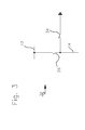
- a circuit 10 generally consists of a bus 12 and several (in the case shown three) primary branches 14, 14', 14" .
- the bus 12 is connected with a measuring device 16, which is provided to allow test of those telecommunication lines (described below), which are to be tested and/or monitored.
- Reference number 18 denotes the telecommunication lines.
- several telecommunication lines 18 are grouped together, with three groups being shown in Figure 1.
- This schematically indicates that several telecommunication lines are, as will be apparent to those skilled in the art, connected with contacts of a particular terminal module.
- one primary branch 14 can be connected with secondary branches 20 as described below, which are in turn connected with the telecommunication lines of a particular module.
- each primary branch 14, 14', 14 " is associated with a particular terminal module.
- this merely represents an example of a structure and any other structure of the mentioned lines is possible that allows the application of the circuit described herein.
- each of the secondary branches 20 comprises a switch 22 to connect and disconnect the secondary branches from the primary branch 14.
- the secondary branches 20 can remain disconnected from the primary branch 14 in an initial state.
- the switch can be changed to a state in which the secondary branch 20 and the primary branch 14 are connected. This is shown for the center secondary branch 24 of the center group of telecommunication lines 18.
- the center primary branch 14' which is connected with secondary branch 24, is connected with the bus 12 via primary switch 26'.
- this center primary branch 14' and the center secondary branch 24 are in use at a certain point in time and measurements can be made utilizing these lines.
- the signal which is taken from that telecommunication line 18', with which the secondary branch 24 is connected, is eventually routed to the measuring device 16 via the secondary branch 24, the primary branch 14' and the bus 12.
- any primary branches, secondary branches and further branches which might be present, remain disconnected from the bus 12 to reduce the parasitic capacitances as far as possible.
- the measuring device 16 is more or less directly connected with the telecommunication line 18' to be measured without any primary branches, which are not in use, being connected therewith.
- those primary branches which are not in use are, as a first step, disconnected from the bus 12.
- they can be connected with ground via switch 26, 26''. This drains any current which may, for example, be induced in primary branches 14 and 14'', to ground.
- Fig. 2 shows a second embodiment of a circuit 30 in accordance with the invention.
- the primary branches 14 are constituted by sub-branches 14a and 14b.
- the circuit as shown in Fig. 1 is "doubled" in order to allow the connection of two separate buses 12a and 12b with particular telecommunication lines.
- two adjacent lines can be measured, for example, to determine crosstalk properties.
- the switch 26, which is provided for each of these sub-branches 14a and 14b has the same effects as described above.
- each of the secondary branches 20, which is connectable with the telecommunication line via switch 22, can be connected with either bus 12a or bus 12b secondary switch 28.
- This secondary switch 28 particularly contributes to the parasitic capacitance, crosstalk or coupling between buses 12a and 12b and has the potential to deteriorate the results of measurements that are made via primary branches 14a and 14b as well as, if applicable, secondary branches 20.
- the possibility of connecting the disconnected branches including switches such as switch 28 with ground, which is realized by switch 26, advantageously improves the accuracy of measurements.
- Fig. 3 shows an arrangement 32 of two switches 26 and 34, which, in this arrangement, essentially performs the same function as switch 26 of the circuit of Fig. 1.
- switch 26 connects the primary branch 14 with the bus 12.
- switch 34 can be brought into the state as shown in Fig. 3 in which the primary branch 14 is connected with ground.
- switches 26 and 34 can be of the same or of a different type. In this context, any types of switches as mentioned above can be used.
Landscapes
- Engineering & Computer Science (AREA)
- Signal Processing (AREA)
- Computer Networks & Wireless Communication (AREA)
- Monitoring And Testing Of Exchanges (AREA)
- Monitoring And Testing Of Transmission In General (AREA)
- Maintenance And Management Of Digital Transmission (AREA)
- Alarm Systems (AREA)
Abstract
Description
- Fig. 1
- shows a first embodiment of a circuit;
- Fig. 2
- shows a second embodiment of a circuit; and
- Fig. 3
- shows an arrangement of two switches.
Claims (14)
- A circuit (10, 30) for providing test and/or monitoring access to at least two telecommunication lines (18), comprising at least one bus (12) and at least two primary branches (14) extending there from, at least one of the primary branches (14) being provided with at least one switch (26, 34), which in a first state connects the primary branch (14) with the bus (12) and in a second state connect the primary branch (14) with ground.
- The circuit in accordance with claim 1 wherein at least one primary branch (14) comprises at least two secondary branches (20), at least one of the secondary branches (20) being provided with a switch (24), which, in a first state, connects the secondary branch (20) with the primary branch (14).
- The circuit in accordance with claim 1 or 2 comprising at least two buses (12a, 12b), at least one of the primary branches being constituted by at least two sub-branches (14a, 14b), each of these sub-branches (14a, 14b) being connected with one bus (12a, 12b), and least one switch (28) being provided for connecting a telecommunication line (18) with a selected one of the buses (12a, 12b).
- The circuit in accordance with any of the preceding claims wherein at least one switch is a relay (26, 22, 28).
- The circuit in accordance with any of the preceding claims wherein at least one switch (26, 22, 28) is remotely controllable.
- A system comprising at least one circuit in accordance with any of the preceding claims and at least one test and/or measurement device.
- A method of providing test and/or monitoring access to a telecommunication line (18), the method involving a circuit (10, 30) comprising at least one bus (12) and at least two primary branches (14) extending from the bus (12) to a telecommunication line (18) each, the primary branches (14) being, in an initial state, connected with ground, the method comprising the step of connecting only that primary branch (14), through which access to a telecommunication line 18 is to be established, with the bus (12).
- The method in accordance with claim 7 wherein at least one primary branch (14) comprises at least two secondary branches (20), the secondary branches (20) being, in an initial state, disconnected from the primary branch (14), the method comprising the step of connecting only that secondary branch (20), through which access to a telecommunication line is to be established, with the primary branch (14).
- The method in accordance with claim 7 or 8 wherein at least one switch (26, 22) is remotely controlled.
- The method in accordance with one of claims 6 to 9 wherein the test serves to locate an open line.
- The method in accordance with one of claims 6 to 9 wherein the test serves to measure physical parameters, such as voltage, frequency-dependent voltage, or interfering voltages.
- The method in accordance with one of claims 6 to 9 wherein the test serves to measure a response of the line to specific, emitted signals.
- A method of retro-fitting an existing test and/or monitoring system, comprising the steps of:a) disconnecting at least one existing circuit for providing test and/or monitoring access, andb) connecting at least one circuit for providing test and/or monitoring access in accordance with one of claims 1 to 5.
- The method in accordance with claim 13 further comprising the step of retro-fitting the existing test and/or monitoring system with at least one test and/or measurement device.
Priority Applications (9)
| Application Number | Priority Date | Filing Date | Title |
|---|---|---|---|
| DE602004023268T DE602004023268D1 (en) | 2004-03-18 | 2004-03-18 | Circuit and method for access to a test and / or monitoring system |
| EP04006533A EP1578147B1 (en) | 2004-03-18 | 2004-03-18 | Circuit and method for providing access to a test and/or monitoring system |
| ES04006533T ES2333012T3 (en) | 2004-03-18 | 2004-03-18 | CIRCUIT AND METHOD TO PROVIDE ACCESS TO A TEST SYSTEM AND / OR SUPERVISION. |
| AT04006533T ATE443973T1 (en) | 2004-03-18 | 2004-03-18 | CIRCUIT AND METHOD FOR ACCESS TO A TEST AND/OR MONITORING SYSTEM |
| BRPI0508837-2A BRPI0508837A (en) | 2004-03-18 | 2005-02-03 | circuit for providing test and / or monitoring access to at least two telecommunication lines, system, method for providing test and / or monitoring access to a telecommunication line, and method for retrofitting an existing test and / or monitoring system |
| CN200580008391.0A CN1934875A (en) | 2004-03-18 | 2005-02-03 | Circuit and method for providing access to a test and/or monitoring system |
| PCT/US2005/003283 WO2005094089A1 (en) | 2004-03-18 | 2005-02-03 | Circuit and method for providing access to a test and/or monitoring system |
| US10/598,927 US7773728B2 (en) | 2004-03-18 | 2005-02-03 | Circuit and method for providing access to a test and/or monitoring system |
| ZA200608657A ZA200608657B (en) | 2004-03-18 | 2006-10-17 | Circuit and method for providing access to a test and/or monitoring system |
Applications Claiming Priority (1)
| Application Number | Priority Date | Filing Date | Title |
|---|---|---|---|
| EP04006533A EP1578147B1 (en) | 2004-03-18 | 2004-03-18 | Circuit and method for providing access to a test and/or monitoring system |
Publications (2)
| Publication Number | Publication Date |
|---|---|
| EP1578147A1 true EP1578147A1 (en) | 2005-09-21 |
| EP1578147B1 EP1578147B1 (en) | 2009-09-23 |
Family
ID=34833640
Family Applications (1)
| Application Number | Title | Priority Date | Filing Date |
|---|---|---|---|
| EP04006533A Expired - Lifetime EP1578147B1 (en) | 2004-03-18 | 2004-03-18 | Circuit and method for providing access to a test and/or monitoring system |
Country Status (9)
| Country | Link |
|---|---|
| US (1) | US7773728B2 (en) |
| EP (1) | EP1578147B1 (en) |
| CN (1) | CN1934875A (en) |
| AT (1) | ATE443973T1 (en) |
| BR (1) | BRPI0508837A (en) |
| DE (1) | DE602004023268D1 (en) |
| ES (1) | ES2333012T3 (en) |
| WO (1) | WO2005094089A1 (en) |
| ZA (1) | ZA200608657B (en) |
Citations (4)
| Publication number | Priority date | Publication date | Assignee | Title |
|---|---|---|---|---|
| WO2001045452A2 (en) * | 1999-12-14 | 2001-06-21 | Adc Telecommunications, Inc. | Systems and methods for electronically managing digital subscriber line (dsl) telecommunications connections |
| US6265842B1 (en) * | 1993-08-25 | 2001-07-24 | Con-X Corporation | Cross-connect method and apparatus |
| WO2003065699A1 (en) * | 2002-01-30 | 2003-08-07 | Tyco Electronics Raychem Nv | Apparatus for management and remote control of electrical characteristics of each wire pairs connected to a telephone exchange and to a distribution frame |
| WO2003079599A2 (en) * | 2002-03-11 | 2003-09-25 | 3M Innovative Properties Company | A measurement arrangement and telecommunications assembly |
Family Cites Families (8)
| Publication number | Priority date | Publication date | Assignee | Title |
|---|---|---|---|---|
| US2885603A (en) | 1955-04-08 | 1959-05-05 | Ncr Co | Pluggable circuit unit |
| FR2732164B1 (en) | 1995-03-20 | 1997-04-30 | Alcatel Cable Interface | HIGH SPEED LINES CONNECTION RULE AND RESULTING CONNECTION ASSEMBLY |
| US5595507A (en) | 1995-05-17 | 1997-01-21 | Lucent Technologies Inc. | Mounting bracket and ground bar for a connector block |
| US5621782A (en) * | 1995-06-02 | 1997-04-15 | Harris Corporation | Test interface adapter emulating on test trunk interface for non-standard central office switch |
| WO1999014917A2 (en) * | 1997-09-19 | 1999-03-25 | Tollgrade Communications, Inc. | Telephony testing system |
| US6654255B2 (en) | 1999-12-02 | 2003-11-25 | Adtran, Inc. | System for mounting data communication equipment |
| US6584148B1 (en) * | 2000-06-02 | 2003-06-24 | Nokia Inc. | System and method for testing digital subscriber lines |
| DE10029870A1 (en) | 2000-06-16 | 2002-01-03 | Rxs Kabelgarnituren Gmbh & Co | Distribution device of a data signal processing system and data signal processing system |
-
2004
- 2004-03-18 ES ES04006533T patent/ES2333012T3/en not_active Expired - Lifetime
- 2004-03-18 AT AT04006533T patent/ATE443973T1/en not_active IP Right Cessation
- 2004-03-18 DE DE602004023268T patent/DE602004023268D1/en not_active Expired - Lifetime
- 2004-03-18 EP EP04006533A patent/EP1578147B1/en not_active Expired - Lifetime
-
2005
- 2005-02-03 US US10/598,927 patent/US7773728B2/en not_active Expired - Fee Related
- 2005-02-03 BR BRPI0508837-2A patent/BRPI0508837A/en not_active IP Right Cessation
- 2005-02-03 WO PCT/US2005/003283 patent/WO2005094089A1/en not_active Ceased
- 2005-02-03 CN CN200580008391.0A patent/CN1934875A/en active Pending
-
2006
- 2006-10-17 ZA ZA200608657A patent/ZA200608657B/en unknown
Patent Citations (4)
| Publication number | Priority date | Publication date | Assignee | Title |
|---|---|---|---|---|
| US6265842B1 (en) * | 1993-08-25 | 2001-07-24 | Con-X Corporation | Cross-connect method and apparatus |
| WO2001045452A2 (en) * | 1999-12-14 | 2001-06-21 | Adc Telecommunications, Inc. | Systems and methods for electronically managing digital subscriber line (dsl) telecommunications connections |
| WO2003065699A1 (en) * | 2002-01-30 | 2003-08-07 | Tyco Electronics Raychem Nv | Apparatus for management and remote control of electrical characteristics of each wire pairs connected to a telephone exchange and to a distribution frame |
| WO2003079599A2 (en) * | 2002-03-11 | 2003-09-25 | 3M Innovative Properties Company | A measurement arrangement and telecommunications assembly |
Non-Patent Citations (1)
| Title |
|---|
| CHANCHIN SU ET AL: "Metrology for analog module testing using analog testability bus", COMPUTER-AIDED DESIGN, 1996. ICCAD-96. DIGEST OF TECHNICAL PAPERS., 1996 IEEE/ACM INTERNATIONAL CONFERENCE ON SAN JOSE, CA, USA 10-14 NOV. 1996, LOS ALAMITOS, CA, USA,IEEE COMPUT. SOC, US, 10 November 1996 (1996-11-10), pages 594 - 599, XP010205439, ISBN: 0-8186-7597-7 * |
Also Published As
| Publication number | Publication date |
|---|---|
| WO2005094089A1 (en) | 2005-10-06 |
| ES2333012T3 (en) | 2010-02-16 |
| EP1578147B1 (en) | 2009-09-23 |
| DE602004023268D1 (en) | 2009-11-05 |
| US7773728B2 (en) | 2010-08-10 |
| ZA200608657B (en) | 2008-06-25 |
| BRPI0508837A (en) | 2007-08-28 |
| US20070283068A1 (en) | 2007-12-06 |
| CN1934875A (en) | 2007-03-21 |
| ATE443973T1 (en) | 2009-10-15 |
Similar Documents
| Publication | Publication Date | Title |
|---|---|---|
| US6724880B1 (en) | Method and apparatus for sparing communications circuits | |
| US6594343B1 (en) | Splitter bypass architecture for testing multiple ports | |
| CN101427614B (en) | Contact bank, measurement arrangement, telecommunications module and telecommunications assembly provided with a contact bank or a measurement arrangement | |
| EP1578147B1 (en) | Circuit and method for providing access to a test and/or monitoring system | |
| US7830669B2 (en) | Contact bank | |
| US7970105B2 (en) | Subscriber line maintenance apparatus and methods | |
| MXPA06010518A (en) | Circuit and method for providing access to a test and/or monitoring system | |
| EP1650900B1 (en) | A user line testing apparatus and broadband/narrowband telecommunication sytem | |
| RU2291584C2 (en) | Metallic testing access for connectors of digital client x-lines | |
| US20070189464A1 (en) | Method for distributing hardware and software resources for high bit rate link control | |
| EP1578144B1 (en) | Modular arrangement in the field of telecommunications | |
| US6535602B1 (en) | Telecommunications wiring device | |
| EP3716596B1 (en) | Testing device for a xdsl distribution unit of a telecommunication system, telecommunication system and method for testing the same | |
| KR200177378Y1 (en) | Connection apparatus for testing in a cable interface board | |
| KR101061511B1 (en) | Remotely controlled communication terminal device | |
| EP2667543B1 (en) | Method for detecting electrical deteriorations in a bus network | |
| CN1620799A (en) | The connection architecture used in the XDSL network and the intermediate distribution frame required by the architecture | |
| Wehrman et al. | Resource switching the cornerstone for a modular scalable test set solution | |
| JPH04157857A (en) | Subscriber line test system | |
| JPH01106550A (en) | Method for testing exchange with remotely installed equipment |
Legal Events
| Date | Code | Title | Description |
|---|---|---|---|
| PUAI | Public reference made under article 153(3) epc to a published international application that has entered the european phase |
Free format text: ORIGINAL CODE: 0009012 |
|
| AK | Designated contracting states |
Kind code of ref document: A1 Designated state(s): AT BE BG CH CY CZ DE DK EE ES FI FR GB GR HU IE IT LI LU MC NL PL PT RO SE SI SK TR |
|
| AX | Request for extension of the european patent |
Extension state: AL LT LV MK |
|
| 17P | Request for examination filed |
Effective date: 20060317 |
|
| AKX | Designation fees paid |
Designated state(s): AT BE BG CH CY CZ DE DK EE ES FI FR GB GR HU IE IT LI LU MC NL PL PT RO SE SI SK TR |
|
| GRAP | Despatch of communication of intention to grant a patent |
Free format text: ORIGINAL CODE: EPIDOSNIGR1 |
|
| GRAS | Grant fee paid |
Free format text: ORIGINAL CODE: EPIDOSNIGR3 |
|
| GRAA | (expected) grant |
Free format text: ORIGINAL CODE: 0009210 |
|
| AK | Designated contracting states |
Kind code of ref document: B1 Designated state(s): AT BE BG CH CY CZ DE DK EE ES FI FR GB GR HU IE IT LI LU MC NL PL PT RO SE SI SK TR |
|
| REG | Reference to a national code |
Ref country code: GB Ref legal event code: FG4D |
|
| REG | Reference to a national code |
Ref country code: CH Ref legal event code: EP |
|
| REG | Reference to a national code |
Ref country code: IE Ref legal event code: FG4D |
|
| REF | Corresponds to: |
Ref document number: 602004023268 Country of ref document: DE Date of ref document: 20091105 Kind code of ref document: P |
|
| PG25 | Lapsed in a contracting state [announced via postgrant information from national office to epo] |
Ref country code: FI Free format text: LAPSE BECAUSE OF FAILURE TO SUBMIT A TRANSLATION OF THE DESCRIPTION OR TO PAY THE FEE WITHIN THE PRESCRIBED TIME-LIMIT Effective date: 20090923 Ref country code: SE Free format text: LAPSE BECAUSE OF FAILURE TO SUBMIT A TRANSLATION OF THE DESCRIPTION OR TO PAY THE FEE WITHIN THE PRESCRIBED TIME-LIMIT Effective date: 20090923 |
|
| REG | Reference to a national code |
Ref country code: ES Ref legal event code: FG2A Ref document number: 2333012 Country of ref document: ES Kind code of ref document: T3 |
|
| PG25 | Lapsed in a contracting state [announced via postgrant information from national office to epo] |
Ref country code: PL Free format text: LAPSE BECAUSE OF FAILURE TO SUBMIT A TRANSLATION OF THE DESCRIPTION OR TO PAY THE FEE WITHIN THE PRESCRIBED TIME-LIMIT Effective date: 20090923 Ref country code: SI Free format text: LAPSE BECAUSE OF FAILURE TO SUBMIT A TRANSLATION OF THE DESCRIPTION OR TO PAY THE FEE WITHIN THE PRESCRIBED TIME-LIMIT Effective date: 20090923 |
|
| NLV1 | Nl: lapsed or annulled due to failure to fulfill the requirements of art. 29p and 29m of the patents act | ||
| PG25 | Lapsed in a contracting state [announced via postgrant information from national office to epo] |
Ref country code: CY Free format text: LAPSE BECAUSE OF FAILURE TO SUBMIT A TRANSLATION OF THE DESCRIPTION OR TO PAY THE FEE WITHIN THE PRESCRIBED TIME-LIMIT Effective date: 20090923 |
|
| PG25 | Lapsed in a contracting state [announced via postgrant information from national office to epo] |
Ref country code: RO Free format text: LAPSE BECAUSE OF FAILURE TO SUBMIT A TRANSLATION OF THE DESCRIPTION OR TO PAY THE FEE WITHIN THE PRESCRIBED TIME-LIMIT Effective date: 20090923 Ref country code: CZ Free format text: LAPSE BECAUSE OF FAILURE TO SUBMIT A TRANSLATION OF THE DESCRIPTION OR TO PAY THE FEE WITHIN THE PRESCRIBED TIME-LIMIT Effective date: 20090923 Ref country code: PT Free format text: LAPSE BECAUSE OF FAILURE TO SUBMIT A TRANSLATION OF THE DESCRIPTION OR TO PAY THE FEE WITHIN THE PRESCRIBED TIME-LIMIT Effective date: 20100125 Ref country code: EE Free format text: LAPSE BECAUSE OF FAILURE TO SUBMIT A TRANSLATION OF THE DESCRIPTION OR TO PAY THE FEE WITHIN THE PRESCRIBED TIME-LIMIT Effective date: 20090923 |
|
| PG25 | Lapsed in a contracting state [announced via postgrant information from national office to epo] |
Ref country code: SK Free format text: LAPSE BECAUSE OF FAILURE TO SUBMIT A TRANSLATION OF THE DESCRIPTION OR TO PAY THE FEE WITHIN THE PRESCRIBED TIME-LIMIT Effective date: 20090923 |
|
| PG25 | Lapsed in a contracting state [announced via postgrant information from national office to epo] |
Ref country code: AT Free format text: LAPSE BECAUSE OF FAILURE TO SUBMIT A TRANSLATION OF THE DESCRIPTION OR TO PAY THE FEE WITHIN THE PRESCRIBED TIME-LIMIT Effective date: 20090923 Ref country code: BE Free format text: LAPSE BECAUSE OF FAILURE TO SUBMIT A TRANSLATION OF THE DESCRIPTION OR TO PAY THE FEE WITHIN THE PRESCRIBED TIME-LIMIT Effective date: 20090923 |
|
| PG25 | Lapsed in a contracting state [announced via postgrant information from national office to epo] |
Ref country code: DK Free format text: LAPSE BECAUSE OF FAILURE TO SUBMIT A TRANSLATION OF THE DESCRIPTION OR TO PAY THE FEE WITHIN THE PRESCRIBED TIME-LIMIT Effective date: 20090923 Ref country code: NL Free format text: LAPSE BECAUSE OF FAILURE TO SUBMIT A TRANSLATION OF THE DESCRIPTION OR TO PAY THE FEE WITHIN THE PRESCRIBED TIME-LIMIT Effective date: 20090923 |
|
| PLBE | No opposition filed within time limit |
Free format text: ORIGINAL CODE: 0009261 |
|
| STAA | Information on the status of an ep patent application or granted ep patent |
Free format text: STATUS: NO OPPOSITION FILED WITHIN TIME LIMIT |
|
| 26N | No opposition filed |
Effective date: 20100624 |
|
| PG25 | Lapsed in a contracting state [announced via postgrant information from national office to epo] |
Ref country code: MC Free format text: LAPSE BECAUSE OF NON-PAYMENT OF DUE FEES Effective date: 20100331 Ref country code: GR Free format text: LAPSE BECAUSE OF FAILURE TO SUBMIT A TRANSLATION OF THE DESCRIPTION OR TO PAY THE FEE WITHIN THE PRESCRIBED TIME-LIMIT Effective date: 20091224 |
|
| REG | Reference to a national code |
Ref country code: CH Ref legal event code: PL |
|
| PG25 | Lapsed in a contracting state [announced via postgrant information from national office to epo] |
Ref country code: IE Free format text: LAPSE BECAUSE OF NON-PAYMENT OF DUE FEES Effective date: 20100318 |
|
| PG25 | Lapsed in a contracting state [announced via postgrant information from national office to epo] |
Ref country code: CH Free format text: LAPSE BECAUSE OF NON-PAYMENT OF DUE FEES Effective date: 20100331 Ref country code: LI Free format text: LAPSE BECAUSE OF NON-PAYMENT OF DUE FEES Effective date: 20100331 |
|
| PG25 | Lapsed in a contracting state [announced via postgrant information from national office to epo] |
Ref country code: IT Free format text: LAPSE BECAUSE OF FAILURE TO SUBMIT A TRANSLATION OF THE DESCRIPTION OR TO PAY THE FEE WITHIN THE PRESCRIBED TIME-LIMIT Effective date: 20090923 |
|
| PGFP | Annual fee paid to national office [announced via postgrant information from national office to epo] |
Ref country code: FR Payment date: 20120319 Year of fee payment: 9 |
|
| PGFP | Annual fee paid to national office [announced via postgrant information from national office to epo] |
Ref country code: GB Payment date: 20120314 Year of fee payment: 9 |
|
| PG25 | Lapsed in a contracting state [announced via postgrant information from national office to epo] |
Ref country code: BG Free format text: LAPSE BECAUSE OF FAILURE TO SUBMIT A TRANSLATION OF THE DESCRIPTION OR TO PAY THE FEE WITHIN THE PRESCRIBED TIME-LIMIT Effective date: 20090923 Ref country code: HU Free format text: LAPSE BECAUSE OF FAILURE TO SUBMIT A TRANSLATION OF THE DESCRIPTION OR TO PAY THE FEE WITHIN THE PRESCRIBED TIME-LIMIT Effective date: 20100324 Ref country code: LU Free format text: LAPSE BECAUSE OF NON-PAYMENT OF DUE FEES Effective date: 20100318 |
|
| PG25 | Lapsed in a contracting state [announced via postgrant information from national office to epo] |
Ref country code: TR Free format text: LAPSE BECAUSE OF FAILURE TO SUBMIT A TRANSLATION OF THE DESCRIPTION OR TO PAY THE FEE WITHIN THE PRESCRIBED TIME-LIMIT Effective date: 20090923 |
|
| PGFP | Annual fee paid to national office [announced via postgrant information from national office to epo] |
Ref country code: ES Payment date: 20120419 Year of fee payment: 9 |
|
| GBPC | Gb: european patent ceased through non-payment of renewal fee |
Effective date: 20130318 |
|
| REG | Reference to a national code |
Ref country code: FR Ref legal event code: ST Effective date: 20131129 |
|
| PG25 | Lapsed in a contracting state [announced via postgrant information from national office to epo] |
Ref country code: GB Free format text: LAPSE BECAUSE OF NON-PAYMENT OF DUE FEES Effective date: 20130318 Ref country code: FR Free format text: LAPSE BECAUSE OF NON-PAYMENT OF DUE FEES Effective date: 20130402 |
|
| REG | Reference to a national code |
Ref country code: ES Ref legal event code: FD2A Effective date: 20140609 |
|
| PG25 | Lapsed in a contracting state [announced via postgrant information from national office to epo] |
Ref country code: ES Free format text: LAPSE BECAUSE OF NON-PAYMENT OF DUE FEES Effective date: 20130319 |
|
| PGFP | Annual fee paid to national office [announced via postgrant information from national office to epo] |
Ref country code: DE Payment date: 20150310 Year of fee payment: 12 |
|
| REG | Reference to a national code |
Ref country code: DE Ref legal event code: R119 Ref document number: 602004023268 Country of ref document: DE |
|
| PG25 | Lapsed in a contracting state [announced via postgrant information from national office to epo] |
Ref country code: DE Free format text: LAPSE BECAUSE OF NON-PAYMENT OF DUE FEES Effective date: 20161001 |