EP1577600A2 - Monitor stand - Google Patents
Monitor stand Download PDFInfo
- Publication number
- EP1577600A2 EP1577600A2 EP05005597A EP05005597A EP1577600A2 EP 1577600 A2 EP1577600 A2 EP 1577600A2 EP 05005597 A EP05005597 A EP 05005597A EP 05005597 A EP05005597 A EP 05005597A EP 1577600 A2 EP1577600 A2 EP 1577600A2
- Authority
- EP
- European Patent Office
- Prior art keywords
- packing
- housing
- opening
- image display
- display device
- Prior art date
- Legal status (The legal status is an assumption and is not a legal conclusion. Google has not performed a legal analysis and makes no representation as to the accuracy of the status listed.)
- Withdrawn
Links
Images



Classifications
-
- F—MECHANICAL ENGINEERING; LIGHTING; HEATING; WEAPONS; BLASTING
- F16—ENGINEERING ELEMENTS AND UNITS; GENERAL MEASURES FOR PRODUCING AND MAINTAINING EFFECTIVE FUNCTIONING OF MACHINES OR INSTALLATIONS; THERMAL INSULATION IN GENERAL
- F16M—FRAMES, CASINGS OR BEDS OF ENGINES, MACHINES OR APPARATUS, NOT SPECIFIC TO ENGINES, MACHINES OR APPARATUS PROVIDED FOR ELSEWHERE; STANDS; SUPPORTS
- F16M11/00—Stands or trestles as supports for apparatus or articles placed thereon ; Stands for scientific apparatus such as gravitational force meters
- F16M11/02—Heads
- F16M11/04—Means for attachment of apparatus; Means allowing adjustment of the apparatus relatively to the stand
- F16M11/06—Means for attachment of apparatus; Means allowing adjustment of the apparatus relatively to the stand allowing pivoting
- F16M11/12—Means for attachment of apparatus; Means allowing adjustment of the apparatus relatively to the stand allowing pivoting in more than one direction
-
- F—MECHANICAL ENGINEERING; LIGHTING; HEATING; WEAPONS; BLASTING
- F16—ENGINEERING ELEMENTS AND UNITS; GENERAL MEASURES FOR PRODUCING AND MAINTAINING EFFECTIVE FUNCTIONING OF MACHINES OR INSTALLATIONS; THERMAL INSULATION IN GENERAL
- F16M—FRAMES, CASINGS OR BEDS OF ENGINES, MACHINES OR APPARATUS, NOT SPECIFIC TO ENGINES, MACHINES OR APPARATUS PROVIDED FOR ELSEWHERE; STANDS; SUPPORTS
- F16M11/00—Stands or trestles as supports for apparatus or articles placed thereon ; Stands for scientific apparatus such as gravitational force meters
- F16M11/20—Undercarriages with or without wheels
- F16M11/24—Undercarriages with or without wheels changeable in height or length of legs, also for transport only, e.g. by means of tubes screwed into each other
- F16M11/26—Undercarriages with or without wheels changeable in height or length of legs, also for transport only, e.g. by means of tubes screwed into each other by telescoping, with or without folding
- F16M11/28—Undercarriages for supports with one single telescoping pillar
-
- F—MECHANICAL ENGINEERING; LIGHTING; HEATING; WEAPONS; BLASTING
- F16—ENGINEERING ELEMENTS AND UNITS; GENERAL MEASURES FOR PRODUCING AND MAINTAINING EFFECTIVE FUNCTIONING OF MACHINES OR INSTALLATIONS; THERMAL INSULATION IN GENERAL
- F16M—FRAMES, CASINGS OR BEDS OF ENGINES, MACHINES OR APPARATUS, NOT SPECIFIC TO ENGINES, MACHINES OR APPARATUS PROVIDED FOR ELSEWHERE; STANDS; SUPPORTS
- F16M11/00—Stands or trestles as supports for apparatus or articles placed thereon ; Stands for scientific apparatus such as gravitational force meters
- F16M11/02—Heads
- F16M11/04—Means for attachment of apparatus; Means allowing adjustment of the apparatus relatively to the stand
- F16M11/06—Means for attachment of apparatus; Means allowing adjustment of the apparatus relatively to the stand allowing pivoting
- F16M11/12—Means for attachment of apparatus; Means allowing adjustment of the apparatus relatively to the stand allowing pivoting in more than one direction
- F16M11/125—Means for attachment of apparatus; Means allowing adjustment of the apparatus relatively to the stand allowing pivoting in more than one direction for tilting and rolling
-
- G—PHYSICS
- G06—COMPUTING OR CALCULATING; COUNTING
- G06F—ELECTRIC DIGITAL DATA PROCESSING
- G06F1/00—Details not covered by groups G06F3/00 - G06F13/00 and G06F21/00
- G06F1/16—Constructional details or arrangements
- G06F1/1601—Constructional details related to the housing of computer displays, e.g. of CRT monitors, of flat displays
-
- F—MECHANICAL ENGINEERING; LIGHTING; HEATING; WEAPONS; BLASTING
- F16—ENGINEERING ELEMENTS AND UNITS; GENERAL MEASURES FOR PRODUCING AND MAINTAINING EFFECTIVE FUNCTIONING OF MACHINES OR INSTALLATIONS; THERMAL INSULATION IN GENERAL
- F16M—FRAMES, CASINGS OR BEDS OF ENGINES, MACHINES OR APPARATUS, NOT SPECIFIC TO ENGINES, MACHINES OR APPARATUS PROVIDED FOR ELSEWHERE; STANDS; SUPPORTS
- F16M2200/00—Details of stands or supports
- F16M2200/04—Balancing means
- F16M2200/048—Balancing means for balancing translational movement of the undercarriage
-
- Y—GENERAL TAGGING OF NEW TECHNOLOGICAL DEVELOPMENTS; GENERAL TAGGING OF CROSS-SECTIONAL TECHNOLOGIES SPANNING OVER SEVERAL SECTIONS OF THE IPC; TECHNICAL SUBJECTS COVERED BY FORMER USPC CROSS-REFERENCE ART COLLECTIONS [XRACs] AND DIGESTS
- Y10—TECHNICAL SUBJECTS COVERED BY FORMER USPC
- Y10S—TECHNICAL SUBJECTS COVERED BY FORMER USPC CROSS-REFERENCE ART COLLECTIONS [XRACs] AND DIGESTS
- Y10S248/00—Supports
- Y10S248/917—Video display screen support
- Y10S248/919—Adjustably orientable video screen support
- Y10S248/92—Angular and linear video display screen support adjustment
Definitions
- the present invention relates to a stand for supporting an image display device, such as a monitor.
- FIG 1 illustrates a perspective view of a related art monitor stand.
- the related art monitor stand is provided with a base 1, a movable column 2, and a hinge 5.
- the base 1 is placed on a floor, and the movable column 2 is movably mounted on the base 1 for movement in an up/down direction.
- the hinge 5 is mounted on top of the movable column 2 for tilting a monitor (not shown) in a front/rear direction.
- a height of the monitor is adjusted by using the movable column 2, and a tilting angle of the monitor is adjusted by using the hinge 5.
- the related art monitor stand has several problems.
- Second, the hinge 5 has many components, such as a plurality of friction springs, or torsion springs, washers, nuts, and so on. Accordingly, much time is required for fabrication of the hinge.
- the present invention is directed to a monitor stand that substantially obviates one or more problems due to limitations and disadvantages of the related art.
- An object of the present invention is to provide a monitor stand which is easy to handle and fabricate. Additional advantages, objects, and features of the invention will be set forth in part in the description which follows and in part will become apparent to those having ordinary skill in the art upon examination of the following or may be learned from practice of the invention. The objectives and other advantages of the invention may be realized and attained by the structure particularly pointed out in the written description and claims hereof as well as the appended drawings.
- a monitor stand includes a base, a cylindrical housing located on the base, the housing having an opened top and bottom, a packing assembly in the base for opening/closing the bottom of the housing, a piston in the housing, the piston being movable up/down, a first elastic member under the piston, for being compressed when the piston moves down, a bracket on a top of the piston, and a tilt/swivel adjusting device having one end fixedly secured to a front of the bracket, and the other end provided to a rear of the monitor, for rotating the monitor in forward/backward or left/right directions when an external force is applied.
- the piston may have a rubber ring on an outside circumference for being in close contact with an inside surface of the housing, and the first elastic member may be a coil spring.
- the tilt/swivel adjusting device includes first and second cylinders fixedly secured to an upper portion of the bracket, first and second rods having first ends horizontally movably inserted in the first and second cylinders respectively, and second ends coupled to a rear of the monitor, and a third supporting rod having one end fixedly secured to a lower portion of the bracket, and the other end coupled to the rear of the monitor.
- the first to third supporting rods include ball joints preferably made of metal at the other ends thereof, and the monitor includes sockets in the rear thereof for receiving the ball joints.
- the packing assembly includes a lever rotatable up/down by an external force, a packing at one end of the lever for opening/closing the bottom of the housing, and a second elastic member secured to opposite sides of the lever, for returning the lever to an original position when the external force applied to the lever is removed.
- the lever includes a sidewardly projecting shaft, and the packing is hinged at one end of the lever.
- the packing may be formed of rubber, and the second elastic member may be a coil spring.
- the base includes a lower base having a space formed therein, the space having the packing assembly mounted therein, and an upper assembly having a hole making the bottom of the housing and the space in communication with one another.
- the packing assembly includes a packing movable in an up/down direction to open/close the bottom of the housing, a button movable forward/backward horizontally to engage with/disengage from the packing, and a third elastic member under the packing such that the third elastic member is compressed when the packing moves down.
- the base includes a step on an underside of an inside of the base, and the button includes a stopper on an upper surface so that the stopper is stopped at the step to prevent the button from falling off the base.
- the packing includes a notch in a lower portion for inserting the button therein.
- the notch includes a first slope at a lower portion, and the button includes a second slope for sliding on the first slope.
- the third elastic member may be a coil spring.
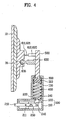
- the monitor stand includes a base 100, a housing 130, a packing assembly 200, a piston 300, a first elastic member 400, a bracket 500, and an orientation (tilt/swivel) adjusting device 600.
- the base 100 may be placed on any horizontal surface, such as a desk, table or floor.
- the base 100 may be a stand-alone base, or may be part of another device, such as the lower keyboard portion of a laptop computer.
- the base 100 may or may not include supplemental weight(s) for stability of the stand when supporting a monitor 10.
- the housing 130 may be cylindrical, rectangular, or other shape with openings in the top and bottom, and is mounted on the base 100.
- the packing assembly 200 is located in the base 100, for closing/opening the opening in the bottom of the housing 130, thereby preventing/enabling air flow in/out of the housing 130.
- the packing assembly 200 includes a lever 210 pivotally connected to the base 100 and movable by an external force.
- a packing 220 is located at one end of the lever 210 for opening/closing the opening in the bottom of the housing 130, and a second elastic members 230 is secured to opposite sides of the lever 210 for returning the lever 210 to an original position if the external force on the lever 210 is removed.
- the lever 210 rotates around a shaft 211, and the packing 220 rotates together with the lever 210, for opening/closing the opening in the bottom of the housing 130.
- the packing 220 is located below the opening in the bottom of the housing.
- the packing 220 may be located inside of the housing 130 to open/close the opening from the top instead of the bottom, provided that the packing 220 is appropriately biased downwardly toward the opening.
- the packing 220 is hinged at an end of the lever 210, for enabling opening/closing of the opening in the bottom of the housing 130 as the packing 220 rotates around a hinge 240 even if the packing 220 is misaligned with the opening in the bottom of the housing 130 because a length of the lever 210 is short/long. It is preferable that the packing 220 is formed of rubber for perfect sealing of the opening in the bottom of the housing 130.
- the second elastic member 230 is a coil spring that acts as a deflection spring, such as a leaf spring.
- the base 100 includes a lower base 110 and an upper base 120 on the lower base 110.
- the lower base 110 has a space 111 formed therein for mounting the packing assembly 200 therein.
- the upper base 120 has a hole 140 for making the bottom of the housing 130 in communication with the space 111.
- the packing 220 is inserted in the hole 140 for opening/closing the opening in the bottom of the housing 130.
- the space 111 has a slot (not shown) for receiving the shaft 211 on the side of the lever 210, and one pair of projections 112 for mounting the springs 230 thereon.
- the springs 230 are coiled springs that act as cantilevered leaf springs to provide a deflection-type restoring force to the lever 210.
- a torsion-type spring located about shaft 211 may be used to provide a restoring force to the lever 210.
- a piston 300 is mounted in the housing 130 so as to be movable in a vertical direction.
- the piston 300 moves up/down in the housing 130, to adjust the height of the monitor 10.
- the piston 300 has a rubber ring 310 on an outside circumferential surface, for being in a close contact with an inside surface of the housing 130.
- the rubber ring 310 seals a gap between the piston 300 and the housing 130 for preventing air from leaking past the piston 300.
- the piston 300 itself may be formed of rubber, or of Teflon with a good anti-abrasion property, or a self-lubricating material.
- the first elastic member 400 under the piston 300 is compressed when the piston 300 moves down. That is, the first elastic member 400 deforms elastically following up/down movement of the piston 300, to apply an upward force to the piston 300.
- the first elastic member 400 is preferably a coil spring, although other compressible elastic elements may be used.
- the first elastic member 400 may be a tension spring device located between the top of the piston 300 and the top of the housing 130 to similarly bias the piston 300 upward.
- the bracket 500 is located at a top of the piston 300, and the tilt/swivel adjusting device 600 is mounted between the bracket 500 and the monitor 10. Because the piston 300 and cylinder of the housing 130 are preferably cylindrical, the piston 300 with the attached bracket 500 may rotate about the vertical axis of the piston 300, thereby permitting rotation of the monitor 10.
- the tilt/swivel adjusting device 600 has one end secured to a front of the bracket 500, and the other end is secured at a rear of the monitor 10, so that the monitor 10 may tilt in forward/backward directions, or swivel in left/right directions. As used herein, tilt refers to the forward/backward rotation of the monitor 10, and swivel refers to the left/right rotation of the monitor 10.
- the tilt/swivel adjusting device 600 includes first and second cylinders 610 and 620, and first, second, and third supporting rods 611, 621, and 630.
- the first and second cylinders 610 and 620 are fixedly secured to an upper portion of the bracket 500.
- the first and second supporting rods 611 and 621 have first ends inserted in the first and second cylinders 610 and 620 respectively, so as to move horizontally, and second ends coupled to the rear of the monitor 10.
- the third supporting rod 630 has a first end fixedly secured to a lower portion of the bracket 500, and a second end coupled to the rear of the monitor 10.
- the first and second supporting rods 611 and 621 slide along insides of the first and second cylinders 610 and 620, respectively, while the third supporting rod 630 does not move, but maintains a fixed state.
- the monitor 10 rotates in forward/backward or left/right directions around the third supporting rod 630 as the first and second supporting rods 611 and 621 move horizontally along the insides of the first and second cylinders 610 and 620.
- the first, second, and third supporting rods 611, 621, and 630 also have ball joints 615, 625, and 635 preferably made of metal at the other ends respectively, and the monitor 10 has sockets 15, 25, and 35 for inserting the ball joints 615, 625, and 635 of the first, second, and third supporting rods 611, 621, and 630 therein, respectively.
- the ball joints 615, 625, and 635 make a spherical motion within the sockets 15, 25, and 35 respectively when the monitor 10 moves forward/backward, or left/right. Accordingly, the ball joints 615, 625, and 635 enable smooth rotation of the monitor 10.
- the apparatus may include no sliding supporting rods at all, and instead be fully supported by the fixed supporting rod 630.
- the apparatus may include only one sliding supporting rod (such as 621) in addition to the fixed supporting rod 630. Such an arrangement would still permit tilting and swiveling of a display attached to the bracket 500, but would restrict the display from rotating between a landscape orientation and a portrait orientation.
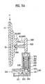
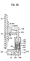
- FIGS. 5A ⁇ 5C illustrate side sectional views of a monitor stand in accordance with a first preferred embodiment of the present invention, showing the steps of a process for adjusting a height of the monitor.
- the user presses down the monitor 10 or the bracket 500, to move the monitor 10 down.
- This causes the piston 300 to move down along an inside of the housing 130, to compress the first elastic member 400.
- air in the housing 130 is also compressed.
- the compressed air pushes out the packing 220, to open the bottom of the housing 130, through which the compressed air escapes from the inside of the housing 130.
- the packing 220 moves up and closes the opening in the bottom of the housing 130 by the elastic force of the second elastic member 230.
- the piston 300 since the inside of the housing 130 is sealed, even if the piston 300 has an upward force applied thereto from the first elastic member 400, the piston 300 does not move. That is, even if a restoring force of the first elastic member 400 exerts an upward force on the piston, a sealed vacuum space under the piston 300 prevents upward movement of the piston 300.
- the user lifts the lever 210 upward, so that the packing 220 hinged at one end of the lever 210 rotates downward around the shaft 211, to open the bottom of the housing 130, and allow introduction of air into the inside of the housing 130.
- the first elastic member 400 pushes up the piston 300.
- the bracket 500 and the monitor 10 coupled to the piston 300 also move up.
- the lever 210 rotates, and returns to an original position by the restoring force of the second elastic member 230.
- the packing 220 also moves together with the lever 210, to close the bottom of the housing 130 again. Accordingly, the inside of the housing 130 is sealed again, to prevent the monitor 10 from moving upward.
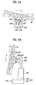
- FIG 6A illustrates a side view showing swiveling of a monitor
- FIG. 6B illustrates a side view showing tilting of a monitor
- the tilt/swivel of the monitor 10 occurs as the first supporting rod 611 and the second supporting rod 621 move horizontally along the first cylinder 610 and the second cylinder 620, respectively. That is, upon application of an external force, lengths of the first and second supporting rods 611 and 621 exposed from the first and second cylinders 610 and 620 change, to move the monitor 10 forward/backward or left/right. In this instance, the monitor 10 rotates forward/backward or left/right around the third supporting rod 630 that has no length change.
- the ball joints 615, 625, and 635 at the first, second, and third supporting rods 611, 621, and the 630 enable smooth rotation of the monitor 10.
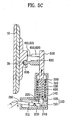
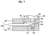
- FIG 7 illustrates a section of a monitor stand in accordance with a second preferred embodiment of the present invention.
- the monitor stand includes a packing assembly 700 having a packing 720, a button 710, and a third elastic member 730.
- the packing moves up/down to open/close the opening in the bottom of the housing 130, and the button 710 moves forward/backward to engage with the packing 720.
- the packing 720 has a notch 721 in a lower portion for receiving the button 710 therein.
- the notch 721 has a first slope 722 in a lower portion, and the button 710 has a second slope 711 for sliding along the first slope 722.
- the first and second slopes 722 and 711 reduce friction between the button 710 and the packing 720, such that the button 710 smoothly moves into or moves away from the notch 721.
- the third elastic member 730 under the packing 720 is compressed when the packing 720 moves down. That is, the third elastic member 730 is compressed when the packing 720 is moved down by an external force, and is restored to an original position when the external force is removed, to return the packing 720 to an original position.
- the third elastic member 730 is preferably a coil spring.
- a step 121 is located on an inside of the base 100, and the button 710 has a stopper 712 on an upper surface so that the stopper 712 is stopped at the step 121 to prevent the button 710 from falling off the base 100. Accordingly, inadvertent disassembly of the button 710 from the base 100 during assembly or transportation of the monitor 10 for packaging can be prevented.
- the step 121 is located on an underside surface of the upper base 120.
- FIGS. 8A and 8B illustrate sections of a monitor stand in accordance with the second preferred embodiment of the present invention, showing the steps of a process for adjusting a height of the monitor.
- the user presses down the monitor 10 or the bracket 500 with a force F, to move the monitor 10 down (see FIG 5A). Accordingly, the piston 300 moves down along an inside of the housing 130, to compress the first elastic member 400, and compress air inside of the housing 130.
- the compressed air makes the packing 720 move down, to open the bottom of the housing 130, and the compressed air escapes from the inside of the housing 130 through the opened bottom of the housing 130.
- the third elastic member 730 is compressed as the packing 720 moves down.
- the packing 720 moves upward by the restoring force of the third elastic member 730, until the packing 720 closes the bottom of the housing 130. In this instance, an inside space of the housing 130 under the piston 300 is sealed, and the piston 300 does not move.
- the user pushes the button 710.
- the button 710 is inserted in the notch 721 in the packing 720, to move the packing 720 downwardly to compress the third elastic member 730 and open the bottom of the housing 130, allowing air to be introduced into the inside of the housing 130.
- the first elastic member 400 moves the piston 300 upward.
- the monitor 10 also moves up.
- the packing 720 moves upward by the restoring force of the third elastic member 730.
- the button 710 moves away from the notch 721 as the second slope 711 slides on the first slope 722.
- the packing 720 moves upward by the third elastic member 730, to close the bottom of the housing 130.
- the inside space of the housing 130 is sealed to prevent the piston 300 from moving upward.
- the monitor stand has several advantages. First, the height adjustment of the monitor is made easier by the present invention, which enhances product satisfaction of the user. Second, since the hinge can be dispensed with for monitor tilt/swivel, the time required for fabrication of the hinge is saved, and an overall assembly process becomes easier.
- a monitor stand includes a base, a cylindrical housing located on the base, the housing having an opened top and bottom, and a packing assembly in the base for opening/closing the bottom of the housing.
- a piston is located in the housing, the piston being movable up/down.
- a first elastic member is located under the piston, for being compressed when the piston moves down.
- a bracket is located on a top of the piston, and a tilt/swivel adjusting device has one end fixedly secured to a front of the bracket, and the other end provided to a rear of the monitor. The tilt/swivel adjusting device permits the monitor to tilt forward/backward, or swivel left/right when an external force is applied.
- the monitor stand is easy to handle and fabricate.
Landscapes
- Engineering & Computer Science (AREA)
- General Engineering & Computer Science (AREA)
- Mechanical Engineering (AREA)
- Theoretical Computer Science (AREA)
- Computer Hardware Design (AREA)
- Human Computer Interaction (AREA)
- Physics & Mathematics (AREA)
- General Physics & Mathematics (AREA)
- Devices For Indicating Variable Information By Combining Individual Elements (AREA)
Abstract
Description
Claims (12)
- A stand for an image display device (10), comprising:a base (100);a housing (130) located on said base (100), said housing (130) having an opening in a bottom portion thereof;a packing assembly (200;700) for opening/closing said opening in said bottom portion of said housing (130);a piston (300) located in said housing (130), said piston (300) being movable up and down;a first elastic member (400) for biasing said piston (300) in one direction;a bracket (500) connected to said piston (300); andan orientation adjusting device (600) having a first portion fixedly secured to said bracket (500), and a second portion provided to a rear of an image display device (10), said orientation adjusting device (600) permitting tilting of the image display device (10) in a forward/backward direction about a substantially horizontal axis when an external force is applied thereto.
- The stand as claimed in claim 1, wherein the orientation adjusting device (600) comprises:a second cylinder (620) fixedly secured to said bracket (500); anda second rod (621) having a first end slidably movable within said second cylinder (620), and a second end including a ball (625) receivable in a corresponding socket (25) located in the rear of the image display device (10).
- The stand as claimed in claims 1 or 2, wherein said packing assembly (700) comprises:a packing (720) movable in an up and down direction to open and close said opening in said bottom portion of said housing (130);a button (710) movable forward and backward to engage and disengage with said packing (720) so as to move said packing (720) away from and toward said opening; anda third elastic member (730) for biasing said packing (720) toward said opening.
- The stand as claimed in claim 1, wherein the orientation adjusting device comprises:wherein said second ends of said first rod (611), said second rod (621) and said fixed rod (630) include balls (615,625,635) which are receivable in corresponding sockets (15,25,35) located in the rear of the image display device (10), to form ball-and-socket joints between said rods (611,621,630) and the image display device (10).a first cylinder (610) fixedly secured to said bracket (500);a first rod (611) having a first end slidably movable within said first cylinder (610), and a second end coupled to a rear of the image display device (10);a second cylinder (620) fixedly secured to said bracket (500) ;a second rod (621) having a first end slidably movable within said second cylinder (620), and a second end coupled to a rear of the image display device (10); anda fixed rod (630) having a first end fixedly secured to said bracket (500), and a second end coupled to the rear of the image display device (10),
- The stand as claimed in claim 4, wherein said packing assembly (200) comprises:a lever (210) located in said base (100) and pivotable up and down by an external force;a packing (220) hinged at one end of said lever (210) and located in said base (100) for opening and closing said opening in said bottom portion of said housing (130); anda second elastic member (230) for returning said lever (210) to an original position when the external force applied to said lever (210) is removed.
- The stand as claimed in claim 4, wherein said packing assembly (700) comprises:wherein said packing (720) includes a notch (721) in a lower portion thereof for receiving a complementary portion of said button (710) therein, so that movement of said button (710) in one direction moves said packing (720) in an orthogonal second direction, anda packing (720) movable in an up and down direction to open and close said opening in said bottom portion of said housing (130);a button (710) movable forward and backward to engage and disengage with said packing (720) so as to move said packing (720) away from and toward said opening; anda third elastic member (730) for biasing said packing (720) toward said opening,
wherein said notch (721) includes a first sloping surface (722), and said complementary portion of said button (710) includes a second sloping surface (711) for sliding on said first sloping surface (722). - A stand for an image display device (10), comprising:a base (100);a housing (130) located on said base (100), said housing (130) having an opening in a bottom portion thereof ;a packing assembly (200; 700) for opening/closing said opening in said bottom portion of said housing;a piston (300) located in said housing (130), said piston (300) being movable up and down;a first elastic member (400) for biasing said piston (300) in one direction;a bracket (500) connected to said piston; andan orientation adjusting device (600) having a first portion fixedly secured to said bracket (500), and a second portion provided to a rear of an image display device (10), said orientation adjusting device (600) permitting swiveling of the image display device (10) in a left/right direction about a substantially vertical axis when an external force is applied thereto.
- The stand as claimed in claim 7, wherein said orientation adjusting device (600) comprises:a first cylinder (610) fixedly secured to said bracket (500);a first rod (611) having a first end slidably movable within said first cylinder (610), and a second end coupled to a rear of the image display device (10); anda fixed rod (630) having a first end fixedly secured to said bracket (500), and a second end coupled to the rear of the image display device (10).
- The stand as claimed in claim 7 or 8, wherein said packing assembly (200) comprises:a lever (210) located in said base (100) and pivotable up and down by an external force;a packing (220) at one end of said lever (210) for opening and closing said opening in said bottom portion of said housing (130); anda second elastic member (230) for returning said lever (210) to an original position when the external force applied to said lever (210) is removed.
- The stand as claimed in claim 7 or 8, wherein said packing assembly (700) comprises:a packing (720) movable in an up and down direction to open and close said opening in said bottom portion of said housing (130);a button (710) movable forward and backward to engage and disengage with said packing (720) so as to move said packing (720) away from and toward said opening; anda third elastic member (730) for biasing said packing (720) toward said opening.
- A stand for an image display device (10), comprising:an orientation adjusting device (600) permitting tilting and swiveling of an image display device (10) in forward/backward and left/right directions about substantially horizontal and vertical axes when an external force is applied thereto, said orientation adjusting device (600) comprising:a first cylinder (610) fixedly secured to a support bracket (500);a first rod (611) having a first end slidably movable within said first cylinder (610), and a second end coupled to a rear of the image display device (10); anda fixed rod (630) having a first end fixedly secured to the bracket (500), and a second end coupled to the rear of the image display device (10).
- The stand as claimed in claim 11, wherein said orientation adjusting device (600) further comprises:a second cylinder (620) fixedly secured to the bracket (500); anda second rod (621) having a first end slidably movable within said second cylinder (620), and a second end including a ball (625) receivable in a corresponding socket (25) located in the rear of the image display device (10).
Priority Applications (1)
| Application Number | Priority Date | Filing Date | Title |
|---|---|---|---|
| EP07011170A EP1821028A1 (en) | 2004-03-15 | 2005-03-15 | Monitor stand |
Applications Claiming Priority (2)
| Application Number | Priority Date | Filing Date | Title |
|---|---|---|---|
| KR10-2004-0017363A KR100531313B1 (en) | 2004-03-15 | 2004-03-15 | stand for display system |
| KR2004017363 | 2004-03-15 |
Related Child Applications (1)
| Application Number | Title | Priority Date | Filing Date |
|---|---|---|---|
| EP07011170A Division EP1821028A1 (en) | 2004-03-15 | 2005-03-15 | Monitor stand |
Publications (2)
| Publication Number | Publication Date |
|---|---|
| EP1577600A2 true EP1577600A2 (en) | 2005-09-21 |
| EP1577600A3 EP1577600A3 (en) | 2005-11-23 |
Family
ID=36147016
Family Applications (2)
| Application Number | Title | Priority Date | Filing Date |
|---|---|---|---|
| EP05005597A Withdrawn EP1577600A3 (en) | 2004-03-15 | 2005-03-15 | Monitor stand |
| EP07011170A Withdrawn EP1821028A1 (en) | 2004-03-15 | 2005-03-15 | Monitor stand |
Family Applications After (1)
| Application Number | Title | Priority Date | Filing Date |
|---|---|---|---|
| EP07011170A Withdrawn EP1821028A1 (en) | 2004-03-15 | 2005-03-15 | Monitor stand |
Country Status (6)
| Country | Link |
|---|---|
| US (2) | US7392965B2 (en) |
| EP (2) | EP1577600A3 (en) |
| KR (1) | KR100531313B1 (en) |
| CN (1) | CN100559511C (en) |
| MX (1) | MXPA05002858A (en) |
| TW (1) | TWI263447B (en) |
Cited By (2)
| Publication number | Priority date | Publication date | Assignee | Title |
|---|---|---|---|---|
| EP1821028A1 (en) * | 2004-03-15 | 2007-08-22 | LG Electronics Inc. | Monitor stand |
| GB2438581A (en) * | 2006-05-31 | 2007-12-05 | Colebrook Bosson Saunders Prod | Adjustable support bracket for a flat-screen monitor |
Families Citing this family (54)
| Publication number | Priority date | Publication date | Assignee | Title |
|---|---|---|---|---|
| AT8874U1 (en) * | 2005-09-14 | 2007-01-15 | Funworld Ag | DEVICE FOR INFORMATION PLAYBACK, ENTERTAINMENT AND / OR DATA PROCESSING |
| TWI266577B (en) * | 2005-09-14 | 2006-11-11 | Benq Corp | Multifunction base and computer utilizing the same |
| US7316377B2 (en) * | 2006-01-24 | 2008-01-08 | Ole Falk Smed | Flat panel monitor mount with low profile ball and socket swivel and tilter mount |
| TWI321678B (en) | 2006-04-21 | 2010-03-11 | Qisda Corp | Base for display device |
| CN100573730C (en) * | 2006-05-08 | 2009-12-23 | 明基电通股份有限公司 | Display base |
| KR100833377B1 (en) * | 2006-10-25 | 2008-05-28 | 엘지전자 주식회사 | Height adjustment device of video display device and video display device |
| CN101276650B (en) * | 2007-03-30 | 2010-09-29 | 群康科技(深圳)有限公司 | Height regulating device and display device using the same |
| CN101286371B (en) * | 2007-04-13 | 2010-09-29 | 群康科技(深圳)有限公司 | Height regulator and display apparatus adopting the height regulator |
| US7748670B1 (en) * | 2008-02-11 | 2010-07-06 | Veldez Steven C | Television rotational support apparatus |
| KR100955480B1 (en) * | 2009-03-12 | 2010-04-30 | 삼성전자주식회사 | Supporting device for display unit and display unit having the same |
| CN101996522A (en) * | 2009-08-11 | 2011-03-30 | 瀚斯宝丽股份有限公司 | Display with multi-directional rotary double-screen structure |
| KR101597827B1 (en) * | 2009-08-11 | 2016-02-25 | 엘지전자 주식회사 | Stand device of display device |
| TWI393441B (en) * | 2009-08-12 | 2013-04-11 | Multi-directional rotation of the dual-screen structure of the display | |
| KR20110026655A (en) * | 2009-09-08 | 2011-03-16 | 삼성전자주식회사 | Lifting unit of image display device and image display device having same |
| JP4923121B2 (en) * | 2010-02-25 | 2012-04-25 | 東芝テック株式会社 | Display device and display device system |
| USD637602S1 (en) * | 2010-07-16 | 2011-05-10 | Xfx Creation, Inc. | Monitor stand |
| US8702046B2 (en) | 2010-07-26 | 2014-04-22 | L&P Property Management Company | Mounting device |
| KR101162949B1 (en) | 2010-11-22 | 2012-07-05 | (주)옵티스 | Device for controlling imaging angle of 3d camera |
| TWI521967B (en) * | 2011-11-09 | 2016-02-11 | Jarllytec Co Ltd | Screen support frame |
| KR101877061B1 (en) * | 2012-03-23 | 2018-07-10 | 엘지전자 주식회사 | Display apparatus |
| TWI486060B (en) * | 2012-07-25 | 2015-05-21 | Jarllytec Co Ltd | Support structure (b) |
| USD755797S1 (en) * | 2014-02-12 | 2016-05-10 | C.D. Great Furniture Co., Ltd. | Monitor stand |
| CN104517531B (en) * | 2014-12-29 | 2017-04-26 | 余姚市利佛德汽车零部件有限公司 | Display |
| CN105987235B (en) * | 2015-01-30 | 2018-05-29 | 佛山高富中石油燃料沥青有限责任公司 | The support device that a kind of support force is stablized |
| USD788782S1 (en) * | 2015-07-20 | 2017-06-06 | Lg Elctronics Inc. | Stand for monitor |
| CN105135165B (en) * | 2015-07-30 | 2017-04-05 | 罗景耀 | The rotary connector of panel computer or handset mounting |
| TWI573950B (en) * | 2015-10-26 | 2017-03-11 | 緯創資通股份有限公司 | Electronic device and bracket that can be automatically raised and selectively rotated |
| KR20170105865A (en) * | 2016-03-10 | 2017-09-20 | 삼성전자주식회사 | Display apparatus |
| US10504319B2 (en) | 2016-12-29 | 2019-12-10 | Video Gaming Technologies, Inc. | Gaming machine including display transition system |
| CN106782135A (en) * | 2017-03-17 | 2017-05-31 | 杭州快步展示科技有限公司 | A kind of intelligent LED display |
| USD865771S1 (en) * | 2017-06-12 | 2019-11-05 | Elo Touch Solutions, Inc. | Display stand |
| US11306865B1 (en) | 2017-06-22 | 2022-04-19 | Russ Bassett Corporation | Quick connect having a secured position and a release position |
| TWM553536U (en) * | 2017-06-26 | 2017-12-21 | 信錦企業股份有限公司 | Supporting module |
| TWM557948U (en) * | 2017-10-07 | 2018-04-01 | 信錦企業股份有限公司 | Supporting frame |
| TWD193993S (en) * | 2018-05-03 | 2018-11-11 | 技嘉科技股份有限公司 | Base of monitor |
| TWI685826B (en) * | 2018-05-16 | 2020-02-21 | 明基電通股份有限公司 | Display device |
| KR102629989B1 (en) * | 2018-09-06 | 2024-01-29 | 삼성전자주식회사 | Display apparatus |
| CN109377896B (en) * | 2018-12-12 | 2020-10-16 | 湖南合利来智慧显示科技有限公司 | Human body induction interaction LED display screen |
| KR102689703B1 (en) * | 2019-01-14 | 2024-07-31 | 삼성전자주식회사 | Stand and display apparatus including the same |
| CN109917855A (en) | 2019-03-04 | 2019-06-21 | 联想(北京)有限公司 | A kind of electronic equipment |
| CN111746416A (en) * | 2019-03-28 | 2020-10-09 | 比亚迪股份有限公司 | The actuator of the display terminal and the vehicle with the same |
| USD903615S1 (en) * | 2019-09-18 | 2020-12-01 | Dell Products L.P. | Display stand |
| WO2021107687A1 (en) | 2019-11-27 | 2021-06-03 | 주식회사 도트힐 | Display mounting device for posture correction, and display mounting control system using same |
| CN111853464B (en) * | 2020-07-31 | 2021-10-29 | 深圳市智兴智造科技有限公司 | Free-rotation all-in-one computer |
| CN111928072B (en) * | 2020-08-07 | 2021-04-20 | 苏州艾宾斯信息技术有限公司 | Interactive computer information display device |
| CN112016453B (en) * | 2020-08-27 | 2023-04-18 | 湖北众堃科技股份有限公司 | Safety inspection device based on AI intelligent recognition |
| CN114458923A (en) * | 2020-11-09 | 2022-05-10 | 江苏蒙苏自动化系统工程有限公司 | Multi-angle monitoring equipment |
| CN112524427B (en) * | 2020-12-19 | 2022-04-12 | 枣庄科顺数码有限公司 | Adjustable base for computer display |
| CN112682640B (en) * | 2020-12-21 | 2022-08-19 | 内蒙古师范大学 | Stable sliding mechanism for digital media art design shooting device |
| CN112524430B (en) * | 2020-12-24 | 2022-06-10 | 广东思程科技有限公司 | Novel video monitoring equipment with adjustable monitoring height |
| CN112879746B (en) * | 2021-01-25 | 2023-04-18 | 山东五棵松电气科技有限公司 | Intelligent face identification system terminal equipment of building |
| JP1734069S (en) * | 2021-12-23 | 2023-01-10 | monitor stand | |
| CA213986S (en) * | 2021-12-23 | 2023-06-28 | Lg Electronics Inc | Stand for a monitor |
| CN115628364B (en) * | 2022-10-17 | 2023-06-27 | 江苏财经职业技术学院 | Live broadcast auxiliary assembly of cross-border electricity business |
Citations (1)
| Publication number | Priority date | Publication date | Assignee | Title |
|---|---|---|---|---|
| US20040004165A1 (en) * | 2002-07-06 | 2004-01-08 | Samsung Electronics Co., Ltd. | Display apparatus |
Family Cites Families (17)
| Publication number | Priority date | Publication date | Assignee | Title |
|---|---|---|---|---|
| US3381926A (en) | 1966-10-20 | 1968-05-07 | Edward E. Fritz | Adjustable stool |
| US4678295A (en) * | 1985-04-05 | 1987-07-07 | Magna International Inc | Memory positioning system for remote control rear-view mirror |
| DE3635920C1 (en) | 1986-10-22 | 1988-06-01 | Junghans Gmbh Geb | Motor-driven adjustment device of a vehicle rearview mirror |
| US5881986A (en) * | 1996-02-02 | 1999-03-16 | Hegarty; David | Document support monitor and engageable universally positionable document holder |
| KR100212313B1 (en) * | 1996-11-06 | 1999-08-02 | 윤종용 | Lcd display device |
| KR200204161Y1 (en) * | 1997-12-12 | 2000-12-01 | 윤종용 | Flat panel display with hinged connections |
| EP0989479B1 (en) * | 1998-09-21 | 2004-06-02 | Hewlett-Packard Company, A Delaware Corporation | Rotatable display apparatus |
| US6343006B1 (en) * | 1998-11-20 | 2002-01-29 | Jerry Moscovitch | Computer display screen system and adjustable screen mount, and swinging screens therefor |
| US6108195A (en) | 1998-12-11 | 2000-08-22 | Inclose Design, Inc. | Computer system having thin-profile display with removable connector assembly |
| US6181390B1 (en) * | 1999-01-27 | 2001-01-30 | Compal Electronics, Inc. | Display holder with multiple side frames |
| JP2001042779A (en) | 1999-07-29 | 2001-02-16 | Toshiba Corp | Personal computer |
| JP2002077775A (en) | 2000-08-30 | 2002-03-15 | Masatoshi Yamamoto | Monitor and monitor pad |
| AU2002225924A1 (en) * | 2000-12-01 | 2002-06-11 | John E. Larson | Unaligned multiple-column height adjustable pedestals for tables and chairs that tilt and slide |
| US6554459B2 (en) * | 2001-03-28 | 2003-04-29 | Lowel-Light Manufacturing, Inc. | Support bracket for light stand |
| US6478275B1 (en) * | 2001-08-31 | 2002-11-12 | Min Hwa Huang | Support device for monitor, displayer or other object |
| KR100630969B1 (en) * | 2002-08-24 | 2006-10-02 | 삼성전자주식회사 | Display device |
| KR100531313B1 (en) | 2004-03-15 | 2005-11-29 | 엘지전자 주식회사 | stand for display system |
-
2004
- 2004-03-15 KR KR10-2004-0017363A patent/KR100531313B1/en not_active Expired - Fee Related
-
2005
- 2005-03-14 TW TW094107637A patent/TWI263447B/en active
- 2005-03-14 US US11/078,409 patent/US7392965B2/en not_active Expired - Fee Related
- 2005-03-15 CN CNB2005100550360A patent/CN100559511C/en not_active Expired - Fee Related
- 2005-03-15 MX MXPA05002858A patent/MXPA05002858A/en not_active Application Discontinuation
- 2005-03-15 EP EP05005597A patent/EP1577600A3/en not_active Withdrawn
- 2005-03-15 EP EP07011170A patent/EP1821028A1/en not_active Withdrawn
-
2007
- 2007-01-25 US US11/657,573 patent/US7395992B2/en not_active Expired - Fee Related
Patent Citations (1)
| Publication number | Priority date | Publication date | Assignee | Title |
|---|---|---|---|---|
| US20040004165A1 (en) * | 2002-07-06 | 2004-01-08 | Samsung Electronics Co., Ltd. | Display apparatus |
Cited By (4)
| Publication number | Priority date | Publication date | Assignee | Title |
|---|---|---|---|---|
| EP1821028A1 (en) * | 2004-03-15 | 2007-08-22 | LG Electronics Inc. | Monitor stand |
| US7392965B2 (en) | 2004-03-15 | 2008-07-01 | Lg Electronics Inc. | Monitor stand |
| US7395992B2 (en) | 2004-03-15 | 2008-07-08 | Lg Electronics Inc. | Monitor stand |
| GB2438581A (en) * | 2006-05-31 | 2007-12-05 | Colebrook Bosson Saunders Prod | Adjustable support bracket for a flat-screen monitor |
Also Published As
| Publication number | Publication date |
|---|---|
| KR100531313B1 (en) | 2005-11-29 |
| EP1821028A1 (en) | 2007-08-22 |
| US20050199773A1 (en) | 2005-09-15 |
| TW200534708A (en) | 2005-10-16 |
| US7392965B2 (en) | 2008-07-01 |
| US7395992B2 (en) | 2008-07-08 |
| MXPA05002858A (en) | 2005-10-05 |
| KR20050092239A (en) | 2005-09-21 |
| CN100559511C (en) | 2009-11-11 |
| TWI263447B (en) | 2006-10-01 |
| US20070158510A1 (en) | 2007-07-12 |
| CN1670866A (en) | 2005-09-21 |
| EP1577600A3 (en) | 2005-11-23 |
Similar Documents
| Publication | Publication Date | Title |
|---|---|---|
| US7392965B2 (en) | Monitor stand | |
| CN101034593B (en) | Display device | |
| KR100628119B1 (en) | Flat panel monitor | |
| US4415136A (en) | Pedestal for consoles | |
| US7331551B2 (en) | Multiple electronic device reorienting support | |
| CN1937090B (en) | Display device | |
| US6970202B1 (en) | Device for mounting a camera on a computer | |
| US6220433B1 (en) | Golf bag with stand device to maintain bag towards upright position | |
| US20050265712A1 (en) | Three way video camera base | |
| US7213792B2 (en) | Height adjustable and pivotable monitor assembly | |
| US20070194183A1 (en) | Stand of display device | |
| US8047487B2 (en) | Display apparatus having adjustable supporting unit | |
| JPWO2003050787A1 (en) | Display lift adjustment device | |
| KR20070057911A (en) | Rollable display device | |
| US8243213B2 (en) | Monitor apparatus | |
| US6364275B1 (en) | Rotary load counterbalancing mechanisms | |
| JP3096746U (en) | LCD television | |
| AU746493B2 (en) | Improvements in or relating to tiltable mountings for TV cameras | |
| CN110412824B (en) | Height adjusting mechanism and projection curtain with same | |
| CN115596972A (en) | Display support with sliding rail structure and display device thereof | |
| CN220416904U (en) | Folding support frame | |
| KR100829039B1 (en) | LCD monitor hinge | |
| JPH0638200A (en) | Camera support mechanism in picture transmitter | |
| KR0181122B1 (en) | Chest pad of a camera | |
| JPH0631760U (en) | Portable walker |
Legal Events
| Date | Code | Title | Description |
|---|---|---|---|
| PUAI | Public reference made under article 153(3) epc to a published international application that has entered the european phase |
Free format text: ORIGINAL CODE: 0009012 |
|
| AK | Designated contracting states |
Kind code of ref document: A2 Designated state(s): AT BE BG CH CY CZ DE DK EE ES FI FR GB GR HU IE IS IT LI LT LU MC NL PL PT RO SE SI SK TR |
|
| AX | Request for extension of the european patent |
Extension state: AL BA HR LV MK YU |
|
| PUAL | Search report despatched |
Free format text: ORIGINAL CODE: 0009013 |
|
| AK | Designated contracting states |
Kind code of ref document: A3 Designated state(s): AT BE BG CH CY CZ DE DK EE ES FI FR GB GR HU IE IS IT LI LT LU MC NL PL PT RO SE SI SK TR |
|
| AX | Request for extension of the european patent |
Extension state: AL BA HR LV MK YU |
|
| RIC1 | Information provided on ipc code assigned before grant |
Ipc: 7F 16M 11/28 B Ipc: 7F 16M 11/12 A |
|
| 17P | Request for examination filed |
Effective date: 20060523 |
|
| AKX | Designation fees paid |
Designated state(s): AT BE BG CH CY CZ DE DK EE ES FI FR GB GR HU IE IS IT LI LT LU MC NL PL PT RO SE SI SK TR |
|
| 17Q | First examination report despatched |
Effective date: 20061120 |
|
| GRAP | Despatch of communication of intention to grant a patent |
Free format text: ORIGINAL CODE: EPIDOSNIGR1 |
|
| STAA | Information on the status of an ep patent application or granted ep patent |
Free format text: STATUS: THE APPLICATION IS DEEMED TO BE WITHDRAWN |
|
| 18D | Application deemed to be withdrawn |
Effective date: 20120424 |