EP1577523A2 - Verminderung der Abgasemissionen einer Maschine mit elektromechanischen Ventilen - Google Patents
Verminderung der Abgasemissionen einer Maschine mit elektromechanischen Ventilen Download PDFInfo
- Publication number
- EP1577523A2 EP1577523A2 EP05004579A EP05004579A EP1577523A2 EP 1577523 A2 EP1577523 A2 EP 1577523A2 EP 05004579 A EP05004579 A EP 05004579A EP 05004579 A EP05004579 A EP 05004579A EP 1577523 A2 EP1577523 A2 EP 1577523A2
- Authority
- EP
- European Patent Office
- Prior art keywords
- cylinder
- engine
- valve
- valves
- intake
- Prior art date
- Legal status (The legal status is an assumption and is not a legal conclusion. Google has not performed a legal analysis and makes no representation as to the accuracy of the status listed.)
- Granted
Links
Images


Classifications
-
- F—MECHANICAL ENGINEERING; LIGHTING; HEATING; WEAPONS; BLASTING
- F02—COMBUSTION ENGINES; HOT-GAS OR COMBUSTION-PRODUCT ENGINE PLANTS
- F02D—CONTROLLING COMBUSTION ENGINES
- F02D41/00—Electrical control of supply of combustible mixture or its constituents
- F02D41/0002—Controlling intake air
-
- F—MECHANICAL ENGINEERING; LIGHTING; HEATING; WEAPONS; BLASTING
- F01—MACHINES OR ENGINES IN GENERAL; ENGINE PLANTS IN GENERAL; STEAM ENGINES
- F01L—CYCLICALLY OPERATING VALVES FOR MACHINES OR ENGINES
- F01L13/00—Modifications of valve-gear to facilitate reversing, braking, starting, changing compression ratio, or other specific operations
- F01L13/0005—Deactivating valves
-
- F—MECHANICAL ENGINEERING; LIGHTING; HEATING; WEAPONS; BLASTING
- F02—COMBUSTION ENGINES; HOT-GAS OR COMBUSTION-PRODUCT ENGINE PLANTS
- F02D—CONTROLLING COMBUSTION ENGINES
- F02D13/00—Controlling the engine output power by varying inlet or exhaust valve operating characteristics, e.g. timing
- F02D13/02—Controlling the engine output power by varying inlet or exhaust valve operating characteristics, e.g. timing during engine operation
- F02D13/0203—Variable control of intake and exhaust valves
- F02D13/0215—Variable control of intake and exhaust valves changing the valve timing only
-
- F—MECHANICAL ENGINEERING; LIGHTING; HEATING; WEAPONS; BLASTING
- F02—COMBUSTION ENGINES; HOT-GAS OR COMBUSTION-PRODUCT ENGINE PLANTS
- F02D—CONTROLLING COMBUSTION ENGINES
- F02D13/00—Controlling the engine output power by varying inlet or exhaust valve operating characteristics, e.g. timing
- F02D13/02—Controlling the engine output power by varying inlet or exhaust valve operating characteristics, e.g. timing during engine operation
- F02D13/0223—Variable control of the intake valves only
- F02D13/0234—Variable control of the intake valves only changing the valve timing only
-
- F—MECHANICAL ENGINEERING; LIGHTING; HEATING; WEAPONS; BLASTING
- F02—COMBUSTION ENGINES; HOT-GAS OR COMBUSTION-PRODUCT ENGINE PLANTS
- F02D—CONTROLLING COMBUSTION ENGINES
- F02D13/00—Controlling the engine output power by varying inlet or exhaust valve operating characteristics, e.g. timing
- F02D13/02—Controlling the engine output power by varying inlet or exhaust valve operating characteristics, e.g. timing during engine operation
- F02D13/0253—Fully variable control of valve lift and timing using camless actuation systems such as hydraulic, pneumatic or electromagnetic actuators, e.g. solenoid valves
-
- F—MECHANICAL ENGINEERING; LIGHTING; HEATING; WEAPONS; BLASTING
- F02—COMBUSTION ENGINES; HOT-GAS OR COMBUSTION-PRODUCT ENGINE PLANTS
- F02D—CONTROLLING COMBUSTION ENGINES
- F02D13/00—Controlling the engine output power by varying inlet or exhaust valve operating characteristics, e.g. timing
- F02D13/02—Controlling the engine output power by varying inlet or exhaust valve operating characteristics, e.g. timing during engine operation
- F02D13/0257—Independent control of two or more intake or exhaust valves respectively, i.e. one of two intake valves remains closed or is opened partially while the other is fully opened
-
- F—MECHANICAL ENGINEERING; LIGHTING; HEATING; WEAPONS; BLASTING
- F02—COMBUSTION ENGINES; HOT-GAS OR COMBUSTION-PRODUCT ENGINE PLANTS
- F02D—CONTROLLING COMBUSTION ENGINES
- F02D13/00—Controlling the engine output power by varying inlet or exhaust valve operating characteristics, e.g. timing
- F02D13/02—Controlling the engine output power by varying inlet or exhaust valve operating characteristics, e.g. timing during engine operation
- F02D13/06—Cutting-out cylinders
-
- F—MECHANICAL ENGINEERING; LIGHTING; HEATING; WEAPONS; BLASTING
- F02—COMBUSTION ENGINES; HOT-GAS OR COMBUSTION-PRODUCT ENGINE PLANTS
- F02D—CONTROLLING COMBUSTION ENGINES
- F02D17/00—Controlling engines by cutting out individual cylinders; Rendering engines inoperative or idling
- F02D17/02—Cutting-out
-
- F—MECHANICAL ENGINEERING; LIGHTING; HEATING; WEAPONS; BLASTING
- F02—COMBUSTION ENGINES; HOT-GAS OR COMBUSTION-PRODUCT ENGINE PLANTS
- F02D—CONTROLLING COMBUSTION ENGINES
- F02D35/00—Controlling engines, dependent on conditions exterior or interior to engines, not otherwise provided for
- F02D35/0015—Controlling engines, dependent on conditions exterior or interior to engines, not otherwise provided for using exhaust gas sensors
- F02D35/0023—Controlling air supply
-
- F—MECHANICAL ENGINEERING; LIGHTING; HEATING; WEAPONS; BLASTING
- F02—COMBUSTION ENGINES; HOT-GAS OR COMBUSTION-PRODUCT ENGINE PLANTS
- F02D—CONTROLLING COMBUSTION ENGINES
- F02D37/00—Non-electrical conjoint control of two or more functions of engines, not otherwise provided for
- F02D37/02—Non-electrical conjoint control of two or more functions of engines, not otherwise provided for one of the functions being ignition
-
- F—MECHANICAL ENGINEERING; LIGHTING; HEATING; WEAPONS; BLASTING
- F02—COMBUSTION ENGINES; HOT-GAS OR COMBUSTION-PRODUCT ENGINE PLANTS
- F02D—CONTROLLING COMBUSTION ENGINES
- F02D41/00—Electrical control of supply of combustible mixture or its constituents
- F02D41/02—Circuit arrangements for generating control signals
- F02D41/04—Introducing corrections for particular operating conditions
- F02D41/042—Introducing corrections for particular operating conditions for stopping the engine
-
- F—MECHANICAL ENGINEERING; LIGHTING; HEATING; WEAPONS; BLASTING
- F02—COMBUSTION ENGINES; HOT-GAS OR COMBUSTION-PRODUCT ENGINE PLANTS
- F02D—CONTROLLING COMBUSTION ENGINES
- F02D41/00—Electrical control of supply of combustible mixture or its constituents
- F02D41/02—Circuit arrangements for generating control signals
- F02D41/14—Introducing closed-loop corrections
- F02D41/1438—Introducing closed-loop corrections using means for determining characteristics of the combustion gases; Sensors therefor
- F02D41/1477—Introducing closed-loop corrections using means for determining characteristics of the combustion gases; Sensors therefor characterised by the regulation circuit or part of it,(e.g. comparator, PI regulator, output)
- F02D41/1484—Output circuit
-
- F—MECHANICAL ENGINEERING; LIGHTING; HEATING; WEAPONS; BLASTING
- F01—MACHINES OR ENGINES IN GENERAL; ENGINE PLANTS IN GENERAL; STEAM ENGINES
- F01L—CYCLICALLY OPERATING VALVES FOR MACHINES OR ENGINES
- F01L1/00—Valve-gear or valve arrangements, e.g. lift-valve gear
- F01L1/12—Transmitting gear between valve drive and valve
- F01L1/14—Tappets; Push rods
- F01L1/146—Push-rods
-
- F—MECHANICAL ENGINEERING; LIGHTING; HEATING; WEAPONS; BLASTING
- F01—MACHINES OR ENGINES IN GENERAL; ENGINE PLANTS IN GENERAL; STEAM ENGINES
- F01L—CYCLICALLY OPERATING VALVES FOR MACHINES OR ENGINES
- F01L9/00—Valve-gear or valve arrangements actuated non-mechanically
- F01L9/20—Valve-gear or valve arrangements actuated non-mechanically by electric means
- F01L9/21—Valve-gear or valve arrangements actuated non-mechanically by electric means actuated by solenoids
- F01L2009/2132—Biasing means
- F01L2009/2134—Helical springs
- F01L2009/2136—Two opposed springs for intermediate resting position of the armature
-
- F—MECHANICAL ENGINEERING; LIGHTING; HEATING; WEAPONS; BLASTING
- F01—MACHINES OR ENGINES IN GENERAL; ENGINE PLANTS IN GENERAL; STEAM ENGINES
- F01L—CYCLICALLY OPERATING VALVES FOR MACHINES OR ENGINES
- F01L2800/00—Methods of operation using a variable valve timing mechanism
- F01L2800/03—Stopping; Stalling
-
- F—MECHANICAL ENGINEERING; LIGHTING; HEATING; WEAPONS; BLASTING
- F02—COMBUSTION ENGINES; HOT-GAS OR COMBUSTION-PRODUCT ENGINE PLANTS
- F02D—CONTROLLING COMBUSTION ENGINES
- F02D41/00—Electrical control of supply of combustible mixture or its constituents
- F02D41/0002—Controlling intake air
- F02D2041/001—Controlling intake air for engines with variable valve actuation
-
- F—MECHANICAL ENGINEERING; LIGHTING; HEATING; WEAPONS; BLASTING
- F02—COMBUSTION ENGINES; HOT-GAS OR COMBUSTION-PRODUCT ENGINE PLANTS
- F02D—CONTROLLING COMBUSTION ENGINES
- F02D41/00—Electrical control of supply of combustible mixture or its constituents
- F02D41/009—Electrical control of supply of combustible mixture or its constituents using means for generating position or synchronisation signals
- F02D2041/0095—Synchronisation of the cylinders during engine shutdown
-
- F—MECHANICAL ENGINEERING; LIGHTING; HEATING; WEAPONS; BLASTING
- F02—COMBUSTION ENGINES; HOT-GAS OR COMBUSTION-PRODUCT ENGINE PLANTS
- F02D—CONTROLLING COMBUSTION ENGINES
- F02D41/00—Electrical control of supply of combustible mixture or its constituents
- F02D41/02—Circuit arrangements for generating control signals
- F02D41/04—Introducing corrections for particular operating conditions
- F02D41/047—Taking into account fuel evaporation or wall wetting
-
- F—MECHANICAL ENGINEERING; LIGHTING; HEATING; WEAPONS; BLASTING
- F02—COMBUSTION ENGINES; HOT-GAS OR COMBUSTION-PRODUCT ENGINE PLANTS
- F02N—STARTING OF COMBUSTION ENGINES; STARTING AIDS FOR SUCH ENGINES, NOT OTHERWISE PROVIDED FOR
- F02N99/00—Subject matter not provided for in other groups of this subclass
- F02N99/002—Starting combustion engines by ignition means
- F02N99/004—Generation of the ignition spark
-
- F—MECHANICAL ENGINEERING; LIGHTING; HEATING; WEAPONS; BLASTING
- F02—COMBUSTION ENGINES; HOT-GAS OR COMBUSTION-PRODUCT ENGINE PLANTS
- F02N—STARTING OF COMBUSTION ENGINES; STARTING AIDS FOR SUCH ENGINES, NOT OTHERWISE PROVIDED FOR
- F02N99/00—Subject matter not provided for in other groups of this subclass
- F02N99/002—Starting combustion engines by ignition means
- F02N99/006—Providing a combustible mixture inside the cylinder
-
- Y—GENERAL TAGGING OF NEW TECHNOLOGICAL DEVELOPMENTS; GENERAL TAGGING OF CROSS-SECTIONAL TECHNOLOGIES SPANNING OVER SEVERAL SECTIONS OF THE IPC; TECHNICAL SUBJECTS COVERED BY FORMER USPC CROSS-REFERENCE ART COLLECTIONS [XRACs] AND DIGESTS
- Y02—TECHNOLOGIES OR APPLICATIONS FOR MITIGATION OR ADAPTATION AGAINST CLIMATE CHANGE
- Y02T—CLIMATE CHANGE MITIGATION TECHNOLOGIES RELATED TO TRANSPORTATION
- Y02T10/00—Road transport of goods or passengers
- Y02T10/10—Internal combustion engine [ICE] based vehicles
- Y02T10/40—Engine management systems
Definitions
- the present description relates to a method for improving a start of an internal combustion engine and more particularly to a method for controlling electromechanical intake and exhaust valves to improve starting of an internal combustion engine.
- Conventional mechanically driven valve trains operate the intake and exhaust valves based on the position and profile of lobes on a camshaft.
- the engine crankshaft is connected to the pistons by connecting rods and to the camshaft by a belt or chain. Therefore, the intake and exhaust valve opening and closing events are based on the crankshaft position.
- This relationship between the crankshaft position, piston position, and valve opening and closing events determines the stroke of a given cylinder, e.g., for a four stroke engine the intake, compression, power, and exhaust strokes.
- engine starting and the first cylinder to fire are determined in part by the camshaft/crankshaft timing relationship and the engine stopping position.
- electromechanically driven valve-trains do not have the physical constraints that tie the camshaft and crankshaft together, i.e., there may not be belts or chains linking the camshaft and crankshaft, at least for some valves. Furthermore, full or partial electromechanical valve-trains may not require a camshaft. Consequently, the physical constraints linking the camshaft and crankshafts are broken. As a result, additional flexibility to control valve timing is possible when electromechanical valves are used in an internal combustion engine.
- valve sequencing follows the cylinder assigned stroke pattern until the engine stops and the engine is restarted.
- the method schedules engine valve events consistent with a conventional camshaft constrained engine.
- valve operation begins by initiating an exhaust stroke in respective cylinders. Therefore, engine emissions and starting are expected to be similar to conventional cam based engines since the approach focuses on operating cylinder valves based on four-stroke engine operation and crankshaft position.
- the inventors herein have recognized several disadvantages of this approach related to the potential for fuel to remain in the intake manifold after the engine is shut-down. Specifically, fuel remaining in the intake manifold from the last engine operating cycle before shut-down may negatively influence subsequent starting torque and emissions. Further, fuel remaining in the intake manifold may also contribute to increasing evaporative emissions.
- One embodiment includes a method to reduce emissions of unburnt hydrocarbons during a start of an internal combustion engine.
- the method comprises: processing a signal indicative of a request to stop said engine; adjusting a valve opening position of at least a cylinder based on said processed signal; and operating said cylinder for at least one intake stroke of said cylinder after said valve opening position adjustment.
- intake valve timing can be adjusted in a manner that improves starting the next time the engine is operated.
- a signal may be produced to notify an engine controller of a request to stop an engine. Sensing this signal, adjustments can be made to intake valve timing to improve a later engine start. For example, opening the intake valves later in an intake stroke of a cylinder can reduce residual fuel left in an intake port after an engine is stopped. As a result, residual fuel from previous engine operation becomes a smaller fraction of the fuel entering the cylinder during a subsequent start. Consequently, the necessary amount of fuel injected to start the engine increases and the fuel injected becomes a greater fraction of the total amount of fuel entering a cylinder during a start. Because the mass of the fuel injected is known to a greater certainty than an estimate of residual fuel, a more consistent and higher accuracy air-fuel ratio may result during a start.
- the method can improve engine air-fuel ratio control and reduce emissions during a start since less residual fuel is present in the intake manifold when the engine is restarted. This can be especially advantageous when a catalyst is cold and its efficiency is low. In addition, less fuel is available to evaporate from the intake manifold, which can reduce evaporative emissions.
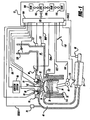
- Engine 10 comprising a plurality of cylinders, one cylinder of which is shown in Figure 1, is controlled by electronic engine controller 12.
- Engine 10 includes combustion chamber 30 and cylinder walls 32 with piston 36 positioned therein and connected to crankshaft 40.
- Combustion chamber 30 is shown communicating with intake manifold 44 and exhaust manifold 48 via respective intake valve 52 an exhaust valve 54.
- Each intake and exhaust valve is operated by an electromechanically controlled valve coil and armature assembly 53.
- Armature temperature is determined by temperature sensor 51.
- Valve position is determined by position sensor 50.
- each of valves actuators for valves 52 and 54 has a position sensor and a temperature sensor.
- Intake manifold 44 is also shown having fuel injector 66 coupled thereto for delivering liquid fuel in proportion to the pulse width of signal FPW from controller 12.
- Fuel is delivered to fuel injector 66 by fuel system (not shown) including a fuel tank, fuel pump, and fuel rail (not shown).
- fuel system including a fuel tank, fuel pump, and fuel rail (not shown).
- the engine may be configured such that the fuel is injected directly into the engine cylinder, which is known to those skilled in the art as direct injection.
- intake manifold 44 is shown communicating with optional electronic throttle 125.
- Distributorless ignition system 88 provides ignition spark to combustion chamber 30 via spark plug 92 in response to controller 12.
- Universal Exhaust Gas Oxygen (UEGO) sensor 76 is shown coupled to exhaust manifold 48 upstream of catalytic converter 70.
- UEGO Universal Exhaust Gas Oxygen
- Two-state exhaust gas oxygen sensor 98 is shown coupled to exhaust manifold 48 downstream of catalytic converter 70.
- sensor 98 can also be a UEGO sensor.
- Catalytic converter temperature is measured by temperature sensor 77, and/or estimated based on operating conditions such as engine speed, load, air temperature, engine temperature, and/or airflow, or combinations thereof.
- Converter 70 can include multiple catalyst bricks, in one example. In another example, multiple emission control devices, each with multiple bricks, can be used. Converter 70 can be a three-way type catalyst in one example.
- Controller 12 is shown in Figure 1 as a conventional microcomputer including: microprocessor unit 102, input/output ports 104, and read-only memory 106, random access memory 108, 110 keep alive memory, and a conventional data bus. Controller 12 is shown receiving various signals from sensors coupled to engine 10, in addition to those signals previously discussed, including: engine coolant temperature (ECT) from temperature sensor 112 coupled to cooling sleeve 114; a position sensor 119 coupled to a accelerator pedal; a measurement of engine manifold pressure (MAP) from pressure sensor 122 coupled to intake manifold 44; a measurement (ACT) of engine air amount temperature or manifold temperature from temperature sensor 117; and a engine position sensor from a Hall effect sensor 118 sensing crankshaft 40 position.
- engine position sensor 118 produces a predetermined number of equally spaced pulses every revolution of the crankshaft from which engine speed (RPM) can be determined.
- a direct injection type engine can be used where injector 66 is positioned in combustion chamber 30, either in the cylinder head similar to spark plug 92, or on the side of the combustion chamber.
- an engine can be configured with an array of electromechanical valve configurations.
- a plausible valve configuration may include electromechanical intake valves and mechanically actuated exhaust valves. This configuration provides flexible cylinder air amount control while reducing the cost that is associated with higher voltage valve actuators that can overcome exhaust gas pressure.
- Another conceivable mechanical/electrical valve configuration is electromechanical intake valves and variable mechanically driven exhaust valves (mechanically driven exhaust valves that can be controlled to adjust valve opening and closing events relative to a crankshaft location). This configuration may improve low speed torque and increase fuel economy at reduced complexity when compared to a full electromechanically actuated valve train.
- electromechanical intake and exhaust valves can provide greater flexibility but at a potentially higher system cost.
- Figure 2 is an example cylinder and valve mode selection method that can reduce complexity and yet is capable of flexibly controlling a variety of different valve configurations with few modifications.
- One example method described herein makes a set of cylinder and valve modes available each time the routine is executed. As the steps of the method are executed, different cylinder and valve modes may be removed from a set of available modes based on engine, valve, and vehicle operating conditions. However, the method may be reconfigured to initialize cylinder and valve modes in an unavailable state and then make desired cylinder and valve modes available as the different steps of the routine are executed. Thus, various options are available for the selection of an initialization state, order of execution, and activation and deactivation of available modes.
- step 1010 row and column cells of a matrix (mode matrix) representing valve and cylinder modes are initialized by inserting numerical 1's into all matrix row and column cells.
- a matrix (mode matrix) representing valve and cylinder modes are initialized by inserting numerical 1's into all matrix row and column cells.
- An example mode matrix is shown in Figure 3 for an eight cylinder engine having two banks of four-cylinders each in a V-type configuration.
- the mode matrix is a construct that holds binary ones or zeros in this example, although other constructs can be used.
- the matrix can represent cylinder and valve mode availability. In this example, the ones represent available modes while zeros represent unavailable modes.
- the mode matrix is initialized each time the routine is called, thereby making all modes initially available.
- Figures 7-13 illustrate some potential valve and cylinder modes, and are described in more detail below. Although a matrix is shown, it is possible to substitute other structures such as words, bytes, or arrays in place of the matrix.
- step 1012 some valve and/or cylinder modes that are affected by engine warm-up conditions are deactivated from the mode matrix. Operating conditions can be tested in Boolean logic statements and then cylinder and/or valve modes may be deactivated based on the results.
- warm-up valve and cylinder mode selection is based on engine operating conditions that determine an operating state of the engine. However, warm-up cylinder and valve mode selection determination based on operational conditions of an engine are not constrained to engine temperature and catalyst temperature.
- engine and catalyst temperature provide an indication of engine operating conditions
- conditions of an electromechanical valve can provide additional information and in some cases a basis for cylinder and valve mode changes.
- armature temperature determined by sensor 50 may be included into the above-mentioned representative condition that triggers a mode selection change.
- the number of valve operations, time since start, valve operating time, valve current, valve voltage, power consumed by the valve, valve impedance sensing devices, combinations thereof, and/or subcombinations thereof can augment (or supplant) the armature temperature sensor by providing additional operating conditions of a valve.
- operating conditions of an electromechanical valve can be used to determine the number of active cylinders and/or the number of strokes in the active cylinders, plus they can optionally be used to determine the number and configuration or pattern of operational valves.
- These valve operating conditions may be included with engine and catalyst conditions in the mode selection logic or they can comprise mode selection logic without engine and catalyst operating conditions.
- Selecting valve patterns may also be based on warm-up conditions, cylinder stroke mode, and number of active cylinders by the selection logic. This is accomplished by leaving desired valve patterns, cylinder stroke modes, and cylinder modes active given the selection logic. Then the remaining selection criteria of Figure 2 can determine the cylinder mode, number of active valves, active valve pattern, and cylinder stroke mode by applying the conditional constraints of steps 1014-1022 of Figure 2.
- electromechanical valves operation during the engine warm-up in this way can improve engine operation in a number of ways, such as, for example, by operating all cylinders of an engine with a fewer number of valves.
- One example of such an option would be a V8 with four electromagnetic valves per cylinder operated with eight cylinders and two valves per cylinder. Not only can such operation increase fuel economy (by saving electrical energy by reduced valve current), but engine noise, vibration, and harshness (NVH) can also be reduced since engine torque peaks are closer together. Further, valve power consumption at low temperature increases while power supply capacity may decrease.
- selecting a fewer number of valves during a low temperature condition(such as, for example, during an engine start) can make more current available to the engine starter so that longer engine cranking (rotating the engine until the engine is rotating under its own power) and higher cranking torque is possible without depleting battery capacity.
- the routine then proceeds to step 1014.
- step 1014 some valve and/or cylinder modes that affect engine emissions or that are affected by emissions are deactivated.
- the routine then continues to step 1016.
- step 1016 some valve and /or cylinder modes that are affected by engine operating region and valve degradation are deactivated. Catalyst and engine temperatures along with indications of valve degradation, are used in one example to determine cylinder and/or valve mode deactivation in this step. The description of Figure 5 provides further details of the selection process. The routine then continues to step 1018.
- step 1018 some valve and/or cylinder modes that affect engine and vehicle noise, vibration, and harshness (NVH) are deactivated.
- electromechanical valves can be selectively activated and deactivated to change the number of active cylinders and therefore the cylinder combustion frequency. It can be desirable, under selected circumstances, to avoid (or reduce) valve and cylinder modes that can excite vibrational frequencies or modes of a vehicle, i.e., frequencies where the mechanical structure has little or no damping characteristics. The valve and/or cylinder modes that affect these frequencies are deactivated in step 1018. The routine then proceeds to step 1020.
- step 1020 some cylinder and /or valve modes that do not provide sufficient torque to produce the desired engine brake torque are deactivated.
- desired engine brake torque is compared to the torque capacity of the cylinder and valve modes contained within the mode matrix. In one example, if the desired brake torque is greater than the torque capacity (including a margin of error, if desired) of a given cylinder and valve mode, then the cylinder and/or valve mode is deactivated. The routine then continues to step 1022.
- step 1022 the mode matrix is evaluated and the cylinder and valve modes are determined.
- deactivated cylinder and valve operating modes have been made unavailable by writing zeros into the appropriate mode matrix cell row/column pair.
- the mode matrix is searched starting from the matrix origin (0,0) cell, row by row, to determine row and column pairs containing ones.
- the last matrix row/column containing a value of one determines the valve and cylinder mode. In this way, the design of the mode matrix and the selection process causes the fewest number of cylinders and valves to meet the control objectives.
- a cylinder and/or valve mode change is requested, that is, if the method of Figure 2 determines that a different cylinder and/or valve mode is appropriate since the last time the method of Figure 2 executed, then an indication of an impending mode change is indicated by setting the requested mode variable to a value indicative of the new cylinder and/or valve mode. After a predetermined interval, the target mode variable is set to the same value as the requested mode variable.
- the requested mode variable is used to provide an early indication to peripheral systems of an impending mode change so that those systems may take action before the actual mode change. The transmission is one example where such action is taken.
- the actual cylinder and/or valve mode change can be initiated by changing the target mode variable.
- the method may delay changing requested and target torque while adjusting fuel to suit the new cylinder and/or valve mode by setting the MODE_DLY variable. Cylinder and/or valve mode changes are inhibited while the MODE_DLY variable is set.
- the chosen valve and cylinder mode is then output to the valve controller.
- the cylinder and valve mode selection routine is then exited.
- the cylinder and valve mode matrix structure can take alternate forms and have alternate objectives.
- an alternate embodiment might write numbers to the matrix that are weighted by torque capacity, emissions, and/or fuel economy.
- selection of the desired mode might be based on the values of the numbers written into the matrix cells.
- modes that define the axis of the matrix do not have to be in increasing or decreasing torque amounts; fuel economy, power consumption, audible noise, and emissions are a few additional criteria that may be used to define the structure of the mode control matrix organization.
- the matrix structure can be designed to determine cylinder and valve modes based on goals other than fewest cylinders and valves.
- the method of Figure 2 may be configured to determine operating conditions of a valve, valve actuator, engine, chassis, electrical system, catalyst system, or other vehicle system.
- the before-mentioned operating conditions may be used to determine a number of active cylinders, number of active valves, valve patterns, cylinder strokes in a cylinder cycle, cylinder grouping, alternate valve patterns, and valve phasing desired. Determining a variety of operating conditions and selecting an appropriate cylinder and valve configuration may improve engine performance, fuel economy, and customer satisfaction.
- At least the following two degrees of freedom can be used to regulate torque capacity of an engine:
- the method of Figure 2 can switch between cylinder and valve modes during a cycle of the engine based on engine operating conditions.
- an eight-cylinder engine operates four-cylinders in four-stroke mode and four-cylinders in twelve-stroke mode, all cylinders using four valves in each cylinder.
- This mode may generate the desired torque and a level of increased fuel efficiency by reducing the number of active cylinders and by operating the active cylinders at a higher thermal efficiency.
- the controller might switch the engine operating mode to four-cylinders operating in a four-stroke mode and using two valves in each cylinder. The remaining four-cylinders might operate in twelve-stroke mode with alternating exhaust valves.
- a cycle of an engine is defined herein as the number of angular degrees over which the longest cylinder cycle repeats.
- the cycle of a cylinder can be individually identified for each cylinder.
- a cycle of the engine is defined by the six-stroke cylinder mode, i.e., 1080 angular degrees.
- the cylinder and valve mode selection method described by Figure 2 may also be used in conjunction with a fuel control method to further improve engine emissions.
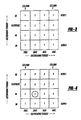
- FIG. 3 an example of an initialized cylinder and valve mode matrix for a V8 engine with electromechanical intake and exhaust valves is shown.
- the x-axis columns represent a few of potentially many valve modes for a cylinder with four valves.
- Dual intake/dual exhaust (DIDE), dual intake/alternating exhaust (DIAE), alternating intake/dual exhaust (AIDE), and alternating intake/alternating exhaust (AIAE) are shown from left to right, from higher to lower torque capacity.
- the y-axis rows represent a few of potentially many cylinder modes for a V8 engine.
- the cylinder modes with more cylinders begin at the bottom and end at the top with fewer cylinders, from higher to lower torque capacity.
- the mode matrix is advantageously constructed to reduce search time and mode interpretation.
- the intersection of a row and column, a cell identifies a unique cylinder and valve mode.
- cell (1,1) of the mode matrix in Figure 4 represents V4 cylinder mode and dual intake/alternating exhaust (DIAE) valve mode.
- the mode matrix is organized so that engine torque capacity in the cylinder/valve mode decreases as the distance from the origin increases.
- the reduction in torque capacity is greater by row than by column because the number of active cylinders per engine cycle decreases as the row number increases, whereas the different valve modes reduce the engine torque by a fraction of a cylinder torque capacity.
- the mode matrix construction is based on valves and cylinders, it naturally allows cylinder and valve modes to be defined that determine the number of active cylinders and valves as well as the cylinder and valve configuration.
- the mode matrix can identify cylinder and valve configurations that group cylinders and that have unique numbers of operating valves and valve patterns.
- the mode matrix can be configured to provide half of active cylinders with two active valves and the other half of active cylinders with three active valves.
- the mode matrix supports selection of multi-stroke modes.
- Multistroke operation generally includes a combustion cycle of greater than a four stroke combustion cycle. As described herein, multistroke operation includes greater than four stroke combustion, and variation of the number of strokes in the combustion cycle, such as, for example, variation between four-stroke, six-stroke, and/or twelve-stroke.
- different cylinders may be made active for a single cylinder mode, e.g., in a four-cylinder engine I2 cylinder mode may be produced by cylinders 1-4 or 2-3, by defining and selecting from two unique matrix cells.
- Any of the cylinder and valve modes represented in the mode matrix can be deactivated with the exception of the cylinder and valve mode that is located in the (0,0) cell. Cell (0,0) is not deactivated so that at least one mode is available.
- FIG. 4 an example of a matrix that has been through the cylinder and valve mode selection process is shown.
- the figure shows the zeros in the matrix cells that were initially set to ones in the mode matrix initialization, step 1010.
- cylinder and valve modes of lesser torque capacity are also deactivated.
- cell (1,2) has the higher torque capacity of the cells containing zeros.
- cell (1,1) is selected as the current cylinder and valve mode, i.e., V4-dual intake/alternating exhaust (DIAE). This can reduce search time of the matrix if searching ceases after a zero is encountered in the matrix.
- V4-dual intake/alternating exhaust V4-dual intake/alternating exhaust
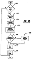
- FIG. 5 a flowchart of a method to deactivate cylinder modes (from available modes, for example) based on engine and valve operational limits is shown.
- the method evaluates engine and catalyst temperatures to determine which available cylinder and valve modes should be deactivated. Further, if valve degradation is indicated the method deactivates cylinder and valve modes influenced by the degradation, with the exception of the cylinder and valve mode in cell (0,0) of the mode matrix, if desired.
- step 1510 engine operating conditions are determined.
- Engine temperature sensor 112 and catalyst brick temperature 77 are measured.
- the temperatures may be inferred.
- exhaust valve temperature can be inferred from empirical data based on engine temperature, exhaust residuals, engine speed, engine air amount, and spark advance. The routine then proceeds to step 1512.
- step 1512 catalyst temperature, CAT_TEMP, is compared to a predetermined variable CAT_tlim. If the catalyst temperature is greater than CAT_tlim the routine proceeds to step 1514. If catalyst temperature is less than CAT_tlim then the routine proceeds to step 1516.
- step 1514 cylinder and valve modes are deactivated based on predetermined matrix, CAT_LIM_MTX.
- the matrix has the same dimension as the mode matrix, i.e., the matrices have the same number of elements.
- the cylinder and valve modes that produce higher temperatures are deactivated.
- the deactivated modes are then copied from the CAT_LIM_MTX to the mode matrix. For example, if a measured or inferred catalyst temperature is higher than desired for a V8 engine, partial cylinder modes, V4, six-stroke, and V2 are deactivated. Deactivating the partial cylinder modes lowers exhaust temperatures by decreasing the load per cylinder at the same desired torque.
- the routine then proceeds to step 1516.
- step 1516 engine temperature, ENG_TEMP, is compared to a predetermined variable ENG_tlim. If the engine temperature is greater than ENG_tlim the routine proceeds to step 1518. If the engine temperature is less than ENG_tlim then the routine proceeds to step 1520.
- step 1518 cylinder and valve modes are deactivated based on predetermined matrix, ENG_LIM_MTX, where the matrix has the same dimension as the mode matrix, i.e., the matrices have the same number of elements.
- ENG_LIM_MTX the matrix has the same dimension as the mode matrix, i.e., the matrices have the same number of elements.
- the deactivated modes are then copied from the ENG_LIM_MTX to the mode matrix. For example, if a measured or inferred catalyst temperature is higher than desired for a V8 engine, partial cylinder modes, V4, six-stroke, and V2 are deactivated. Deactivating the partial cylinder modes can lower exhaust temperatures by decreasing the load per cylinder at the same desired torque.
- the routine then proceeds to step 1520.
- step 1520 the inferred exhaust valve temperature, EXH_vlv_tmp, is to a predetermined variable EXH_tlim. If the inferred exhaust valve temperature is greater than EXH_tlim the routine proceeds to step 1522. If the inferred exhaust valve temperature is less than the EXH_tlim then the routine proceeds to step 1524.
- step 1522 cylinder and valve modes are deactivated based on predetermined matrix, EXH_LIM_MTX, where the matrix has the same dimension as the mode matrix, i.e., the matrices have the same number of elements.
- EXH_LIM_MTX the matrix has the same dimension as the mode matrix, i.e., the matrices have the same number of elements.
- the deactivated modes are then copied from the ENG_LIM_MTX to the mode matrix. For example, if a measured or inferred exhaust valve temperature is higher than desired for a V8 engine, partial cylinder modes, V4, six-stroke, and V2 are deactivated and the exhaust valves operate in an alternating mode. Deactivating the partial cylinder modes lowers exhaust temperatures by decreasing the load per cylinder while alternating valves facilitates heat transfer between the inactive exhaust valve and the cylinder head. The routine then proceeds to step 1524.
- valve degradation is evaluated.
- the valve degradation can be indicated in a number of ways that may include but are not limited to: valve position measurements, temperature measurements, current measurements, voltage measurements, by inference from oxygen sensors, or by an engine speed sensor. If valve degradation is detected, a variable, VLV_DEG, is loaded with the number of cylinders with degraded valves and a cylinder identifier, CYL_DEG, is loaded with the latest cylinder number where the degraded valve is located, in step 1528. If valve degradation is present, the routine continues to step 1526. If valve degradation is not indicated the routine exits.
- cylinder and valve modes that are affected by valve degradation are deactivated, which can include deactivating the cylinder(s) with the degraded valve(s).
- the cylinder in which the degraded valve is located, CYL_DEG is an index into a matrix, FN_DEGMODES_MTX, that contains cylinder modes that are affected by the cylinder that contains the degraded valve.
- the routine then deactivates the cylinder modes that are identified by the FN_DEGMODES_MTX.
- the cylinder mode of row zero is not deactivated so that the engine is capable of delivering torque from at least some (or all) cylinders with non-degraded valves when requested.
- VLV_DEG if more than one cylinder has degraded performance due to degraded valve performance, i.e., VLV_DEG is greater than one, the cylinder mode corresponding to row zero is the single active cylinder mode.
- affected cylinder modes may include disabling combustion, fuel injection, and/or ignition plug activation in the cylinders with degraded valves.
- fuel and/or spark can be deactivated in cylinders with degraded valve performance.
- Valve performance degradation may also be compensated in step 1526.
- Valve temperature is sensed by temperature sensor 50, but additional valve operating conditions may be determined as well. For example, valve voltage, impedance, and power consumption may be sensed or inferred. These parameters may be compared to predetermined target amounts to form error amounts that are then used to adjust an operating parameter of a vehicle electrical system. For example, if ambient air temperature increases and a voltage amount, measured or inferred, at a valve is lower than desired, a signal may be sent to the vehicle electrical system to increase the supply voltage. In this way, operating conditions of the valve may be used to adjust an operating condition of a vehicle electrical system so that valve operation is improved. The routine then proceeds to step 1530.
- step 1530 operating conditions of a vehicle electrical system are assessed. If electrical system available power, available current, and/or available voltage is below a predetermined amount or is degraded, the routine proceeds to step 1532. Furthermore, if an external electrical load, e.g., a computer or video game powered by the vehicle electrical system, or an ancillary, lower priority electrical load, e.g., a vehicle component, such as an air pump or fan, is loading the vehicle electrical system more than a predetermined amount or more than a fraction of the total available electrical system capacity, the routine proceeds to step 1532. The routine then proceeds to exit.
- an external electrical load e.g., a computer or video game powered by the vehicle electrical system
- an ancillary, lower priority electrical load e.g., a vehicle component, such as an air pump or fan
- step 1532 cylinder and valve modes are deactivated based on electrical system operating conditions. Copying zeros from selected matrices into the mode matrix deactivates cylinder and valve modes. If electrical system available power, available current, and/or available voltage are below a first set of predetermined amounts, matrix FNVLVRED zeros are copied into the mode matrix. In this example, the zeros restrict valve operation to the number of engine cylinders with two operational valves per cylinder. If the above-mentioned electrical parameters are below a second set of predetermined amounts, matrix FNCYLRED zeros are copied into the mode matrix. In this example, the zeros restrict valve operation to a reduced number of active cylinders and a reduced number of valves in active cylinders.
- a power switch e.g., a relay or transistor
- deactivates power to these devices if power to external or ancillary loads exceeds predetermined amounts, controlling a power switch, e.g., a relay or transistor, deactivates power to these devices.
- the combination of deactivating cylinder and valve modes along with reducing the affect of external and ancillary electrical loads can improve likelihood of starting during conditions of reduced electrical system capacity. For example, during cold ambient temperatures, engine friction increases and battery power may be reduced.
- deactivating lower priority electrical loads and selecting a reduced number of active cylinders and valves additional electrical power is available for an engine starter and active valves during starting.
- vehicle range may be increased if electrical system performance degrades during engine operation by deactivating lower priority electrical loads and reducing active cylinders and valves.
- a method to select a cylinder and valve mode from a matrix of available cylinder and valve modes is described.
- the method searches the entire mode matrix for a mode with the least number of active cylinders and valves. Since the before-mentioned steps have already deactivated cylinder and valve modes based on operating conditions of the engine and vehicle, this step provides a second example criteria for selection of cylinder and valve modes, namely, fuel economy. By selecting the fewest number of active cylinders and valves, fuel economy is increased by improving cylinder efficiency and reducing electrical power consumption.
- alternative search schemes can be used by structuring the columns and rows of the matrix differently to emphasize other goals, or combinations of different goals.
- step 1810 row and column indexes are initialized each time the routine is executed and the routine stores the current row and column index if the mode matrix cell pointed to by the indexes contains a value of one. In this example, only one row and column index is stored at a time. The routine proceeds to step 1812 after the current mode matrix cell is evaluated.
- step 1812 the current column number, cols, is compared to the number of columns of the mode matrix, col_lim. If the currently indexed column is less than the total number of mode matrix columns the routine proceeds to step 1814. If the indexed column is not less than the total number of mode matrix columns the routine proceeds to step 1816.
- step 1814 the column index value is incremented. This allows the routine to search from column zero to column col_lim of each row. The routine then continues to step 1810.
- step 1816 the column index is reset to zero. This action allows the routine to evaluate every column of every row of the mode matrix if desired. The routine then proceeds to step 1818.
- step 1818 the current row number, rows, is compared to the number of rows of the mode matrix, row_lim. If the currently indexed row is less than the total number of mode matrix rows the routine proceeds to step 1820. If the indexed row is not less than the total number of mode matrix rows the routine proceeds to step 1822.
- step 1820 the row index value is incremented. This allows the routine to search from row zero to column row_lim of each row. The routine then continues to step 1810.
- step 1822 the routine determines the desired cylinder and valve mode.
- the last row and column indexes are output to the torque determination routine, Figure 2, step 212.
- the row number corresponds to the desired cylinder mode and the column number corresponds to the desired valve mode.
- the routine then exits.
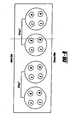
- the M label designates a mechanical valve operated by a camshaft (optionally having hydraulically actuated variable cam timing) while the E designates an electromechanical valve.
- the figure shows two cylinder groups, one group with electromechanically actuated intake valves and the other group with mechanically actuated intake valves. It is also possible to configure group two with mechanical intake valves and electromechanical exhaust valves. Yet another configuration may be where one group of cylinders has one or more electromechanically actuated valves and the remaining valves in the engine are mechanically activated. This allows the cylinder groups to have different valve configurations for different objectives.
- one cylinder group may operate with four valves while the other group operates with two valves. This allows the four valve cylinders to have a higher torque capacity during some conditions, such as speed and load conditions, and allows the engine to have multiple torque capacity amounts by selectively activating the electromechanically actuated valves.
- a V10 engine with two cylinder banks can be configured with a mechanically actuated valve bank and either an electromechanically actuated or combination mechanical/electromechanically actuated valve bank. Cylinders in the electromechanical bank may be deactivated as desired without the cost of installing electromechanical valves in all cylinders.
- engine emissions may be improved in an exhaust configuration where catalyst bricks are located at different distances from cylinder heads.
- a bank of cylinders with electromechanically actuated valves can retard exhaust valve timing, thereby increasing heat for the cylinder bank where the catalyst bricks are located further away from the cylinder head. Consequently, the different cylinder banks can be configured based on engine design to improve emissions.
- FIG. 7A an alternative configuration is shown with electrically actuated intake valves, and mechanically cam actuated exhaust valves (optionally with hydraulically actuated variable cam timing). Note that while two intake and two exhaust valves are shown, in yet another alternative embodiment, one electrically actuated intake, and one cam actuated exhaust valve can be used. Further, two electrically actuated intake valves, and one cam actuated exhaust valve can also be used.
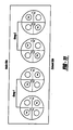
- FIG 8 an alternative grouped cylinder and valve configuration is shown.
- the configuration of Figure 8 offers some of the same benefits as those described for Figure 7, but all cylinders are shown with mechanical and electromechanically actuated valves.
- This configuration offers further control flexibility by allowing all cylinders to be mechanically controlled or by operating a mechanical group and a mechanical/electromechanical group. Placing the electromechanical valves and mechanical valves in different locations in the different cylinder groups can further alter this embodiment. For example, group one could be configured with electromechanical intake valves and mechanical exhaust valves while group two is configured with mechanical intake valves and electromechanical exhaust valves.
- the cylinder and valve configurations of Figures 7, 7A, and 8 may be further altered by changing electromechanical valve locations for mechanical valve locations or by rearranging valve patterns.
- one cylinder group arrangement may configure electromechanical intake and exhaust valves into a diagonal configuration that promotes cylinder charge swirl instead of the illustrated opposed valve configuration.
- valve locations designated by an S are operated during a cycle of the engine.
- additional valves may be mechanically operated by a cam, in some examples.
- the cylinder and valve configurations shown divide the cylinder into two regions (between intake and exhaust valves in Figure 9, and between groups of intake and exhaust valves in Figure 10).
- additional configurations can be used where the selected valve is in the same region but is not selected in the figure. These configurations can have at least some of the same benefits as the configurations as those described for Figures 7-8, for example.
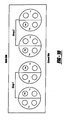
- FIG. 11 yet further embodiments of grouped cylinder and valve configurations are shown.
- the valve locations designated by an S the selected valve, are operated during a cycle of the engine.
- the cylinder and valve configurations shown break the cylinder into four regions, each region having an electromagnetically actuated valve, regions 1 and 2 containing intake valves, and regions 3 and 4 containing exhaust valves.
- additional configurations can be used where the selected valve is in an alternate region but is not selected in the figure.
- These configurations can have the same benefits as the configurations described for Figures 7-10, but the configurations can also offer more control flexibility.
- the selected valve patterns can be altered to provide 2, 3, and 4 valve operation.
- FIG. 14 illustrates a method to improve engine starting by controlling intake and exhaust valves.
- electromechanically actuated valves allow the ability to select the first cylinder to carry out combustion during a start.
- a consistent cylinder is selected for performing the first combustion, which can provide reduced emissions.
- variation in the amount of fuel delivered into each cylinder during a start can be decreased.
- unique fuel amounts can be repeatedly delivered into each cylinder. This is possible because fuel may be scheduled from the same reference point, i.e., the first cylinder selected to combust an air-fuel mixture.
- no two cylinders have identical intake ports in a multi cylinder engine.
- each cylinder has a unique fuel requirement to produce a desired in cylinder air-fuel mixture.
- one example of the method described herein allows fuel injected into each individual cylinder to be tailored to each unique port geometry, port surface finish, and injector spray impact location, thereby, reducing air-fuel variation and engine emissions.
- the cylinder selected for repeatedly carrying out the first combustion is varied. It can be varied based on various sets of operating conditions, such as a fixed number of starts, engine temperature, a combination thereof, or others.
- cylinder 1 is repeatedly used to start the engine.
- another cylinder e.g. a first available cylinder, or the same cylinder such as cylinder number 2
- a different cylinder is selected based on engine or air temperature.
- different cylinders for starting are selected based on barometric pressure (measured or estimated, or correlated to other parameters that are measured or estimated).
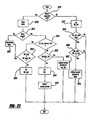
- step 3210 the routine determines if a request to start the engine has been made.
- a request may be made by an ignition switch, a remotely transmitted signal, or by another subsystem, e.g., a voltage controller of a hybrid power system. If not, the routine exits. If so, the routine proceeds to step 3212.
- step 3212 all exhaust valves are closed.
- the valves may be simultaneously closed or may be closed in another order to reduce power supply current.
- less than all of the exhaust valves can be closed.
- the closed valves remain closed until a combustion event has occurred in the respective cylinder of the valves. That is, the exhaust valve for a cylinder remains closed until a first combustion event has occurred in the cylinder.
- By closing the exhaust valve residual hydrocarbons can be prevented from exiting the cylinder during engine cranking and run-up (a period between cranking and before achieving a substantially stable idle speed). This can reduce emitted hydrocarbons and thereby can reduce vehicle emissions.
- the routine then proceeds to step 3214.
- intake valves may be set to a predetermined position, open or closed. Closing intake valves during cranking increases pumping work and starter motor current, but can trap hydrocarbons in a cylinder. Opening intake valves during cranking decreases pumping work and starter motor current, but may push hydrocarbons into the intake manifold.
- various combinations of open and closed intake valves can be used for example.
- closed intake valves are used.
- open intake valves are used.
- all exhaust valves may be set to an open position and the intake valves set to a closed position until engine position is established. Then exhaust valves in respective cylinders are closed at bottom-dead-center of piston travel and intake valves are operated based on a desired combustion order. The exhaust valves are operated after a first combustion event in the respective cylinders based on the desired engine cycle. Hydrocarbons are pumped out of a cylinder and then drawn back into the cylinder, being combusted in a subsequent cylinder cycle by this method. This can reduce emitted hydrocarbons when compared to mechanical four-stroke valve timing.
- step 3214 the engine is rotated and engine position is determined by evaluating the engine position sensor 118.
- a sensor that can quickly identify engine position can be used to reduce engine crank time and is therefore preferred. The routine then proceeds to step 3216.
- step 3216 engine indicated torque, spark advance and fuel are determined by calculating a desired indicated torque, calculating a desired fuel charge from the desired indicated torque, calculating a desired cylinder air charge from the desired fuel charge, determining valve timing from the desired air charge and determining the final spark from the desired cylinder air charge.
- valve timing and/or lift By adjusting the valve timing and/or lift to meet torque and air amount requirements during cranking and/or starting, the engine can be made to uniformly accelerate up to idle speed, start after start, whether at sea level or altitude.
- Figures 17 and 18 show example valve timing for producing uniform sea level and altitude engine starts.
- the method of Figure 14 can reduce variation in the mass of air and fuel required to start an engine. Nearly the same torque can be produced (if desired) at altitude and sea level by adjusting valve timing, injecting an equal amount of fuel, and similar spark timing. Only small adjustments for altitude are made to compensate for fuel volatility and engine back pressure differences. The method continues on to step 3218.
- Providing uniform engine starting speeds can also be extended to engine strategies that are not based on engine torque.
- a predetermined target engine air amount may be scheduled based on a number of fueled cylinder events and/or engine operating conditions (e.g., engine temperature, ambient air temperature, desired torque amount, and barometric pressure).
- engine operating conditions e.g., engine temperature, ambient air temperature, desired torque amount, and barometric pressure.
- the ideal gas law and cylinder volume at intake valve closing timing are used to determine the valve timing and duration.
- fuel is injected based on the target engine air amount and is then combusted with the inducted air amount. Because the target engine air amount is uniform or nearly uniform between sea level and altitude, valve timing adjustments are made while the fuel amount remains nearly the same (e.g. within 10%).
- a target fuel amount based on the number of fueled cylinder events and/or engine operating conditions may also be used to start an engine.
- a cylinder air amount based on the target cylinder fuel amount is inducted by adjusting valve timing to achieve the desired air-fuel ratio.
- the desired air-fuel ratio e.g., rich, lean, or stoichiometric
- spark advance may be adjusted based on the cylinder air amount
- valve timing may be further adjusted based on ambient air temperature and pressure
- fuel may be directly injected or port injected using this starting method.
- step 3218 the routine determines if combustion will be initiated in a predefined cylinder or in a cylinder that can complete a first intake stroke (e.g. a first available cylinder for combustion). If combustion is selected in a predefined cylinder the cylinder number is selected from a table or function that may be indexed by an engine operating condition or engine characteristic.
- a cylinder to begin combustion By selecting a cylinder to begin combustion, and by selecting the first combusting cylinder based on engine operating conditions, (start after start if desired) engine emissions can be improved.
- cylinder number one may be selected to produce a first combustion event each time the engine is started at 20° Celsius.
- a different cylinder may be selected to produce a first combustion event, this cylinder may be selected each time the engine is started at 40° Celsius, or alternatively, a different cylinder may be selected depending on engine control objectives. Selecting a starting cylinder based on this strategy can reduce engine emissions. Specifically, fuel puddles are commonly created in intake ports of port fuel injection engines.
- the injected fuel can attach to the intake manifold walls after injection and the amount of fuel inducted can be influenced by intake manifold geometry, temperature, and fuel injector location. Since each cylinder can have a unique port geometry and injector location, different puddle masses can develop in different cylinders of the same engine. Further, fuel puddle mass and engine breathing characteristics may change between cylinders based on engine operating conditions. For example, cylinder number one of a four-cylinder engine may have a consistent fuel puddle at 20° Celsius, but the puddle mass of cylinder number four may be more consistent at 40° Celsius. This can occur because the fuel puddle may be affected by engine cooling passage locations (engine temperature), ambient air temperature, barometric pressure, and/or a characteristic of the engine (e.g., manifold geometry and injector location).
- the location and temperature of a catalyst may also be used to determine a first cylinder to combust.
- emissions can be reduced.
- a catalyst for example, in an eight cylinder, two bank engine, it may be beneficial to produce a first combustion event in cylinder number four (bank one) for one of the above-mentioned reasons.
- engine hardware characteristics may also influence selection of a first cylinder to combust.
- cylinder location relative to a motor mount, and/or oxygen sensor location may be factors at one set of engine operating conditions and may not be used as factors at a different set of engine operating conditions. This strategy may be used if a cylinder selected for a first combustion event reduces engine noise and vibration at a lower temperature, but another cylinder has improved characteristics at a different temperature.
- the amount of lost fuel fuel that is injected into a cold engine but not observed in exhaust gases due to fuel puddles and migration into the crankcase, can change each time a cylinder combusts due to cylinder ring expansion. Further, the amount of lost fuel in a specific cylinder may change depending on the engine operating conditions. Therefore, it can be beneficial to select one cylinder for a first combustion event based on one set of engine operating conditions, and to select a different cylinder for a first combustion event based on a second set of operating conditions. Then, individual fuel amounts can be delivered to individual cylinders, in the same order, starting with the first cylinder to combust, such that fuel amount variability may be reduced. Thus, the same fuel amount can be injected into the same cylinder that has nearly the same (such as within 1% , within 5%, or within 10%) puddle mass, start after start.
- a first cylinder to combust may be beneficial to select and/or change a first cylinder to combust, during a start, based on engine operating conditions and/or engine characteristics.
- combustion can also be started in multiple cylinders, if desired.
- crankshaft twist is a momentary angular offset between the crankshaft ends that may occur during a start due to engine acceleration.
- the first cylinder to fire inducts a high air charge in an effort to accelerate the engine from crank to run speed, thereby producing a large acceleration.
- the crankshaft may twist due to the force exerted on the crankshaft by the piston and the distance from the combusting cylinder to the load. Therefore, selecting a predetermined cylinder that is located closest to the engine load or that has more support, i.e., a location central to the engine block, can reduce engine vibration during a start. And, by selecting a cylinder to start an engine on that reduces vibration, customer satisfaction may be improved.
- selecting a predetermined cylinder closest to the flywheel in which to carry out a first combustion event may increase engine crank time given a conventional mechanically constrained valve train.
- an engine with electromechanical valves is not mechanically constrained.
- engine valve timing can be adjusted to create an intake stroke on the first cylinder, closest to the engine flywheel, where the piston is capable of producing a vacuum in the cylinder.
- this can be the cylinder closest to the flywheel with a downward moving piston where sufficient vacuum is created to pull the injected fuel into the cylinder, enabling an engine output to be produced. Subsequent combustion can then proceed based on conventional four-stroke valve timing.
- the routine after processing a signal indicative of an engine start (or engine position), the routine sets an intake stroke on the first cylinder with sufficient piston downward movement to produce an engine output (e.g., engine torque, or a desired cylinder charge). Once this is set, the remaining cylinders can have their respective valve timings positioned relative to the set intake stroke of said cylinder. Then, the first combustion can be carried out in the first cylinder with sufficient piston downward movement, and subsequent combustion can be carried out in the remaining cylinder based on the position valve timings in the selected firing order.
- an engine output e.g., engine torque, or a desired cylinder charge
- step 3222 If combustion in a predefined cylinder is not desired the routine proceeds to step 3220.
- step 3220 the routine determines which cylinder can capture or trap the desired cylinder air amount first.
- the position of a piston and its direction of motion, up (traveling toward the cylinder head) or down (traveling away from the cylinder head) can also factor into this determination, as indicated below in the description of Figure 29.
- starting time can be reduced.
- selecting a cylinder capable of a first combustion event may also reduce engine starting time.
- engine starting speed and emissions variability can be affected.
- the type of fuel injection can also affect the cylinder selection process. Port fueled engines rely on an intake stroke to induct fuel and air into a cylinder.
- selecting a cylinder for a first combustion event, for a port injected engine can be defined by a capacity of a cylinder to induct both air and fuel.
- direct injection engines inject fuel directly into the cylinder providing an opportunity to combust fuel with air that is trapped by closing the intake and exhaust valves.
- an intake cycle of the valves may not be necessary to facilitate combustion in a cylinder because air trapped in the cylinder can be mixed with fuel that is directly injected into the cylinder. Therefore, engine valve timing can be adjusted based on engine position to facilitate combustion in the first cylinder, nearest the flywheel, capable of capturing and compressing a desired air amount.
- cylinders In addition, engines commonly have two pistons that are in the same cylinder position, relative to one another. Combustion in the cylinders can be defined by selecting the appropriate valve timing for the respective cylinders. Since electromechanical valves can be operated without regard to crankshaft position, an engine control strategy can select which of the two cylinders will combust first by applying the appropriate valve timing. Therefore, in step 3220, the strategy selects a cylinder based on its ability to capture a desired cylinder air amount and then sets the appropriate valve timing between competing cylinders. For example, a four-cylinder engine with pistons in cylinders 1 and 4 in position to complete a first induction stroke, cylinder 1 is selected to produce a first combustion event.
- example criteria to select one of two cylinders competing for a first combustion event include cylinder position, starting noise and vibration, and cylinder air-fuel maldistribution.
- cylinder position For example, in a four-cylinder engine, cylinder number four is located closest to the engine flywheel. The crankshaft may experience less twist during a start if cylinder four fires before cylinder one. This may reduce engine noise and vibration during a start.
- a certain cylinder may be located closer to engine mounts. The proximity of a cylinder to engine mounts may also influence which cylinder to select for a first combustion event.
- manufacturing processes and/or design limitations may affect air-fuel distribution in cylinders of an engine. Selecting a cylinder based on engine characteristics may improve air-fuel control during a start. The routine continues on to step 3222.
- step 3222 fuel is injected based on engine position and desired torque, spark, and Lambda from step 3216 above.
- fuel can be injected on open or closed valves, delivered to all cylinders at the same time, or be delivered to individual cylinders in individual amounts.
- fuel is preferentially injected on an individual cylinder basis so that the fuel amount can be tailored to a cylinder event.
- the period of the cylinder event signal is the crank angle duration wherein a cycle of a cylinder repeats, in the case of a four-stroke cylinder cycle a cylinder event in degrees is: 720/number of engine cylinders.
- fuel is injected based on the number of fueled cylinder events and controlled individual cylinder air amounts are used to improve engine air-fuel control.
- engine starting can be improved.
- fuel delivery based on the number of cylinder events and individual cylinder air amounts can improve engine air-fuel control. Consequently, fueling based on fueled cylinder events and controlling individual cylinder air amounts can be used to lower engine emissions and to provide uniform engine run-up speed during starting.
- engine fuel requirements can be a function of the number of fueled cylinder events rather than solely based on time. Cylinder events can be associated with mechanical dimensions; time is a continuum, which lacks spatial dimensions and linkage to the physical engine. Therefore, engine fueling based on the number of fueled cylinder events can reduce the fuel variation associated with time based fueling.
- step 3222 the amount of fuel injected in step 3222 produces a lean mixture during cold starts. This can reduce hydrocarbons and catalyst light off time. However, the amount of fuel injected may also produce a stoichiometric or rich mixture.
- the routine proceeds to step 3224.
- step 3224 the valves are operated starting with setting the stroke (intake) of the cylinder selected to produce a first combustion event. Alternately, another stroke (exhaust, power, compression) may be set in the first cylinder selected to combust.
- another stroke exhaust, power, compression
- valves are sequenced based on a predetermined order of combustion, see Figures 15-16 and 24-28 for example.
- all cylinders are operated in a four-stroke mode to reduce engine emissions and catalyst light off time.
- multi-stroke or a fraction of the total cylinders may also be used during starting. The routine proceeds to exit.
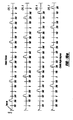
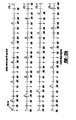
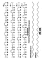
- Figures 15a and 15b are plots that show representative intake and exhaust valve timing at a relatively constant desired torque, spark, and Lambda for a four-cylinder engine operated in four-stroke mode by the method of Figure 14.
- Valve opening and closing positions are identified by a legend on the left side of the valve sequences, O for open and C for closed.
- electromechanically controlled intake and exhaust valves are set to a closed position from the deactivated mid position.
- intake valves may also be set to an open position in respective cylinders until the onset of a first intake event to reduce cranking torque and starter current.
- cylinder 1 is the cylinder selected for a first combustion event, but cylinder 3 or 2 may be selected if a quicker start is desired.
- exhaust valves are set to a closed position and remain in a closed position until a combustion event has occurred in the respective cylinder.
- the exhaust valves begin operation at the shown exhaust valve timing thereafter.
- cylinders with mechanical valve deactivators may deactivate exhaust or intake valves in a similar manner to produce similar results.
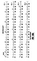
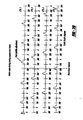
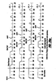
- Figures 16a and 16b are plots that show representative intake valve timing for two engine starts, at different engine positions, of a four-cylinder engine by the method of Figure 14. Cylinder 1 is selected as the starting cylinder and the engine is started at a substantially constant desired torque, spark, and Lambda (although in alternative examples, these can be variable). Valve opening and closing positions are identified by a legend on the left side of the valve sequences, O for open and C for closed.
- intake and exhaust valves are set to a closed position from the deactivated mid position.
- intake valves may also be set to an open position in respective cylinders until the onset of a first intake event to reduce cranking torque and starter current. From top to bottom, the first four valve timing events are for start #1, the second four valve timing events are for start #2, cylinder position is shown for start #1, and cylinder position is shown for start #2.
- the figure shows an engine stop position for start #1 that is approximately 50 degrees after top dead center of cylinders 1 and 4.
- the plot of cylinder 1 shows from piston position that the piston is already partially through its downward stroke motion. Key on occurs at this point, and fuel could be injected at this point on an open valve so that the mixture would then be compressed and combusted as the piston travels up in the following stroke.
- engine cranking speed at this point may be low because of engine inertia and friction which may lead to poor fuel atomization and combustion. Therefore, the engine controller, in this example, waits to open the intake valve until an entire intake stroke of cylinder 1 can be completed, roughly 280 engine crank angle degrees. The remaining cylinder valve events follow cylinder 1 in the combustion order illustrated.
- the first valve event of start #2 is approximately 180 degrees after key on. The valve event occurs earlier because the engine stop position permits a full intake stroke in cylinder #1 earlier than the engine stop position of start #1.
- Start #2 also shows how to align valve timing for a strategy that selects a cylinder for a first combustion event based on a cylinder that can complete a first full induction stroke.
- Cylinders 1 and 4 are the first cylinders capable of a full intake stroke because of the engine stop position.
- Pistons 2 and 3 are 180 degrees out of phase with pistons 1 and 4 and are therefore partially through a downward stroke in the engine stop position.
- Valve timing can be adjusted for direct injection (DI) engines using the same principles. For example, fuel is injected into a cylinder of a DI engine. Further, a cylinder that is selected for a first combustion event could also be based on piston position and direction of movement. Then the intake valve timing of the first cylinder can be adjusted to achieve a desired torque. However, fuel injection is not constrained in a DI by valve timing. Therefore, the desired engine air amount may be obtained by adjusting valve timing to open the intake valve before or after bottom dead center of an intake stroke.
- DI direct injection
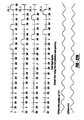
- Figures 17a and 17b are plots of representative intake valve timing during an engine start at sea level and a plot that shows representative intake valve timing during an engine start at altitude by the method of Figure 14.
- both starts begin at the same engine starting position and represent valve timing that follows a desired torque request that is used for both altitude and sea level. Substantially the same torque request is scheduled for altitude and sea level so that the fuel delivery remains nearly constant between altitude and sea level.
- different torque requests could also be used, if desired.
- a conventional engine adjusts the amount of fuel delivered based on an engine air amount, which differs between sea level and altitude due to variations in barometric pressure. This may result in different starting torque between sea level and altitude starts, resulting in different starting speeds between altitude and sea level. The change in engine speed and in the amount of fuel injected can then lead to air-fuel and emissions differences between sea level and altitude.
- valve timing As shown in Figure 17 so that engine torque and air amount is nearly the same between altitude and sea level (e.g., within 1%, 5%, or 10%), variation of air-fuel ratio and engine emissions between altitude and sea level are reduced. And while previous hydraulic VCT systems were able to adjust valve timing, these actuators typically were not functional during a start (since there was little to no hydraulic pressure available). Thus by using electric valves, improved starting can be obtained.
- the engine start #1 of Figure 17a is at sea level and begins with a longer valve event so that the engine will accelerate quickly from crank.
- the subsequent valve events are shorter as engine friction decreases and less torque is necessary to bring the engine up to idle speed.
- the valve duration remains substantially constant reflecting a substantially constant torque demand (although if torque demand changed, the durations could change, for example).
- the valve opening durations can begin to decrease after the first event.
- decreasing valve duration may be carried out over a fewer or greater number of cylinder events.
- the engine desired torque might change due to cold start spark retard or from combusting lean air-fuel mixtures.
- the engine start #2 is at altitude and begins with a longer valve event, when compared to the sea level valve event, so that the engine will accelerate at approximately the same rate from crank.
- the subsequent valve events are longer than the corresponding sea level valve events, but shorter than the initial valve event for the above-mentioned reasons.
- FIG. 18 a plot representative of cylinder #1 valve events at altitude and sea level along with representative desired torque request and engine speed trajectories is shown.
- the plot shows example engine starting differences between starting at sea level and altitude, while obtaining a uniform engine speed with little over-shoot that remains steady after idle speed is reached. Maintaining these engine speed and torque trajectories between altitude and sea level can reduce air-fuel variability and emissions. Further, the driver experiences more consistent engine performance during a start, and therefore customer satisfaction can be improved.
- valve timing can be adjusted for direct injection (DI) engines using the same principles.
- DI direct injection
- fuel can be injected into a cylinder of a DI engine based on piston position and direction of movement, after valve timing has been adjusted to achieve a desired torque at the present altitude.
- FIG. 19 a flowchart of a method to control valve timing after a request to stop an engine or to deactivate a cylinder is shown.
- step 3710 the routine determines if a request has been made to stop the engine or deactivate one or more cylinders.
- the request may be initiated by the driver of the vehicle or from within the vehicle control architecture, such as a hybrid-electric vehicle. If a request is present the routine proceeds to step 3712. If no request is present the routine proceeds to exit.
- step 3712 fuel is deactivated to individual cylinders based on the combustion order of the engine. That is, fuel injections that are in progress complete injection, and then fuel is deactivated. Further, calculations that determine the cylinder port fuel puddle mass continue and the intake valve duration is adjusted in step 3714 to produce the desired air-fuel ratio.
- Subsequent fuel puddle mass is obtained from: Where ⁇ m p is the fuel puddle mass entering a cylinder.
- ⁇ m p is the fuel puddle mass entering a cylinder.
- a predefined puddle mass or a puddle mass determined from a look-up table can be substituted for the puddle mass entering a cylinder.
- spark may be adjusted in this step based on the request to stop the engine.
- spark is adjusted to a value retarded from MBT to reduce engine hydrocarbons and increase exhaust heat.
- catalyst temperature may be increased so that if the engine is restarted sometime soon, higher catalyst conversion efficiency may be achieved, due to a higher catalyst temperature.
- retarding spark during engine shut-down may reduce evaporative emissions. Since hydrocarbon concentrations in exhaust gas may be reduced, exhaust gases that escape to the atmosphere during an engine stop may have fewer hydrocarbons.
- computer readable code can be used to retard ignition timing on at least one of a group of final combustion events during the shut-down to increase exhaust temperature thereby improving emissions on a subsequent engine re-start.
- one or several combustion events are still carried out, e.g., 1, 2, 3, 4, or a range of combustion events depending on operating conditions, e.g., 1-5, 1-3, 1-2, etc.
- By adjusting the ignition timing of at least some of these e.g., the last one, the last two, one of the last two or three
- adjusting of exhaust (or intake) valve opening and/or closing timing (or lift) can also be used (or alternatively used) to further increase exhaust gas heat to the catalyst during a shut-down.
- valve timing is adjusted.
- intake and exhaust valve timing can be adjusted.
- the intake valve opening (IVO) is moved to the engine position where a high intake port velocity is obtained, typically 45 degrees after the intake stroke begins. Moving the valve opening position to this location draws more fuel into the cylinder from the intake port puddle for a last combustion event. This can reduce the fuel puddle when the cylinder is deactivated or when the engine is stopped. Furthermore, a smaller fuel puddle contributes less fuel to a cylinder when the engine is restarted, thereby leading to more accurate air-fuel control during a start.
- the routine proceeds to step 3716.
- step 3716 fuel mass and valve opening location are used in conjunction with the ideal gas law to determine the valve opening duration and spark angle.
- the valves are operated with adjusted timing for at least an intake event, but may be operated longer if desired.
- the intake valve opening is typically adjusted to a location of between 30 and 180 crank angle degrees after top-dead-center of the intake stroke.
- the intake valve closing timing can also be adjusted to compensate air charge differences that may result from adjusting intake valve opening timing.
- the cylinder air-fuel mixture during engine shut-down may be lean, rich, or stoichiometric depending on control objectives.
- exhaust valves and spark advance may also be adjusted during engine shut-down.
- exhaust valves are adjusted to an opening location of between 0 and 120 crank angle degrees after top-dead-center of the exhaust stroke.
- additional heat can be added to the catalyst prior to engine shut-down. As mentioned above, this can increase catalyst temperature in anticipation of a subsequent start.
- exhaust valve closing timing can also be adjusted based on the adjusted exhaust valve opening time. The routine then exits.
- valve timing sequences begin on the left-hand side of the figure where the valve crank angle degrees are marked relative to top-dead-center of the combustion stroke of respective cylinders.
- the intake valves open at the end of the exhaust stroke indicating internal EGR flow into the cylinder.
- intake valve timing is adjusted for the first cylinder where fuel injection is deactivated after the shut down request, cylinder 1 in this example.
- Both the valve opening and valve duration are adjusted.
- the valve duration adjustment is based on an estimated fuel puddle fraction that enters the cylinder.
- the valve duration adjustment provides the desired exhaust air-fuel ratio.
- valve opening location can be adjusted along with scheduling a stoichiometric or lean final injection before deactivating fuel injection. Further, before fuel injection is deactivated, a specific number of injections can be scheduled coincident with the valve opening position adjustment.
- the figure illustrates three induction events after the valve timing adjustment is made. However, fewer or additional combustion or even non-combustion cylinder events after each intake event can be used.
- electromechanical valve actuators contain mechanical springs and electrical coils that act as electromagnets, both of which are used to regulate valve position.
- pressure in a cylinder may work for or against valve operation.
- exhaust valves overcome cylinder pressure to open, but are assisted by cylinder pressure when closing.
- capturing current, current necessary to overcome spring force, and holding current, current that holds a valve open or closed varies with operating conditions of the engine.
- the method described herein can restart a valve in and internal combustion engine if a predetermined current does not overcome an opening or closing spring force, permitting the valve to open or close during a cycle of the cylinder.
- the mechanical springs position valves in a mid position that is partially open.
- the valves can also assume the mid position if conditions in an engine do not permit the predetermined current to open or close the valve, i.e., the valve trajectory (position) deviates from a desired path. If the path of a valve deviates from the desired valve trajectory, one or more attempts may be made to restart the valve so that it can resume the desired trajectory.
- Valve trajectory may be determined directly from sensor measurements, sensor 50 for example, or by inference from crankshaft position.
- the variables of Figure 21 are arrays that contain data for each of the respective valves, although it can be applied to a subset of valves, or a single valve, if desired.
- valve trajectory is read from valve position sensor 51 and is evaluated to determine if an error in valve trajectory has occurred.
- Valve position sensor 51 may be a discrete or continuous position sensor. Desired valve position and current are determined by interrogating four matrices that contain look-up pointers for desired valve trajectories and associated currents. Matrices FNVLVCURO and FNVLVCURC hold numerical pointers that identify valve current vectors for valve opening and closing respectively. Matrices FNVLVPOSO and FNVLVPOSC hold numerical pointers that identify valve position for valve opening and closing respectively. Both the position and current matrices are indexed by engine speed and load.
- the pointers contained within the matrices then determine a specific vector that contains position or current information based on the valve position regions designated in Figure 22, CL_pos_set and CL_cur_set respectively.
- a separate valve control method accesses CL_cur_set to actuate the electromechanical valves. If an error in valve trajectory is determined the routine proceeds to step 3912. If no trajectory error is determined the routine proceeds to step 3932.
- predetermined current is applied to close the off-trajectory valve.
- the applied current is an upper current limit based on the valve and power supply.
- the valve may be moved to an open or mid position.
- fuel injection into the cylinder housing the off-trajectory valve may be disabled until the valve has completed a predetermined number of on-trajectory operations. The method proceeds to step 3914.
- step 3914 the routine determines if the off-trajectory valve has closed. If the valve has closed, the routine proceeds to step 3916. If the valve has not closed the routine proceeds to step 3930.
- steps 3912 and 3914 can be eliminated.
- valve current will be increased in the region where the trajectory error was detected.
- the valve will stay in a mid position until a command to open or close the valve is given based on the base valve timing.
- the current that drives the off-trajectory valve is increased in the region of the detected trajectory error, but the valve is restarted by the base valve timing, e.g., the valve timing based on desired torque and engine operating conditions.
- step 3930 deactivation of the off-trajectory valve and of the cylinder containing the valve occurs.
- the cylinder and valve are deactivated by the cylinder and valve mode selection method of Figure 2.
- the cylinder number containing the degraded valve is loaded into variable CYL_DEG during step 3930 and is passed to step 1528 of Figure 15. The routine then exits.
- valve current, CL_cur is compared against a predetermined variable, cur_lim.
- cur_lim a predetermined variable
- valve operation is resynchronized with engine timing.
- valve timing is aligned with the desired cycle of the respective cylinder.
- the resynchronization may be attempted after a predetermined number of cylinder cycles.
- step 3918 If the valve current is less than cur_lim the routine proceeds to step 3920.
- step 3918 the number of valve restart attempts at a current level of cur_lim, Rcl_dec, is compared to a predetermined variable, Rcl_deg_lim. If the number of restart attempts is greater than Rcl_deg_lim, the routine proceeds to step 3930. If the number of restart attempts is less than Rcl_deg_lim the routine proceeds to step 3924. This decision logic allows the routine to make a predetermined number of valve restart attempts before deactivating the cylinder and valve.
- step 3924 a count representing the number of valve restart attempts at the current amount in the cur_lim variable is incremented.
- the variable Rcl_deg is incremented. This variable allows the routine to deactivate the off-trajectory valve and the cylinder in which it resides to be deactivated if a predetermined number of attempts are exceeded, steps 3918 and 3930. The routine proceeds to exit after incrementing the variable.
- valve restart attempts are compared to a predetermined value.
- a variable, Rcl, representing the number of restart attempts at a current amount below cur_lim is compared to a predetermined value, Rcl_lim. If the number of restart attempts is greater than the predetermined value the routine proceeds to step 3922. If the number of restart attempts is less than the predetermined value the routine proceeds to step 3926.
- step 3926 a count representing a number of valve restart attempts below a current amount stored in Rcl_lim is incremented. After incrementing Rcl the routine proceeds to step 3928.
- valve current is adjusted.
- the before-mentioned valve control current vector, CL_cur_set is adjusted by a predetermined amount, ⁇ _adjust_up, each time a valve restart is attempted. Further, if a valve is restarted below the nominal engine operating temperature, CL_adjust is not adjusted, but valve current compensation based on temperature, Vt_adjust, is incremented by a predetermined amount at the temperature where the valve restart attempt is made.
- CL_cur_set current vector at the engine operating conditions
- Vt_adjust is a function that is indexed by engine or valve temperature
- CL_base_set is a vector containing base current amounts
- CL_adjust is a vector of adjustment current amounts at the engine operating conditions. Following the current adjustment the routine exits.
- valve current is set to a predetermined amount.
- CL_cur_set is set to cur_lim. This may allow a valve to restart sooner than by continuing to make small incremental current increases.
- a variable vector, Alow is loaded with the latest value of CL_cur_set. By loading CL_adjust into Alow the routine adapts the valve current based on engine operating conditions. The routine then proceeds to exit.
- step 3932 on-trajectory valve event counter is incremented.
- the number of on-trajectory valve events, openings and closings, Vlv_cnt, is incremented when no trajectory error is detected.
- the method may reduce valve current from the amount stored in cur_lim. The routine then proceeds to step 3934.
- valve current is compared to a predetermined amount. If the valve current is greater than the amount stored in cur_lim the routine proceeds to step 3936. If the valve current is less than the amount stored in cur_lim the routine exits.
- step 3936 the number of on-trajectory valve events, Vlv_cnt, is compared to a predetermined amount, Vlv_on_traj. If Vlv_cnt is greater than Vlv_on_traj the routine proceeds to step 3938. If Vlv_cnt is less than Vlv_on_traj the routine exits.
- valve current, CL_cur_set is adjusted to a lower amount. After a predetermined number of on-trajectory valve events the valve current is lowered by a predetermined amount, ⁇ _adjust_dn. By lowering the valve current after a predetermined number of on-trajectory events the routine can quickly restart valves and then locate a current amount that operates the valve while decreasing electrical losses and improving fuel economy. Therefore, step 3938 provides a current adapting operation for the routine. The routine then exits.
- valve trajectory regions during an opening and closing valve event is shown.
- valve trajectories during opening and closing events are compared to predefined valve trajectories such as those shown in Figure 22 to determine valve error trajectories.
- the valve trajectory is separated into seven regions, regions 1-4 describe valve opening and regions 4-7 describe valve closing.
- the valve restart method can increase or decrease valve current in specific regions. This allows the method of Figure 21 to adjust valve current in a desired region without increasing valve current in other regions, thereby improving engine and electrical efficiency.
- Valve current during valve opening and closing is also separated into regions, similar to those shown in Figure 22.
- Valve current in and around valve trajectory error regions can be adjusted to reestablish on-trajectory valve operation.
- valve trajectories and current amounts can be divided into a fewer or greater number of regions than shown in Figure 22.
- valve current is adjusted slowly and then steps up to CL_lim. Further, after the valve is restarted, the valve current is reduced in the direction of Alow.
- electromechanical valves may be used to improve engine starting and reduce engine emissions.
- Figures 24 through 28 present alternative valve sequences that may be used in engines with electromechanical valves or with valves that may be mechanically deactivated.
- the figures show four-cylinder operation for simplicity, but the methods can be carried over to engines with fewer or additional cylinders.
- any of the above operating modes can be used alone or in combination with one another, and/or in combination with varying the number of strokes of the cylinder cycle, phased intake, and/or phased exhaust valve opening and/or closing.
- plots show intake and exhaust valve timing during a start for an engine with mechanical exhaust valves and valves that may be held in an open position, electromechanical valves for example.
- the intake valves are set to an open position after a key on is observed.
- the starter rotates the engine
- the mechanically driven exhaust valves open and close based on the engine position and cam timing.
- the engine controller 12 determines engine position from crankshaft sensor 118.
- a delay time is shown between sync and the first valve operation (opening/closing), the actual delay may be shorter or longer.
- the intake valves are held open until before fuel is injected into an intake port of a cylinder selected for a first combustion event. Alternatively, the intake valve may be held open and fuel injected during a first intake stroke.
- Opening intake and exhaust valves during the same crank angle interval allows a portion of residual hydrocarbons to be pumped into the intake manifold where the hydrocarbons can be inducted and combusted after a first combustion event.
- the individual cylinder intake valves are held open until before fuel is injected into the ports of respective cylinders. After the valve is closed, fuel is injected, and then induction and four-stroke valve sequence begins.
- cylinders can be operated in multi-stroke modes and/or fuel may be injected on an open valve.
- fuel may be injected after the induction stroke on direct injection engines.
- plots show intake and exhaust valve timing during a start for an engine with valves that may be operated before combustion in a selected cylinder occurs, electromechanical valves for example.
- the intake valves are set to an open position after a key on is observed.
- the starter rotates the engine, the mechanically driven exhaust valves open and close based on the engine position and cam timing.
- the engine controller 12 determines engine position from crankshaft sensor 118. After engine position is known, the intake valves are closed when the exhaust valves are open, and the intake valves are held open when the exhaust valves are closed, until before fuel is injected into a intake port of a cylinder selected for a first combustion event.
- the intake valves are closed when the exhaust valves are open, and the intake valves are held open when the exhaust valves are closed.
- Fuel is injected on a closed intake valve prior to an induction event in respective cylinders.
- cylinders can be operated in multi-stroke modes and/or fuel may be injected on an open valve.
- fuel may be injected after the induction stroke on direct injection engines.
- plots show intake and exhaust valve timing during a start for an engine with valves that may be operated before combustion in a selected cylinder occurs, electromechanical valves for example.
- the intake valves are set to an open position after a key on is observed. As the starter rotates the engine the mechanically driven exhaust valves open and close based on the engine position and cam timing. At the vertical sync line, a point shown for illustration and that may vary depending on system configuration, the engine controller 12 determines engine position from crankshaft sensor 118. After engine position is known, the intake valves are open during crank angle intervals that can be intake and compression strokes of four-stroke cylinder operation. During crank angle intervals that can be considered power and exhaust strokes of four-stroke cylinder operation, the intake valves are closed. This sequence occurs until before fuel is injected into the intake port of a cylinder selected for a first combustion event.
- engine pumping work may be increased, but net residual hydrocarbon flow through the engine can be reduced. And, in some cases, net flow through the engine is reversed, such that gasses from the exhaust manifold are pumped into the intake manifold, before fuel injection is commenced.
- Fuel is injected on a closed intake valve prior to an induction event in respective cylinders.
- cylinders can be operated in multi-stroke modes and/or fuel may be injected on an open valve.
- fuel may be injected after the induction stroke on direct injection engines.
- plots show intake and exhaust valve timing during a start for an engine with valves that may be held in a position, electromechanical valves for example.
- the intake valves are set to an open position and the exhaust valves are set to a closed position after a key on is observed.
- the engine controller 12 determines engine position from crankshaft sensor 118. A delay time is shown between sync and the first valve operation (opening/closing), the actual delay may be shorter or longer.
- the intake valves are held open until before fuel is injected into the intake port of a cylinder selected for a first combustion event.
- intake valves By holding the intake valves in an open position and exhaust valves in a closed position, engine pumping work and residual hydrocarbons pumped through the engine as the engine rotates can be reduced. Opening intake valves can reduce engine pumping work since air can pass in and out of a cylinder as a piston travels toward or away from the cylinder head. Holding residual hydrocarbons in an engine and combusting the hydrocarbons may reduce the amount of hydrocarbons emitted into the exhaust since residual hydrocarbons may be converted into other constituents, namely CO 2 and H 2 O, during combustion.
- plots show intake and exhaust valve timing during a start for an engine with valves that may be held in a position, electromechanical valves for example.
- the intake valves are set to a closed position and the exhaust valves are set to an open position after a key on is observed.
- the engine controller 12 determines engine position from crankshaft sensor 118. A delay time is shown between sync and the first valve operation (opening/closing), the actual delay may be shorter or longer.
- the intake valve is held closed until fuel is injected into the intake port of the respective cylinder, and then the intake valve opens to induct an air-fuel mixture.
- exhaust valves are held in an open position until before a first induction event in the respective cylinder. After the exhaust valves are closed, exhaust valve operation is based on the operational stroke of the cylinder, four-stroke for example.
- valve timing may be set to produce a desired stroke in a selected cylinder.
- a piston that is traveling toward the cylinder head may be set to a compression or exhaust stroke by adjusting valve timing.
- setting the stroke of a cylinder can be described by Figure 29.
- a plot shows piston trajectories for two pistons in a four-cylinder engine over two engine revolutions.
- the piston trajectory of the top plot and the piston trajectory of the bottom plot are 180 crank angle degrees out of phase. That is, one piston is at the top of the cylinder while the other piston is at the bottom of a cylinder.
- Three symbols identify example engine positions where an engine controller may determine engine position during a start.
- four vertical lines pass through both plots to illustrate moveable decision boundaries where cylinder strokes can be determined.
- the number of decision boundaries can vary with the number of cylinders in an engine. Typically, one decision boundary is selected for every two cylinders in an engine.
- Setting the stroke (e.g., intake, combustion, compression, or exhaust) for a cylinder capable of a first combustion event may be accomplished based on a number of engine operating conditions, control objectives, and may include a decision boundary. For example, after engine position can be established, a decision boundary can be used as a location, over a crank angle interval, to set a stroke of a particular cylinder, based on engine operating conditions and control objectives.
- a four-cylinder engine with control objectives of a first combustion event in cylinder number one, producing a desired torque resulting from combustion event number one, could set the stroke of cylinder one, providing criteria are met, at or before a decision boundary.
- the remaining cylinder strokes can be set based on a predetermined order of combustion.
- the decision boundary can be described as a location in crankshaft degrees relative to a piston position.
- the decision boundary 1 is at approximately 170 degrees after top-dead-center of cylinder "B”.
- Decision boundary 2 is at approximately 350 degrees after top-dead-center of cylinder "B”.
- cylinder stroke for respective cylinders may be set by adjusting valve timing, before and up to, a boundary condition.
- Two boundary conditions, decision boundary 1 and decision boundary 2 are shown in Figure 29 because the illustrated cylinder trajectories are out of phase and the second boundary condition may be encountered, permitting setting of cylinder stroke, before the piston location represented by decision boundary 1 is reencountered.
- decision boundary 1 and 2 represent the same cylinder stroke setting opportunity, albeit in different cylinders.
- boundary conditions can move based on engine operating conditions and control objectives. For example, boundary conditions may be moved, relative to crankshaft angle, based on engine temperature or barometric pressure.
- engine operating parameters are evaluated to determine if the stroke of engine cylinders can be set. For example, if engine position and engine speed and/or acceleration permits induction of a desired air amount that can produce a desired engine output, a selected cylinder may be set to an induction stroke.
- desired engine outputs can include desired engine torque, a desired cylinder air amount, and a desired engine speed.
- the next boundary condition factors into setting the cylinder stroke.
- the "o" signifies a location where engine position might be established. If engine operating conditions meet criteria for setting the stroke of a cylinder before decision boundary 1 is encountered, the stroke of a selected cylinder can be set.
- cylinder “B” may be set to an intake stroke by adjusting valve timing such that cylinder “B” is the first cylinder to combust.
- the remaining cylinders are set to strokes based on a firing order, 1-3-4-2 in a four cylinder engine for example. In other words, if cylinder number one is set to an intake stroke, cylinder number three is set to an exhaust stroke, cylinder number four is set to a power stroke, and cylinder number two is set to a compression stroke.
- valve events may not follow four-stroke cylinder timings, up to a first combustion event, so that engine starting can be improved.
- the cylinder stroke cannot be set, the next stroke setting opportunity is at decision boundary 2.
- the "*" signifies another engine position where engine position might be established. Again, if engine operating conditions meet criteria for setting the stroke of a cylinder before decision boundary 1 is encountered, the stroke of the selected cylinder is set. However, the "*" position occurs closer to decision boundary than the " ⁇ " position. When engine position is determined closer to the decision boundary, opportunity to set the stroke of a cylinder can decrease. For example, if an engine is beginning to rotate and engine position is established near a decision boundary, there may not be a sufficient duration or sufficient upward or downward movement to induct a desired cylinder air amount and produce an engine output. In this example, setting the cylinder stroke may be delayed until the next decision boundary under these conditions.
- the " ⁇ " signifies yet another engine position where engine position might be established. In this position, if engine operating conditions meet criteria for setting the stroke of a cylinder before decision boundary 2 is encountered, the stroke of the selected cylinder is set. Specifically, in this case, cylinder "A" is set to an intake stroke and fueled to be the first cylinder to carry out combustion. Decision boundary 1 and 2 can be used to set the stroke of different cylinders that produce a first combustion event.
- valve timing of electromechanical valves, for example
- first combustion event or a first fuel injection event
- routines described in Figures 2, 5, 6, 14, 19, and 21 may represent one or more of any number of processing strategies such as event-driven, interrupt-driven, multi-tasking, multi-threading, and the like. As such, various steps or functions illustrated may be performed in the sequence illustrated, in parallel, or in some cases omitted. Likewise, the order of processing is not necessarily required to achieve the features and advantages described herein, but are provided for ease of illustration and description. Although not explicitly illustrated, one of ordinary skill in the art will recognize that one or more of the illustrated steps or functions may be repeatedly performed depending on the particular strategy being used.
- an approach can be used where the engine varies the number of cylinders carrying out combustion. Further, not only can the number of the cylinders carrying out combustion be varied, but the number of valves in active cylinders can also be varied (in time, or between different cylinder groups). Further still, in addition or as an alternative, the number of strokes in active cylinders can be varied (in time, or between different cylinder groups). Thus, in one example, in a first mode the engine can operate with a first number of cylinders carrying out combustion with a first number of strokes and a first number of active valves, and in a second mode, the engine can operate with a second number of cylinders carrying out combustion with a second number of strokes and a second number of active valves.
- a first group of cylinders of the engine can operate with a first number of strokes and a first number of active valves
- a second group of cylinders of the engine can operate with a second number of strokes and a second number of active valves.
- the cylinders can have equal number of valves active, yet different valve patterns (e.g., one group of cylinder can have the active intake valve and exhaust valve in a diagonal configuration, while another group has a non-diagonal configuration).
- control system can use a combination of varying the number of cylinders carrying out combustion, varying the number (or pattern) of active valves, and/or varying the number of strokes of active cylinders as ways to control engine output torque. By having numerous degrees of freedom, it can be possible to better optimize engine performance for various operating conditions.
- the present description provides for A method for reducing emissions of at least a cylinder of a multi-cylinder internal combustion engine with adjustable valve timing, the method comprising: retarding an intake valve opening position of said at least a cylinder in response to a request to stop said engine; adjusting an intake valve closing position of said at least a cylinder in response to said intake valve opening position; and operating said at least a cylinder for at least one intake stroke of said at least a cylinder after said valve opening and said valve closing position adjustments.
- the method also provides for adjusting the intake valve opening position to between 30 and 180 crank angle degrees after top-dead-center of the intake stroke of said cylinder, adjusting the spark timing of the cylinder in response to the request to stop, and for adjusting the timing of at least an exhaust valve in the cylinder, adjusting the exhaust valve closing position to between 0 and 120 crank angle degrees after top-dead-center of the exhaust stroke.
- the method provides for A method for reducing emissions of at least a cylinder of a multi-cylinder internal combustion engine with adjustable valve timing, the method comprising: retarding an intake valve opening position of at least a cylinder in response to a request to stop said engine; adjusting fuel injected to said at least a cylinder to produce a lean mixture in said at least a cylinder; and operating said at least a cylinder for at least one intake stroke of said at least a cylinder after said retarding of said intake valve opening position and said fuel adjustment.
- the method also provides for adjusting the timing of at least one exhaust valve in the cylinder, and adjusting the spark timing of the cylinder in response to the request to stop.
- the method provides for a method for reducing emissions of at least a cylinder of a multi-cylinder internal combustion engine with adjustable valve timing, the method comprising: retarding an intake valve opening position of said cylinder in response to a request to deactivate said cylinder; and operating said cylinder for at least one intake stroke of said cylinder after said valve opening position adjustment.
- the method also provides for adjusting spark timing in response to the deactivation request, adjusting the timing of an exhaust valve in the cylinder, and an electrically actuated intake valve.
- the number of strokes can be varied as a condition of a catalyst in the exhaust system varies, such as, for example, the amount of stored oxidants.
- other engine parameters can also be adjusted based on catalyst conditions, such as the number of active valves in active cylinders, and/or the pattern of active valve in active cylinders.
- the number of cylinders carrying out combustion can also be varied as catalyst conditions vary.
Applications Claiming Priority (2)
| Application Number | Priority Date | Filing Date | Title |
|---|---|---|---|
| US805648 | 2004-03-19 | ||
| US10/805,648 US7021289B2 (en) | 2004-03-19 | 2004-03-19 | Reducing engine emissions on an engine with electromechanical valves |
Publications (3)
| Publication Number | Publication Date |
|---|---|
| EP1577523A2 true EP1577523A2 (de) | 2005-09-21 |
| EP1577523A3 EP1577523A3 (de) | 2010-07-14 |
| EP1577523B1 EP1577523B1 (de) | 2019-06-26 |
Family
ID=34838963
Family Applications (1)
| Application Number | Title | Priority Date | Filing Date |
|---|---|---|---|
| EP05004579.8A Active EP1577523B1 (de) | 2004-03-19 | 2005-03-02 | Verminderung der abgasemissionen einer maschine mit elektromechanischen ventilen |
Country Status (4)
| Country | Link |
|---|---|
| US (6) | US7021289B2 (de) |
| EP (1) | EP1577523B1 (de) |
| JP (1) | JP2005264947A (de) |
| CN (1) | CN100520015C (de) |
Cited By (2)
| Publication number | Priority date | Publication date | Assignee | Title |
|---|---|---|---|---|
| EP1643120A2 (de) * | 2004-09-30 | 2006-04-05 | Walbro Engine Management, L.L.C. | Wegfahrsperresteuerschaltung für Brennkraftmaschine und Methode zu ihrem Betrieb |
| CN105179057A (zh) * | 2015-04-30 | 2015-12-23 | 牛刚学 | 发动机排气系统、气门供油排气综合控制系统及控制方法 |
Families Citing this family (66)
| Publication number | Priority date | Publication date | Assignee | Title |
|---|---|---|---|---|
| US7107947B2 (en) * | 2004-03-19 | 2006-09-19 | Ford Global Technologies, Llc | Multi-stroke cylinder operation in an internal combustion engine |
| US7559309B2 (en) * | 2004-03-19 | 2009-07-14 | Ford Global Technologies, Llc | Method to start electromechanical valves on an internal combustion engine |
| US7165391B2 (en) * | 2004-03-19 | 2007-01-23 | Ford Global Technologies, Llc | Method to reduce engine emissions for an engine capable of multi-stroke operation and having a catalyst |
| US7555896B2 (en) * | 2004-03-19 | 2009-07-07 | Ford Global Technologies, Llc | Cylinder deactivation for an internal combustion engine |
| US7383820B2 (en) * | 2004-03-19 | 2008-06-10 | Ford Global Technologies, Llc | Electromechanical valve timing during a start |
| US7021289B2 (en) * | 2004-03-19 | 2006-04-04 | Ford Global Technology, Llc | Reducing engine emissions on an engine with electromechanical valves |
| US7107946B2 (en) * | 2004-03-19 | 2006-09-19 | Ford Global Technologies, Llc | Electromechanically actuated valve control for an internal combustion engine |
| US7128043B2 (en) | 2004-03-19 | 2006-10-31 | Ford Global Technologies, Llc | Electromechanically actuated valve control based on a vehicle electrical system |
| US7128687B2 (en) * | 2004-03-19 | 2006-10-31 | Ford Global Technologies, Llc | Electromechanically actuated valve control for an internal combustion engine |
| US7194993B2 (en) * | 2004-03-19 | 2007-03-27 | Ford Global Technologies, Llc | Starting an engine with valves that may be deactivated |
| DE102005001047B4 (de) * | 2005-01-07 | 2018-08-16 | Volkswagen Ag | Verfahren zum Betrieb eines Hybridfahrzeugs sowie Hybridfahrzeug |
| DE102005001046B4 (de) * | 2005-01-07 | 2014-11-06 | Volkswagen Ag | Verfahren zum Betrieb eines Hybridfahrzeugs sowie Hybridfahrzeug mit einem mit einer Elektromaschine gekoppelten Mehrzylinderverbrennungsmotor |
| US8763582B2 (en) * | 2005-05-12 | 2014-07-01 | Ford Global Technologies, Llc | Engine starting for engine having adjustable valve operation and port fuel injection |
| US7469667B2 (en) * | 2005-07-07 | 2008-12-30 | Ford Global Technologies, Llc | Method for controlling a variable event valvetrain |
| US7296550B2 (en) | 2005-09-12 | 2007-11-20 | Ford Global Technologies, Llc | Starting an engine having a variable event valvetrain |
| US8528511B2 (en) | 2005-09-23 | 2013-09-10 | Jp Scope, Inc. | Variable travel valve apparatus for an internal combustion engine |
| US7373909B2 (en) * | 2005-09-23 | 2008-05-20 | Jp Scope Llc | Valve apparatus for an internal combustion engine |
| JP2007100660A (ja) * | 2005-10-07 | 2007-04-19 | Hitachi Ltd | 車両用エンジンの始動準備装置 |
| JP4832068B2 (ja) * | 2005-12-05 | 2011-12-07 | トヨタ自動車株式会社 | 空燃比制御装置 |
| US7174252B1 (en) | 2006-01-23 | 2007-02-06 | Ford Global Technologies, Llc | Method for reducing power consumption and emissions for an internal combustion engine having a variable event valvetrain |
| JP2007247476A (ja) * | 2006-03-14 | 2007-09-27 | Honda Motor Co Ltd | 内燃機関の制御装置 |
| US7562530B2 (en) * | 2006-04-05 | 2009-07-21 | Ford Global Technologies, Llc | Method for controlling an internal combustion engine having a variable event valvetrain |
| US7458346B2 (en) * | 2006-04-05 | 2008-12-02 | Ford Global Technologies, Llc | Method for controlling valves of an engine having a variable event valvetrain during an engine stop |
| US7621126B2 (en) * | 2006-04-05 | 2009-11-24 | Ford Global Technoloigies, LLC | Method for controlling cylinder air charge for a turbo charged engine having variable event valve actuators |
| US7417331B2 (en) * | 2006-05-08 | 2008-08-26 | Towertech Research Group, Inc. | Combustion engine driven electric generator apparatus |
| FR2904371B1 (fr) * | 2006-07-25 | 2012-08-31 | Valeo Sys Controle Moteur Sas | Dispositif de controle du fonctionnement d'un moteur associe a un actionneur electromagnetique de soupapes et un alternodemarreur |
| US20100047959A1 (en) * | 2006-08-07 | 2010-02-25 | Emcore Solar Power, Inc. | Epitaxial Lift Off on Film Mounted Inverted Metamorphic Multijunction Solar Cells |
| US20080078593A1 (en) * | 2006-09-29 | 2008-04-03 | Walt Ortmann | Hybrid Vehicle with Camless Valve Control |
| US7438042B1 (en) * | 2007-05-17 | 2008-10-21 | Mazda Motor Corporation | Method of stopping internal combustion engine |
| DE102007028854B4 (de) | 2007-06-22 | 2018-08-02 | Bayerische Motoren Werke Aktiengesellschaft | Verfahren zur Steuerung einer Brennkraftmaschine |
| JP5209454B2 (ja) * | 2008-12-09 | 2013-06-12 | 本田技研工業株式会社 | 内燃機関の停止時に点火を停止する時期を制御する装置 |
| DE102009035160B4 (de) * | 2009-03-31 | 2021-02-11 | Dr. Ing. H.C. F. Porsche Aktiengesellschaft | Verfahren zum Starten eines Verbrennungsmotors |
| US8667953B2 (en) * | 2009-10-14 | 2014-03-11 | GM Global Technology Operations LLC | Cylinder deactivation to reduce fuel enrichment after fuel cutoff modes |
| JP2011085078A (ja) * | 2009-10-16 | 2011-04-28 | Hitachi Automotive Systems Ltd | 内燃機関の制御装置及び内燃機関の制御システム |
| US8397693B2 (en) * | 2010-03-22 | 2013-03-19 | GM Global Technology Operations LLC | Engine including system and method for reducing oil pull-over in combustion chamber |
| CN102859138A (zh) * | 2010-04-26 | 2013-01-02 | 丰田自动车株式会社 | 内燃机 |
| US20130218439A1 (en) * | 2010-10-28 | 2013-08-22 | International Engine Intellectual Property Company, Llc | Controlling variable valve actuation system |
| US8843262B2 (en) * | 2010-12-22 | 2014-09-23 | Toyota Jidosha Kabushiki Kaisha | Vehicle, method for controlling vehicle, and device for controlling vehicle |
| US8798891B2 (en) * | 2011-07-06 | 2014-08-05 | GM Global Technology Operations LLC | System and method for increasing operating efficiency of a hybrid vehicle |
| WO2013080376A1 (ja) * | 2011-12-02 | 2013-06-06 | トヨタ自動車株式会社 | ハイブリッド車両 |
| US9447747B2 (en) * | 2012-05-04 | 2016-09-20 | Ford Global Technologies, Llc | Methods and systems for stopping an engine |
| US9567928B2 (en) * | 2012-08-07 | 2017-02-14 | GM Global Technology Operations LLC | System and method for controlling a variable valve actuation system to reduce delay associated with reactivating a cylinder |
| CN103266955B (zh) * | 2013-04-19 | 2017-02-22 | 牛刚学 | 多缸内燃机分缸工作的方法及装置 |
| US9512766B2 (en) | 2013-08-16 | 2016-12-06 | Ford Global Technologies, Llc | Multi-cell structure for automotive catalyst support |
| WO2015077359A1 (en) | 2013-11-21 | 2015-05-28 | Tula Technology, Inc. | System for managing catalytic converter temperature |
| US9581126B2 (en) * | 2013-12-17 | 2017-02-28 | Ford Global Technologies, Llc | Engine control for limiting catalyst temperature in normal and economy modes |
| US9752464B2 (en) * | 2014-05-28 | 2017-09-05 | Ford Global Technologies, Llc | Supercharged applied ignition internal combustion engine with exhaust-gas turbocharging and method for operating an internal combustion engine of said type |
| US9506408B2 (en) * | 2014-06-02 | 2016-11-29 | Ford Global Technologies, Llc | Method of fuel injection for a variable displacement engine |
| US9387849B2 (en) | 2014-06-19 | 2016-07-12 | Tula Technology, Inc. | Implementing skip fire with start/stop feature |
| AT516215B1 (de) * | 2014-09-03 | 2017-11-15 | Ge Jenbacher Gmbh & Co Og | Verfahren zum Starten einer Brennkraftmaschine |
| US11560818B2 (en) | 2015-11-11 | 2023-01-24 | Tula Technology, Inc. | Lean burn internal combustion engine exhaust gas control |
| US10823029B2 (en) | 2015-11-11 | 2020-11-03 | Tula Technology, Inc. | Determining firing density of a skip fire controlled lean-burn engine using air-fuel ratio and exhaust temperatures |
| US11053828B2 (en) | 2015-11-11 | 2021-07-06 | Tula Technology, Inc. | Separately determining firing density and pumping density during firing density transitions for a lean-burn internal combustion engine |
| CN108350818B (zh) | 2015-11-11 | 2022-01-21 | 图拉技术公司 | 稀燃内燃发动机排气温度控制 |
| DE102016209957A1 (de) * | 2016-06-07 | 2017-12-07 | Volkswagen Aktiengesellschaft | Verfahren zum Betreiben einer Brennkraftmaschine und Brennkraftmaschine |
| MX2019002668A (es) | 2016-09-09 | 2020-08-13 | Charles Price | Aparato de válvulas de desplazamiento variable para un motor de combustión interna. |
| US10232841B2 (en) * | 2016-11-18 | 2019-03-19 | Ford Global Technologies, Llc | Methods and system for improving response of a hybrid vehicle |
| WO2018102542A1 (en) * | 2016-11-30 | 2018-06-07 | Cummins Inc. | Compression release valvetrain design |
| US10107208B2 (en) * | 2017-01-03 | 2018-10-23 | Ford Global Technologies, Llc | System and method to operate an engine |
| DE102018117359A1 (de) * | 2017-12-04 | 2019-06-06 | Schaeffler Technologies AG & Co. KG | Verfahren zum Steuern eines Verbrennungsmotors |
| CN109372642A (zh) * | 2018-10-30 | 2019-02-22 | 潍柴动力股份有限公司 | 一种发动机快速熄火控制方法及装置 |
| JP6992730B2 (ja) * | 2018-11-13 | 2022-01-13 | 株式会社デンソー | 内燃機関の制御装置 |
| JP7047731B2 (ja) * | 2018-12-04 | 2022-04-05 | トヨタ自動車株式会社 | 内燃機関システム |
| CN110360044A (zh) * | 2019-06-28 | 2019-10-22 | 浙江吉利控股集团有限公司 | 一种起动机运转保护控制系统及其控制方法及汽车 |
| SE544230C2 (en) * | 2020-03-26 | 2022-03-08 | Scania Cv Ab | Method and arrangement for variable valve timing for inernal combustion engine; vehicle and engine with such arrangement; computer program and computer readable medium for such a method |
| JP7331808B2 (ja) * | 2020-08-28 | 2023-08-23 | トヨタ自動車株式会社 | 内燃機関の制御装置 |
Citations (1)
| Publication number | Priority date | Publication date | Assignee | Title |
|---|---|---|---|---|
| US5765514A (en) | 1995-01-27 | 1998-06-16 | Honda Giken Kogyo K.K. | Control system for internal combuston engines |
Family Cites Families (203)
| Publication number | Priority date | Publication date | Assignee | Title |
|---|---|---|---|---|
| DE2051220A1 (de) * | 1970-10-19 | 1972-04-20 | Robert Bosch Gmbh, 7000 Stuttgart | Steuerung von Ein- und Auslaßventilen bei Brennkraftmaschinen durch Flüssigkeit |
| DE2231630A1 (de) * | 1972-06-28 | 1974-01-17 | Volkswagenwerk Ag | Verfahren und einrichtung zur funktionspruefung eines elektromagnetischen ventils, insbesondere eines kraftstoff-einspritzventils |
| US4009695A (en) | 1972-11-14 | 1977-03-01 | Ule Louis A | Programmed valve system for internal combustion engine |
| US4129040A (en) | 1977-09-29 | 1978-12-12 | Hayden Jr Joseph C | Engine overspeed control system |
| SE450104B (sv) * | 1985-10-18 | 1987-06-09 | Spirac Engineering Ab | Anordning for komprimering av material och reduktion av dess vetskeinnehall |
| US4732117A (en) | 1986-07-02 | 1988-03-22 | Toyota Jidosha Kabushiki Kaisha | Two-cycle internal combustion engine |
| DE3633113A1 (de) * | 1986-09-30 | 1988-03-31 | Bosch Gmbh Robert | Verfahren und vorrichtung zur automatischen erfassung der ansprechspannung eines elektromagnetischen bauteils, insbesondere eines magnetventils |
| EP0264706B1 (de) * | 1986-10-13 | 1990-10-24 | Audi Ag | Verfahren zum Betrieb einer Brennkraftmaschine |
| JPS63124839A (ja) * | 1986-11-12 | 1988-05-28 | Honda Motor Co Ltd | 空燃比設定方法 |
| JPS63167016A (ja) | 1986-12-27 | 1988-07-11 | Honda Motor Co Ltd | 多気筒内燃機関の動弁装置 |
| US4807495A (en) | 1988-05-23 | 1989-02-28 | General Electronic Company | Temperature-dependent infinitely variable ratio transmission control system and method |
| US5123397A (en) | 1988-07-29 | 1992-06-23 | North American Philips Corporation | Vehicle management computer |
| US4945870A (en) | 1988-07-29 | 1990-08-07 | Magnavox Government And Industrial Electronics Company | Vehicle management computer |
| JPH0715270B2 (ja) | 1988-08-08 | 1995-02-22 | 日産自動車株式会社 | パワートレーンの総合制御装置 |
| US4965741A (en) * | 1988-10-17 | 1990-10-23 | Ncr Corporation | Method for providing an improved human user interface to a knowledge based system |
| JPH02123212A (ja) | 1988-10-31 | 1990-05-10 | Isuzu Motors Ltd | バルブ制御装置 |
| US5072702A (en) | 1989-06-29 | 1991-12-17 | Fuji Jukogyo Kabushiki Kaisha | Engine shut-down device |
| US4962741A (en) | 1989-07-14 | 1990-10-16 | Ford Motor Company | Individual cylinder air/fuel ratio feedback control system |
| JP3043349B2 (ja) | 1989-12-12 | 2000-05-22 | 株式会社いすゞセラミックス研究所 | 電磁力バルブ駆動制御装置 |
| JP2709742B2 (ja) | 1989-12-20 | 1998-02-04 | 株式会社いすゞセラミックス研究所 | 電磁力バルブ駆動装置 |
| US5117790A (en) * | 1991-02-19 | 1992-06-02 | Caterpillar Inc. | Engine operation using fully flexible valve and injection events |
| US5219397A (en) | 1991-04-02 | 1993-06-15 | Globe-Union Inc. | Reduced starting load system for an automobile engine |
| US5280770A (en) * | 1991-06-26 | 1994-01-25 | Honda Giken Kogyo Kabushiki Kaisha | Variable valve actuation control system |
| JP2642009B2 (ja) * | 1991-09-18 | 1997-08-20 | 本田技研工業株式会社 | エンジンの制御方法 |
| DE4140586C2 (de) * | 1991-12-10 | 1995-12-21 | Clark Equipment Co N D Ges D S | Verfahren und Steuereinrichtung zur Steuerung des Stroms durch eine Magnetspule |
| US5190013A (en) * | 1992-01-10 | 1993-03-02 | Siemens Automotive L.P. | Engine intake valve selective deactivation system and method |
| JP2697458B2 (ja) * | 1992-02-28 | 1998-01-14 | 三菱自動車工業株式会社 | エンジンの点火時期制御装置 |
| JPH05272367A (ja) | 1992-03-26 | 1993-10-19 | Mitsubishi Motors Corp | 休筒エンジンの切換え制御方法 |
| US5201296A (en) | 1992-03-30 | 1993-04-13 | Caterpillar Inc. | Control system for an internal combustion engine |
| JP2801810B2 (ja) * | 1992-04-14 | 1998-09-21 | 株式会社東芝 | 樹脂封止型半導体装置 |
| US5216987A (en) | 1992-06-01 | 1993-06-08 | Caterpillar Inc. | Method and apparatus for optimizing breathing utilizing unit valve actuation |
| DE4307368A1 (de) * | 1993-03-09 | 1994-09-15 | Porsche Ag | Zylinderkopf für eine Brennkraftmaschine |
| EP0663042B1 (de) * | 1993-08-03 | 1997-04-23 | FEV Motorentechnik GmbH & Co. KG | Hybridgesteuerter viertakt-ottomotor |
| US6026784A (en) | 1998-03-30 | 2000-02-22 | Detroit Diesel Corporation | Method and system for engine control to provide driver reward of increased allowable speed |
| JP2976766B2 (ja) | 1993-09-16 | 1999-11-10 | トヨタ自動車株式会社 | 可変気筒エンジンの制御装置 |
| US5357916A (en) | 1993-12-27 | 1994-10-25 | Chrysler Corporation | Valve adjuster mechanism for an internal combustion engine |
| EP0670419B1 (de) * | 1994-02-04 | 1999-12-29 | Honda Giken Kogyo Kabushiki Kaisha | System zur Abschätzung des Luft/Kraftstoffverhältnisses für eine Brennkraftmaschine |
| US5678402A (en) * | 1994-03-23 | 1997-10-21 | Honda Giken Kogyo Kabushiki Kaisha | Air-fuel ratio control system for internal combustion engines and exhaust system temperature-estimating device applicable thereto |
| US6076491A (en) | 1994-05-03 | 2000-06-20 | Lotus Cars Limited | Valve control mechanism |
| JPH07301105A (ja) * | 1994-05-06 | 1995-11-14 | Honda Motor Co Ltd | 内燃機関の動弁装置 |
| US5636601A (en) * | 1994-06-15 | 1997-06-10 | Honda Giken Kogyo Kabushiki Kaisha | Energization control method, and electromagnetic control system in electromagnetic driving device |
| US5600056A (en) * | 1994-06-20 | 1997-02-04 | Honda Giken Kogyo Kabushiki Kaisha | Air/fuel ratio detection system for multicylinder internal combustion engine |
| US5515828A (en) * | 1994-12-14 | 1996-05-14 | Ford Motor Company | Method and apparatus for air-fuel ratio and torque control for an internal combustion engine |
| US5596956A (en) * | 1994-12-16 | 1997-01-28 | Honda Giken Kogyo Kabushiki Kaisha | Electromagnetically driven valve control system for internal combustion engines |
| DE4445779A1 (de) | 1994-12-21 | 1996-06-27 | Fev Motorentech Gmbh & Co Kg | Verfahren zur Steuerung einer Mehrzylinder-Brennkraftmaschine in der Kaltstart- und Warmlaufphase |
| JP3687923B2 (ja) | 1995-03-29 | 2005-08-24 | ヤマハ発動機株式会社 | 酸素濃度センサを用いた内燃機関の制御方法及び装置及びその内燃機関 |
| US5555871A (en) | 1995-05-08 | 1996-09-17 | Ford Motor Company | Method and apparatus for protecting an engine from overheating |
| DE19526848B4 (de) * | 1995-07-22 | 2008-04-30 | Fev Motorentechnik Gmbh | Verfahren zur drosselfreien Laststeuerung einer Kolbenbrennkraftmaschine mit variablen ansteuerbaren Gaswechselventilen |
| GB2304602A (en) * | 1995-08-26 | 1997-03-26 | Ford Motor Co | Engine with cylinder deactivation |
| US5617829A (en) * | 1995-11-20 | 1997-04-08 | Ford Motor Company | Method for maintaining clean spark plugs in a variable displacement engine |
| DE19546549C5 (de) | 1995-12-13 | 2006-11-16 | Daimlerchrysler Ag | Verfahren zum Ab- und Zuschalten einzelner Zylinder |
| SE512556C2 (sv) | 1995-12-22 | 2000-04-03 | Volvo Ab | Metod för reducering av vibrationer i ett fordon och anordning för utförande av metoden |
| DE19618893A1 (de) | 1996-05-10 | 1997-11-13 | Bosch Gmbh Robert | Verfahren und Vorrichtung zur Steuerung einer Brennkraftmaschine |
| JP3299120B2 (ja) | 1996-08-01 | 2002-07-08 | 本田技研工業株式会社 | 内燃機関の気筒別空燃比推定装置 |
| US6085717A (en) * | 1996-08-28 | 2000-07-11 | Mitsubishi Jidosha Kogyo Kabushiki Kaisha | Fuel control device for cylinder injection type internal combustion engine |
| JP3971474B2 (ja) | 1996-10-21 | 2007-09-05 | ヤマハマリン株式会社 | 船舶用エンジンの運転制御装置 |
| US5930829A (en) * | 1997-03-31 | 1999-07-27 | Bull Hn Information Systems Inc. | Dynamic memory allocation for a random access memory employing separately stored space allocation information using a tree structure |
| US5746183A (en) * | 1997-07-02 | 1998-05-05 | Ford Global Technologies, Inc. | Method and system for controlling fuel delivery during transient engine conditions |
| DE19728112A1 (de) * | 1997-07-02 | 1999-01-07 | Bosch Gmbh Robert | System zum Betreiben einer Brennkraftmaschine insbesondere eines Kraftfahrzeugs |
| DE19729100A1 (de) * | 1997-07-08 | 1999-01-14 | Bosch Gmbh Robert | Verfahren zum Betreiben einer Brennkraftmaschine insbesondere eines Kraftfahrzeugs |
| DE19733142C2 (de) * | 1997-07-31 | 2001-11-29 | Fev Motorentech Gmbh | Verfahren zur Einleitung der Bewegung eines über einen elektromagnetischen Aktuator betätigten Gaswechselventils |
| US6098585A (en) * | 1997-08-11 | 2000-08-08 | Ford Global Technologies, Inc. | Multi-cylinder four stroke direct injection spark ignition engine |
| DE19739840C2 (de) | 1997-09-11 | 2002-11-28 | Daimler Chrysler Ag | Verfahren zur Steuerung einer elektromagnetisch betätigbaren Stellvorrichtung, insbesondere eines Ventils für Brennkraftmaschinen |
| DE19742969C2 (de) * | 1997-09-29 | 2002-08-14 | Siemens Ag | Verfahren zum Starten einer Mehrzylinderbrennkraftmaschine |
| JPH11117777A (ja) * | 1997-10-17 | 1999-04-27 | Hitachi Ltd | 内燃機関の制御方法 |
| JP3070547B2 (ja) * | 1997-10-24 | 2000-07-31 | 三菱電機株式会社 | 内燃機関のバルブタイミング制御装置 |
| JP3454116B2 (ja) | 1997-11-10 | 2003-10-06 | トヨタ自動車株式会社 | 車両用駆動装置 |
| US6510824B2 (en) * | 1997-12-11 | 2003-01-28 | Diesel Engine Retarders, Inc. | Variable lost motion valve actuator and method |
| US6062186A (en) * | 1997-12-22 | 2000-05-16 | Caterpillar Inc. | Method of starting an engine |
| US5975052A (en) | 1998-01-26 | 1999-11-02 | Moyer; David F. | Fuel efficient valve control |
| JP3632424B2 (ja) * | 1998-01-30 | 2005-03-23 | トヨタ自動車株式会社 | 内燃機関のバルブ開閉特性制御装置 |
| JP3521790B2 (ja) | 1998-03-25 | 2004-04-19 | 株式会社デンソー | 内燃機関の制御装置 |
| US5950603A (en) * | 1998-05-08 | 1999-09-14 | Ford Global Technologies, Inc. | Vapor recovery control system for direct injection spark ignition engines |
| US5921216A (en) | 1998-05-18 | 1999-07-13 | Daimler-Benz Ag | Internal combustion engine |
| DE19823021B4 (de) * | 1998-05-22 | 2004-08-12 | Fev Motorentechnik Gmbh | Verfahren zum Betrieb einer fremdgezündeten Kolbenbrennkraftmaschine mit geregeltem Abgaskatalysator und elektromagnetisch betätigten Gaswechselventilen |
| US6138636A (en) * | 1998-05-26 | 2000-10-31 | Honda Giken Kogyo Kabushiki Kaisha | Apparatus for controlling multi-cylinder internal combustion engine with partial cylinder switching-off mechanism |
| US6223846B1 (en) | 1998-06-15 | 2001-05-01 | Michael M. Schechter | Vehicle operating method and system |
| JP2000008892A (ja) * | 1998-06-19 | 2000-01-11 | Hitachi Ltd | 電磁駆動式吸気バルブを備えたエンジンの制御装置 |
| JP2000008931A (ja) * | 1998-06-19 | 2000-01-11 | Hitachi Ltd | 電磁駆動式吸排気バルブを備えたエンジンの制御装置 |
| DE19837098A1 (de) | 1998-08-17 | 2000-02-24 | Porsche Ag | Verfahren zum Betrieb einer mehrzylindrigen Brennkraftmaschine und Ventiltrieb einer mehrzylindrigen Brennkraftmaschine |
| JP2000073800A (ja) | 1998-08-28 | 2000-03-07 | Hitachi Ltd | 電磁駆動式吸排気バルブを備えたエンジンの制御装置 |
| JP3719339B2 (ja) * | 1998-11-09 | 2005-11-24 | 日産自動車株式会社 | 内燃機関の可変動弁制御装置 |
| JP3724542B2 (ja) * | 1998-11-18 | 2005-12-07 | 日産自動車株式会社 | 可変動弁エンジンの吸入空気量制御装置 |
| JP2000154740A (ja) * | 1998-11-19 | 2000-06-06 | Nissan Motor Co Ltd | 可変動弁エンジンの制御装置 |
| DE19853359A1 (de) * | 1998-11-19 | 2000-05-31 | Daimler Chrysler Ag | Verbrennungsmotor mit Abgasschalldämpfer und Verfahren zu dessen Betrieb |
| JP4040779B2 (ja) | 1998-12-25 | 2008-01-30 | ヤマハ発動機株式会社 | エンジンのバルブタイミング制御装置およびバルブタイミング制御方法 |
| US6408625B1 (en) * | 1999-01-21 | 2002-06-25 | Cummins Engine Company, Inc. | Operating techniques for internal combustion engines |
| JP2000257481A (ja) * | 1999-03-04 | 2000-09-19 | Honda Motor Co Ltd | 内燃機関の制御装置 |
| JP2000282848A (ja) | 1999-03-30 | 2000-10-10 | Nissan Motor Co Ltd | 内燃機関の排気浄化装置 |
| DE19914593C1 (de) * | 1999-03-31 | 2000-09-07 | Daimler Chrysler Ag | Verfahren zum Betrieb von Aktoren zur elektromagnetischen Ventilsteuerung |
| DE19918094A1 (de) | 1999-04-21 | 2000-11-02 | Siemens Ag | Steueranlage und Verfahren zum Betrieb einer Brennkraftmaschine |
| DE19918095C1 (de) * | 1999-04-21 | 2000-10-12 | Siemens Ag | Schaltung zur Steuerung mindestens eines jeweils elektromechanisch betätigten Ein- und Auslaßventils einer Brennkraftmaschine |
| DE19922971A1 (de) | 1999-05-19 | 2000-11-23 | Fev Motorentech Gmbh | Verfahren zur Inbetriebnahme eines elektromagnetischen Aktuators zur Betätigung eines Gaswechselventils an einer Kolbenbrennkraftmaschine |
| JP3733786B2 (ja) | 1999-05-21 | 2006-01-11 | トヨタ自動車株式会社 | 電磁駆動弁を有する内燃機関 |
| SE521981C2 (sv) * | 1999-06-11 | 2003-12-23 | Volvo Personvagnar Ab | Metod för att minska ämnen i avgaser från en förbränningsmotor |
| JP2000356143A (ja) | 1999-06-14 | 2000-12-26 | Toyota Motor Corp | 内燃機関の燃焼制御装置 |
| EP1063393B1 (de) * | 1999-06-23 | 2006-04-12 | Nissan Motor Co., Ltd. | Vorrichtung zur Steuerung der Ansaugluftmenge eines Verbrennungsmotors mit variabler Ventilsteuerungseinrichtung |
| JP3994586B2 (ja) * | 1999-07-12 | 2007-10-24 | トヨタ自動車株式会社 | 内燃機関の弁駆動装置 |
| US6219611B1 (en) * | 1999-10-18 | 2001-04-17 | Ford Global Technologies, Inc. | Control method for engine having multiple control devices |
| US6279531B1 (en) | 1999-08-09 | 2001-08-28 | Ford Global Technologies, Inc. | System and method for controlling engine torque |
| JP3565100B2 (ja) * | 1999-08-10 | 2004-09-15 | 日産自動車株式会社 | エンジンの電磁動弁制御装置 |
| KR100406777B1 (ko) * | 1999-08-17 | 2003-11-21 | 가부시키가이샤 덴소 | 가변밸브 타이밍 제어장치 |
| JP3474810B2 (ja) * | 1999-08-30 | 2003-12-08 | 三菱電機株式会社 | 内燃機関の燃焼状態検出装置 |
| JP4064016B2 (ja) * | 1999-09-13 | 2008-03-19 | 本田技研工業株式会社 | 内燃機関の始動制御装置 |
| JP4253426B2 (ja) | 1999-09-14 | 2009-04-15 | 日産自動車株式会社 | 圧縮自己着火式ガソリン機関 |
| SE514969C2 (sv) | 1999-09-15 | 2001-05-21 | Saab Automobile | Förbränningsmotor |
| JP3572393B2 (ja) | 1999-09-30 | 2004-09-29 | 日産自動車株式会社 | トロイダル型無段変速機のスリップ防止装置 |
| DE19947037C1 (de) * | 1999-09-30 | 2000-10-05 | Siemens Ag | Verfahren zum Steuern einer Brennkraftmaschine |
| JP3817991B2 (ja) * | 1999-10-15 | 2006-09-06 | 日産自動車株式会社 | 内燃機関の制御装置 |
| US6324835B1 (en) * | 1999-10-18 | 2001-12-04 | Ford Global Technologies, Inc. | Engine air and fuel control |
| DE19951315A1 (de) * | 1999-10-25 | 2001-04-26 | Fev Motorentech Gmbh | Verfahren zum Betrieb einer Kolbenbrennkraftmaschine bei zeitweiligem Funktionsausfall eines elektromagnetischen Ventiltriebs |
| JP3867461B2 (ja) * | 1999-12-02 | 2007-01-10 | 日産自動車株式会社 | 電磁駆動弁のフェイルセーフ制御装置 |
| JP3807174B2 (ja) * | 1999-12-06 | 2006-08-09 | 日産自動車株式会社 | エンジンの制御装置 |
| JP3803220B2 (ja) * | 1999-12-16 | 2006-08-02 | 株式会社日立製作所 | 電磁駆動式吸排気バルブを備えたエンジンシステムの制御装置 |
| JP3562415B2 (ja) * | 1999-12-24 | 2004-09-08 | トヨタ自動車株式会社 | 可変動弁機構を有する内燃機関 |
| KR100353987B1 (ko) * | 1999-12-30 | 2002-09-27 | 현대자동차주식회사 | 자동차의 엔진 기통 판별 장치 |
| US6318334B1 (en) * | 2000-03-01 | 2001-11-20 | Daimlerchrysler Corporation | Method for sparking engine cylinders after fuel shutdown for reduced emissions |
| US6260525B1 (en) | 2000-03-06 | 2001-07-17 | David F. Moyer | Engine valve disabler |
| JP2001254638A (ja) * | 2000-03-10 | 2001-09-21 | Honda Motor Co Ltd | 内燃機関のバルブタイミング制御装置 |
| US6519933B2 (en) | 2000-03-21 | 2003-02-18 | Toyota Jidosha Kabushiki Kaisha | Internal combustion engine having variable valve control system and NOx catalyst |
| KR100404773B1 (ko) * | 2000-03-21 | 2003-11-07 | 도요다 지도샤 가부시끼가이샤 | 전자구동밸브를 가지는 내연기관 |
| JP2001263110A (ja) | 2000-03-23 | 2001-09-26 | Nissan Motor Co Ltd | 可変動弁エンジンの制御装置 |
| DE10019744A1 (de) | 2000-04-20 | 2001-10-25 | Fev Motorentech Gmbh | Verfahren zur Beeinflussung von Gemischbildung und Ladungsbewegung in einem Zylinder einer fremdgezündeten Kolbenbrennkraftmaschine |
| DE10020104A1 (de) * | 2000-04-22 | 2001-10-31 | Bosch Gmbh Robert | Verfahren zum Starten einer mehrzylindrigen Brennkraftmaschine |
| US6453665B1 (en) * | 2000-04-28 | 2002-09-24 | Ford Global Technologies, Inc. | Catalyst based adaptive fuel control |
| US6397813B1 (en) * | 2000-04-28 | 2002-06-04 | Ford Global Technologies, Inc. | Method and apparatus for inducing swirl in an engine cylinder by controlling engine valves |
| ITBO20000293A1 (it) * | 2000-05-16 | 2001-11-16 | Magneti Marelli Spa | Metodo per la protezione dal surriscaldamento di attuatori elettromagnetici per l'azionamento di valvole di aspirazione e scarico in motori |
| JP2001336431A (ja) * | 2000-05-29 | 2001-12-07 | Toyota Motor Corp | 電磁駆動弁を有する内燃機関 |
| JP4336444B2 (ja) * | 2000-06-12 | 2009-09-30 | 日産自動車株式会社 | 内燃機関の可変動弁装置 |
| JP3680217B2 (ja) | 2000-06-26 | 2005-08-10 | トヨタ自動車株式会社 | 内燃機関の空燃比制御装置 |
| US6431129B1 (en) * | 2000-08-25 | 2002-08-13 | Ford Global Technologies, Inc. | Method and system for transient load response in a camless internal combustion engine |
| US6513493B1 (en) * | 2000-08-29 | 2003-02-04 | Ford Global Technologies, Inc. | Control strategy for an engine with a hybrid valvetrain |
| US6474303B1 (en) * | 2000-08-29 | 2002-11-05 | Ford Global Technologies, Inc. | Selecting operating mode in an engine with a hybrid valvetrain |
| US6532944B1 (en) * | 2000-08-29 | 2003-03-18 | Ford Global Technologies, Inc. | Vapor purge control in an engine with a hybrid valvetrain |
| US6386156B1 (en) | 2000-08-29 | 2002-05-14 | Ford Global Technologies, Inc. | Transitions among operating modes in an engine with a hybrid valvetrain |
| US6470853B1 (en) | 2000-08-29 | 2002-10-29 | Ford Global Technologies, Inc. | Method for operating an engine with a hybrid valvetrain |
| US6431130B1 (en) * | 2000-08-29 | 2002-08-13 | Ford Global Technologies, Inc. | Torque control in an engine with a hybrid valvetrain |
| US6588394B2 (en) * | 2000-09-22 | 2003-07-08 | Delphi Technologies, Inc. | Model-based control of a solenoid-operated hydraulic actuator for engine cylinder deactivation |
| US6761147B2 (en) | 2000-10-18 | 2004-07-13 | Denso Corporation | Control apparatus and method for internal combustion engine |
| US6382193B1 (en) * | 2000-11-20 | 2002-05-07 | Ford Global Technologies, Inc. | Method of supercharging an engine |
| DE10156140B4 (de) * | 2000-11-21 | 2005-12-15 | Mitsubishi Jidosha Kogyo K.K. | Variable Ventilsteuerung |
| US6553961B2 (en) * | 2000-12-05 | 2003-04-29 | Ford Global Technologies, Llc | Intake valve timing in multi-valve, camless engines |
| US6415601B1 (en) * | 2000-12-07 | 2002-07-09 | Ford Global Technologies, Inc. | Temperature management of catalyst system for a variable displacement engine |
| US6389806B1 (en) * | 2000-12-07 | 2002-05-21 | Ford Global Technologies, Inc. | Variable displacement engine control for fast catalyst light-off |
| JP4088412B2 (ja) * | 2000-12-26 | 2008-05-21 | トヨタ自動車株式会社 | 内燃機関の空燃比制御装置 |
| JP4070961B2 (ja) | 2001-01-24 | 2008-04-02 | 本田技研工業株式会社 | 可変気筒内燃機関の故障判定装置 |
| US6443108B1 (en) * | 2001-02-06 | 2002-09-03 | Ford Global Technologies, Inc. | Multiple-stroke, spark-ignited engine |
| JP2002317678A (ja) | 2001-02-16 | 2002-10-31 | Toyota Motor Corp | 内燃機関の排気系異常検出装置 |
| SE518687C2 (sv) | 2001-03-30 | 2002-11-05 | Saab Automobile | Sätt att styra laddtrycket vid turboladdad förbränningsmotor samt dylik motor |
| US6591605B2 (en) * | 2001-06-11 | 2003-07-15 | Ford Global Technologies, Llc | System and method for controlling the air / fuel ratio in an internal combustion engine |
| KR20020095384A (ko) | 2001-06-14 | 2002-12-26 | 현대자동차주식회사 | 내연기관의 휴지장치 및 그 제어방법 |
| US6497093B1 (en) | 2001-06-20 | 2002-12-24 | Ford Global Technologies, Inc. | System and method for adjusting air-fuel ratio |
| US6629409B2 (en) | 2001-06-20 | 2003-10-07 | Ford Global Technologies, Llc | System and method for determining set point location for oxidant-based engine air/fuel control strategy |
| US6453662B1 (en) * | 2001-06-20 | 2002-09-24 | Ford Global Technologies, Inc. | System and method for estimating oxidant storage of a catalyst |
| KR100410753B1 (ko) * | 2001-07-18 | 2003-12-18 | 현대자동차주식회사 | 차량용 엔진의 실화 검출방법 |
| JP3938339B2 (ja) | 2001-07-26 | 2007-06-27 | 本田技研工業株式会社 | 内燃機関の動弁制御装置 |
| JP2003054291A (ja) * | 2001-08-17 | 2003-02-26 | Toyota Motor Corp | 車両の総合制御装置 |
| JP3571014B2 (ja) * | 2001-08-30 | 2004-09-29 | 本田技研工業株式会社 | 内燃機関の自動停止始動制御装置 |
| US6550240B2 (en) * | 2001-09-14 | 2003-04-22 | Ford Global Technologies, Inc. | Lean engine control with multiple catalysts |
| US6898927B2 (en) * | 2001-10-16 | 2005-05-31 | Denso Corporation | Emission control system with catalyst warm-up speeding control |
| JP3653028B2 (ja) | 2001-10-17 | 2005-05-25 | 本田技研工業株式会社 | 車両用動力伝達制御装置 |
| US6543219B1 (en) | 2001-10-29 | 2003-04-08 | Ford Global Technologies, Inc. | Engine fueling control for catalyst desulfurization |
| JP4066642B2 (ja) * | 2001-11-21 | 2008-03-26 | マツダ株式会社 | 火花点火式エンジンの制御装置 |
| JP2003172186A (ja) * | 2001-12-05 | 2003-06-20 | Mazda Motor Corp | 火花点火式エンジンの制御装置 |
| DE10256993B4 (de) * | 2001-12-06 | 2018-05-09 | Denso Corporation | Steuergerät für eine Brennkraftmaschine |
| JP3706335B2 (ja) * | 2001-12-12 | 2005-10-12 | 本田技研工業株式会社 | 内燃機関の故障判定装置 |
| JP4151268B2 (ja) * | 2002-01-10 | 2008-09-17 | トヨタ自動車株式会社 | 電磁駆動弁を備えた内燃機関の停止制御装置 |
| US6619258B2 (en) | 2002-01-15 | 2003-09-16 | Delphi Technologies, Inc. | System for controllably disabling cylinders in an internal combustion engine |
| JP4092917B2 (ja) | 2002-01-21 | 2008-05-28 | トヨタ自動車株式会社 | 内燃機関の電磁駆動弁制御装置 |
| JP2003254118A (ja) * | 2002-02-28 | 2003-09-10 | Toyota Motor Corp | 車輌用内燃機関の運転停止制御方法 |
| US6647947B2 (en) | 2002-03-12 | 2003-11-18 | Ford Global Technologies, Llc | Strategy and control system for deactivation and reactivation of cylinders of a variable displacement engine |
| US6681173B2 (en) * | 2002-03-15 | 2004-01-20 | Delphi Technologies, Inc. | Method and system for determining angular crankshaft position prior to a cranking event |
| JP2003286869A (ja) | 2002-03-27 | 2003-10-10 | Toyota Motor Corp | 筒内噴射式火花点火内燃機関 |
| US6655353B1 (en) | 2002-05-17 | 2003-12-02 | General Motors Corporation | Cylinder deactivation engine control system with torque matching |
| US6736121B2 (en) * | 2002-06-04 | 2004-05-18 | Ford Global Technologies, Llc | Method for air-fuel ratio sensor diagnosis |
| US6568177B1 (en) * | 2002-06-04 | 2003-05-27 | Ford Global Technologies, Llc | Method for rapid catalyst heating |
| US6735938B2 (en) | 2002-06-04 | 2004-05-18 | Ford Global Technologies, Llc | Method to control transitions between modes of operation of an engine |
| JP2004027914A (ja) * | 2002-06-24 | 2004-01-29 | Denso Corp | 内燃機関の制御装置 |
| JP2004027971A (ja) * | 2002-06-26 | 2004-01-29 | Mitsubishi Motors Corp | 内燃機関の制御装置 |
| KR100471239B1 (ko) | 2002-07-08 | 2005-03-08 | 현대자동차주식회사 | 차량용 자동 변속기의 라인압 제어장치 및 방법 |
| US6951098B2 (en) * | 2002-11-01 | 2005-10-04 | Ford Global Technologies, Llc | Method and system for controlling temperature of an internal combustion engine exhaust gas aftertreatment device |
| US6931839B2 (en) * | 2002-11-25 | 2005-08-23 | Delphi Technologies, Inc. | Apparatus and method for reduced cold start emissions |
| JP2004225680A (ja) * | 2002-11-28 | 2004-08-12 | Toyota Industries Corp | 内燃機関及び内燃機関用制御装置 |
| JP4147917B2 (ja) | 2002-11-28 | 2008-09-10 | トヨタ自動車株式会社 | 内燃機関の電磁駆動バルブ制御装置および電磁駆動バルブ制御方法 |
| US6857264B2 (en) * | 2002-12-19 | 2005-02-22 | General Motors Corporation | Exhaust emission aftertreatment |
| US7027911B2 (en) * | 2003-01-30 | 2006-04-11 | Denso Corporation | Apparatus for controlling engine rotation stop by estimating kinetic energy and stop position |
| US6766641B1 (en) * | 2003-03-27 | 2004-07-27 | Ford Global Technologies, Llc | Temperature control via computing device |
| JP4080372B2 (ja) * | 2003-04-16 | 2008-04-23 | 本田技研工業株式会社 | 内燃機関の制御装置 |
| US6907725B2 (en) | 2003-04-30 | 2005-06-21 | General Motors Corporation | Method for reducing engine exhaust emissions |
| JP4034703B2 (ja) | 2003-07-16 | 2008-01-16 | トヨタ自動車株式会社 | 内燃機関の排気制御装置 |
| JP4168872B2 (ja) | 2003-08-22 | 2008-10-22 | 日産自動車株式会社 | 内燃機関の制御装置 |
| US6935295B2 (en) | 2003-09-24 | 2005-08-30 | General Motors Corporation | Combustion-assisted engine start/stop operation with cylinder/valve deactivation |
| JP4083674B2 (ja) * | 2003-12-16 | 2008-04-30 | 本田技研工業株式会社 | 車両の制御装置 |
| US7111593B2 (en) | 2004-01-29 | 2006-09-26 | Ford Global Technologies, Llc | Engine control to compensate for fueling dynamics |
| US7240663B2 (en) * | 2004-03-19 | 2007-07-10 | Ford Global Technologies, Llc | Internal combustion engine shut-down for engine having adjustable valves |
| US6938598B1 (en) | 2004-03-19 | 2005-09-06 | Ford Global Technologies, Llc | Starting an engine with electromechanical valves |
| US7017539B2 (en) * | 2004-03-19 | 2006-03-28 | Ford Global Technologies Llc | Engine breathing in an engine with mechanical and electromechanical valves |
| US7021289B2 (en) * | 2004-03-19 | 2006-04-04 | Ford Global Technology, Llc | Reducing engine emissions on an engine with electromechanical valves |
| US7032581B2 (en) * | 2004-03-19 | 2006-04-25 | Ford Global Technologies, Llc | Engine air-fuel control for an engine with valves that may be deactivated |
| US7165391B2 (en) * | 2004-03-19 | 2007-01-23 | Ford Global Technologies, Llc | Method to reduce engine emissions for an engine capable of multi-stroke operation and having a catalyst |
| US7032545B2 (en) * | 2004-03-19 | 2006-04-25 | Ford Global Technologies, Llc | Multi-stroke cylinder operation in an internal combustion engine |
| US7028650B2 (en) * | 2004-03-19 | 2006-04-18 | Ford Global Technologies, Llc | Electromechanical valve operating conditions by control method |
| US7031821B2 (en) * | 2004-03-19 | 2006-04-18 | Ford Global Technologies, Llc | Electromagnetic valve control in an internal combustion engine with an asymmetric exhaust system design |
-
2004
- 2004-03-19 US US10/805,648 patent/US7021289B2/en not_active Expired - Lifetime
-
2005
- 2005-03-02 EP EP05004579.8A patent/EP1577523B1/de active Active
- 2005-03-14 US US11/080,060 patent/US7011075B2/en not_active Expired - Lifetime
- 2005-03-14 US US11/079,968 patent/US7047126B2/en not_active Expired - Lifetime
- 2005-03-18 CN CNB2005100548549A patent/CN100520015C/zh not_active Expired - Fee Related
- 2005-03-22 JP JP2005082720A patent/JP2005264947A/ja active Pending
-
2006
- 2006-01-23 US US11/339,175 patent/US7165520B2/en not_active Expired - Lifetime
- 2006-04-21 US US11/379,755 patent/US7317984B2/en active Active
-
2008
- 2008-01-02 US US11/968,313 patent/US7549406B2/en not_active Expired - Fee Related
Patent Citations (1)
| Publication number | Priority date | Publication date | Assignee | Title |
|---|---|---|---|---|
| US5765514A (en) | 1995-01-27 | 1998-06-16 | Honda Giken Kogyo K.K. | Control system for internal combuston engines |
Cited By (4)
| Publication number | Priority date | Publication date | Assignee | Title |
|---|---|---|---|---|
| EP1643120A2 (de) * | 2004-09-30 | 2006-04-05 | Walbro Engine Management, L.L.C. | Wegfahrsperresteuerschaltung für Brennkraftmaschine und Methode zu ihrem Betrieb |
| EP1643120A3 (de) * | 2004-09-30 | 2007-05-09 | Walbro Engine Management, L.L.C. | Wegfahrsperresteuerschaltung für Brennkraftmaschine und Methode zu ihrem Betrieb |
| CN105179057A (zh) * | 2015-04-30 | 2015-12-23 | 牛刚学 | 发动机排气系统、气门供油排气综合控制系统及控制方法 |
| CN105179057B (zh) * | 2015-04-30 | 2016-08-24 | 牛刚学 | 发动机排气系统、气门供油排气综合控制系统及控制方法 |
Also Published As
| Publication number | Publication date |
|---|---|
| US20080098980A1 (en) | 2008-05-01 |
| US20050205064A1 (en) | 2005-09-22 |
| EP1577523B1 (de) | 2019-06-26 |
| US20050205049A1 (en) | 2005-09-22 |
| US20050205056A1 (en) | 2005-09-22 |
| EP1577523A3 (de) | 2010-07-14 |
| CN100520015C (zh) | 2009-07-29 |
| US7165520B2 (en) | 2007-01-23 |
| US7047126B2 (en) | 2006-05-16 |
| US7011075B2 (en) | 2006-03-14 |
| CN1676904A (zh) | 2005-10-05 |
| US7021289B2 (en) | 2006-04-04 |
| US7549406B2 (en) | 2009-06-23 |
| JP2005264947A (ja) | 2005-09-29 |
| US20060118087A1 (en) | 2006-06-08 |
| US7317984B2 (en) | 2008-01-08 |
| US20060201458A1 (en) | 2006-09-14 |
Similar Documents
| Publication | Publication Date | Title |
|---|---|---|
| EP1577523B1 (de) | Verminderung der abgasemissionen einer maschine mit elektromechanischen ventilen | |
| EP1577522B1 (de) | Steuerzeit eines elektromechanisch betätigtes Ventils beim Start | |
| EP1577509B1 (de) | Steuerungsverfahren eines elektromechanisch betätigten Ventils mit Rücksicht auf ein elektrisches System des Fahrzeugs | |
| EP1577544B1 (de) | Anlassen einer Maschine mit elektromechanischen Ventilen | |
| EP1577543A2 (de) | Kaltstartverfahren für eine Brennkraftmaschine mit elektromagnetischer Ventilsteuerung | |
| EP1577528A2 (de) | Zylinderabschaltung für eine Brennkraftmaschine | |
| EP1577510B1 (de) | Steuerungsmethode eines elektromechanisch betätigten Ventils für eine Brennkraftmaschine | |
| EP1577526B1 (de) | Eine Methode, um die elektromechanischen Ventile auf einem Verbrennungsmotor anzustellen | |
| US7032545B2 (en) | Multi-stroke cylinder operation in an internal combustion engine | |
| US7121262B2 (en) | Cylinder and valve mode control for an engine with valves that may be deactivated | |
| US7280909B2 (en) | Valve control for an engine with electromechanically actuated valves | |
| US7028650B2 (en) | Electromechanical valve operating conditions by control method | |
| US6938598B1 (en) | Starting an engine with electromechanical valves | |
| US20050205074A1 (en) | Engine air-fuel control for an engine with valves that may be deactivated | |
| US20070113542A1 (en) | Method to Reduce Engine Emissions for an Engine Capable of Multi-Stroke Operation and Having a Catalyst | |
| US20070049459A1 (en) | Electromechanically Actuated Valve Control for an Internal Combustion Engine | |
| US7017539B2 (en) | Engine breathing in an engine with mechanical and electromechanical valves | |
| US20050205047A1 (en) | Electromagnetic valve control in an internal combustion engine with an asymmetric exhaust system design | |
| US20050205061A1 (en) | Multi-stroke cylinder operation in an internal combustion engine |
Legal Events
| Date | Code | Title | Description |
|---|---|---|---|
| PUAI | Public reference made under article 153(3) epc to a published international application that has entered the european phase |
Free format text: ORIGINAL CODE: 0009012 |
|
| AK | Designated contracting states |
Kind code of ref document: A2 Designated state(s): AT BE BG CH CY CZ DE DK EE ES FI FR GB GR HU IE IS IT LI LT LU MC NL PL PT RO SE SI SK TR |
|
| AX | Request for extension of the european patent |
Extension state: AL BA HR LV MK YU |
|
| RAP1 | Party data changed (applicant data changed or rights of an application transferred) |
Owner name: FORD GLOBAL TECHNOLOGIES, LLC. |
|
| PUAL | Search report despatched |
Free format text: ORIGINAL CODE: 0009013 |
|
| AK | Designated contracting states |
Kind code of ref document: A3 Designated state(s): AT BE BG CH CY CZ DE DK EE ES FI FR GB GR HU IE IS IT LI LT LU MC NL PL PT RO SE SI SK TR |
|
| AX | Request for extension of the european patent |
Extension state: AL BA HR LV MK YU |
|
| 17P | Request for examination filed |
Effective date: 20110104 |
|
| AKX | Designation fees paid |
Designated state(s): DE FR GB |
|
| 17Q | First examination report despatched |
Effective date: 20110225 |
|
| RIC1 | Information provided on ipc code assigned before grant |
Ipc: F01L 13/00 20060101ALI20181217BHEP Ipc: F02D 43/00 20060101ALI20181217BHEP Ipc: F01L 1/14 20060101ALI20181217BHEP Ipc: F02D 41/14 20060101ALI20181217BHEP Ipc: F02D 35/00 20060101ALI20181217BHEP Ipc: F02D 37/02 20060101ALI20181217BHEP Ipc: F02D 13/06 20060101ALI20181217BHEP Ipc: F02D 41/04 20060101ALI20181217BHEP Ipc: F01L 9/04 20060101ALI20181217BHEP Ipc: F02D 41/00 20060101AFI20181217BHEP Ipc: F02N 99/00 20100101ALI20181217BHEP Ipc: F02D 13/02 20060101ALI20181217BHEP Ipc: F02D 17/02 20060101ALI20181217BHEP |
|
| GRAP | Despatch of communication of intention to grant a patent |
Free format text: ORIGINAL CODE: EPIDOSNIGR1 |
|
| INTG | Intention to grant announced |
Effective date: 20190131 |
|
| GRAS | Grant fee paid |
Free format text: ORIGINAL CODE: EPIDOSNIGR3 |
|
| GRAA | (expected) grant |
Free format text: ORIGINAL CODE: 0009210 |
|
| AK | Designated contracting states |
Kind code of ref document: B1 Designated state(s): DE FR GB |
|
| REG | Reference to a national code |
Ref country code: GB Ref legal event code: FG4D |
|
| REG | Reference to a national code |
Ref country code: DE Ref legal event code: R096 Ref document number: 602005055955 Country of ref document: DE |
|
| REG | Reference to a national code |
Ref country code: DE Ref legal event code: R097 Ref document number: 602005055955 Country of ref document: DE |
|
| PGFP | Annual fee paid to national office [announced via postgrant information from national office to epo] |
Ref country code: FR Payment date: 20200219 Year of fee payment: 16 |
|
| PLBE | No opposition filed within time limit |
Free format text: ORIGINAL CODE: 0009261 |
|
| STAA | Information on the status of an ep patent application or granted ep patent |
Free format text: STATUS: NO OPPOSITION FILED WITHIN TIME LIMIT |
|
| 26N | No opposition filed |
Effective date: 20200603 |
|
| PGFP | Annual fee paid to national office [announced via postgrant information from national office to epo] |
Ref country code: GB Payment date: 20210311 Year of fee payment: 17 |
|
| PG25 | Lapsed in a contracting state [announced via postgrant information from national office to epo] |
Ref country code: FR Free format text: LAPSE BECAUSE OF NON-PAYMENT OF DUE FEES Effective date: 20210331 |
|
| GBPC | Gb: european patent ceased through non-payment of renewal fee |
Effective date: 20220302 |
|
| PG25 | Lapsed in a contracting state [announced via postgrant information from national office to epo] |
Ref country code: GB Free format text: LAPSE BECAUSE OF NON-PAYMENT OF DUE FEES Effective date: 20220302 |
|
| PGFP | Annual fee paid to national office [announced via postgrant information from national office to epo] |
Ref country code: DE Payment date: 20230210 Year of fee payment: 19 |
|
| P01 | Opt-out of the competence of the unified patent court (upc) registered |
Effective date: 20230620 |