EP1577496A2 - Casting method for turbine blade - Google Patents
Casting method for turbine blade Download PDFInfo
- Publication number
- EP1577496A2 EP1577496A2 EP05251042A EP05251042A EP1577496A2 EP 1577496 A2 EP1577496 A2 EP 1577496A2 EP 05251042 A EP05251042 A EP 05251042A EP 05251042 A EP05251042 A EP 05251042A EP 1577496 A2 EP1577496 A2 EP 1577496A2
- Authority
- EP
- European Patent Office
- Prior art keywords
- mould
- component
- seed crystal
- section
- crystal
- Prior art date
- Legal status (The legal status is an assumption and is not a legal conclusion. Google has not performed a legal analysis and makes no representation as to the accuracy of the status listed.)
- Withdrawn
Links
- 238000000034 method Methods 0.000 title claims description 37
- 238000005266 casting Methods 0.000 title claims description 14
- 239000013078 crystal Substances 0.000 claims abstract description 116
- 125000006850 spacer group Chemical group 0.000 claims abstract description 36
- 239000000463 material Substances 0.000 claims abstract description 15
- 230000015572 biosynthetic process Effects 0.000 claims description 9
- 238000007711 solidification Methods 0.000 description 26
- 230000008023 solidification Effects 0.000 description 26
- 238000002347 injection Methods 0.000 description 7
- 239000007924 injection Substances 0.000 description 7
- 239000007788 liquid Substances 0.000 description 7
- 239000007787 solid Substances 0.000 description 7
- 239000000956 alloy Substances 0.000 description 6
- 229910045601 alloy Inorganic materials 0.000 description 6
- 230000001419 dependent effect Effects 0.000 description 5
- 230000006911 nucleation Effects 0.000 description 5
- 238000010899 nucleation Methods 0.000 description 5
- 230000008018 melting Effects 0.000 description 4
- 238000002844 melting Methods 0.000 description 4
- MOWMLACGTDMJRV-UHFFFAOYSA-N nickel tungsten Chemical compound [Ni].[W] MOWMLACGTDMJRV-UHFFFAOYSA-N 0.000 description 4
- 238000004018 waxing Methods 0.000 description 4
- 238000005495 investment casting Methods 0.000 description 3
- 230000007246 mechanism Effects 0.000 description 3
- 230000000717 retained effect Effects 0.000 description 3
- PXHVJJICTQNCMI-UHFFFAOYSA-N Nickel Chemical compound [Ni] PXHVJJICTQNCMI-UHFFFAOYSA-N 0.000 description 2
- 230000002860 competitive effect Effects 0.000 description 2
- 230000000977 initiatory effect Effects 0.000 description 2
- 239000000155 melt Substances 0.000 description 2
- 230000007261 regionalization Effects 0.000 description 2
- 230000004083 survival effect Effects 0.000 description 2
- 238000009825 accumulation Methods 0.000 description 1
- 230000001413 cellular effect Effects 0.000 description 1
- 230000018109 developmental process Effects 0.000 description 1
- 238000004090 dissolution Methods 0.000 description 1
- 238000007688 edging Methods 0.000 description 1
- 230000000694 effects Effects 0.000 description 1
- 230000008030 elimination Effects 0.000 description 1
- 238000003379 elimination reaction Methods 0.000 description 1
- 230000007717 exclusion Effects 0.000 description 1
- 238000001914 filtration Methods 0.000 description 1
- 230000008014 freezing Effects 0.000 description 1
- 238000007710 freezing Methods 0.000 description 1
- 238000011065 in-situ storage Methods 0.000 description 1
- 230000002401 inhibitory effect Effects 0.000 description 1
- 239000011810 insulating material Substances 0.000 description 1
- 230000010354 integration Effects 0.000 description 1
- 238000004519 manufacturing process Methods 0.000 description 1
- 230000013011 mating Effects 0.000 description 1
- 239000000203 mixture Substances 0.000 description 1
- 238000000465 moulding Methods 0.000 description 1
- 229910052759 nickel Inorganic materials 0.000 description 1
- 230000002829 reductive effect Effects 0.000 description 1
- 239000011819 refractory material Substances 0.000 description 1
- 238000009877 rendering Methods 0.000 description 1
- 239000006228 supernatant Substances 0.000 description 1
- 230000001629 suppression Effects 0.000 description 1
Images

Classifications
-
- F—MECHANICAL ENGINEERING; LIGHTING; HEATING; WEAPONS; BLASTING
- F01—MACHINES OR ENGINES IN GENERAL; ENGINE PLANTS IN GENERAL; STEAM ENGINES
- F01D—NON-POSITIVE DISPLACEMENT MACHINES OR ENGINES, e.g. STEAM TURBINES
- F01D5/00—Blades; Blade-carrying members; Heating, heat-insulating, cooling or antivibration means on the blades or the members
- F01D5/12—Blades
-
- C—CHEMISTRY; METALLURGY
- C30—CRYSTAL GROWTH
- C30B—SINGLE-CRYSTAL GROWTH; UNIDIRECTIONAL SOLIDIFICATION OF EUTECTIC MATERIAL OR UNIDIRECTIONAL DEMIXING OF EUTECTOID MATERIAL; REFINING BY ZONE-MELTING OF MATERIAL; PRODUCTION OF A HOMOGENEOUS POLYCRYSTALLINE MATERIAL WITH DEFINED STRUCTURE; SINGLE CRYSTALS OR HOMOGENEOUS POLYCRYSTALLINE MATERIAL WITH DEFINED STRUCTURE; AFTER-TREATMENT OF SINGLE CRYSTALS OR A HOMOGENEOUS POLYCRYSTALLINE MATERIAL WITH DEFINED STRUCTURE; APPARATUS THEREFOR
- C30B11/00—Single-crystal growth by normal freezing or freezing under temperature gradient, e.g. Bridgman-Stockbarger method
- C30B11/002—Crucibles or containers for supporting the melt
-
- F—MECHANICAL ENGINEERING; LIGHTING; HEATING; WEAPONS; BLASTING
- F05—INDEXING SCHEMES RELATING TO ENGINES OR PUMPS IN VARIOUS SUBCLASSES OF CLASSES F01-F04
- F05D—INDEXING SCHEME FOR ASPECTS RELATING TO NON-POSITIVE-DISPLACEMENT MACHINES OR ENGINES, GAS-TURBINES OR JET-PROPULSION PLANTS
- F05D2230/00—Manufacture
- F05D2230/20—Manufacture essentially without removing material
- F05D2230/21—Manufacture essentially without removing material by casting
-
- F—MECHANICAL ENGINEERING; LIGHTING; HEATING; WEAPONS; BLASTING
- F05—INDEXING SCHEMES RELATING TO ENGINES OR PUMPS IN VARIOUS SUBCLASSES OF CLASSES F01-F04
- F05D—INDEXING SCHEME FOR ASPECTS RELATING TO NON-POSITIVE-DISPLACEMENT MACHINES OR ENGINES, GAS-TURBINES OR JET-PROPULSION PLANTS
- F05D2300/00—Materials; Properties thereof
- F05D2300/60—Properties or characteristics given to material by treatment or manufacturing
- F05D2300/607—Monocrystallinity
Definitions
- the present invention relates to casting methods and more particularly to casting methods and moulds utilised with respect to forming single crystal turbine blades for turbine engines.
- helix or pig-tail single crystal selector has been used in order that competitive grain growth is reduced to a single grain at the pig-tail helix due to the turnabout nature inhibiting all but survival of one grain path during solidification.
- the pig-tail or spiral grain selector suppresses new creation of stray equiaxed grains at and above the melt back position or solidification interface.
- the spiral grain selector essentially joins the seed surface to the component to effectively filter spurious grains from growing into the component.
- a casting method for engine components comprising forming a mould with a seed crystal positioned intermediate to a mould component section and a chiller surface, whereby that seed crystal is spaced from the chiller surface in order to facilitate through heat transfer formation of a single crystal structure by a castable material introduced into the mould component section.
- a casting mould for casting single crystal components comprising a seed crystal and a holder therefore and a mould component section integrally formed on one side of the seed crystal such that the mould, when used to form a component presents castable material to the seed crystal in order to form a single crystal component by orientation transfer from the seed crystal, said mould defining a base surface for cooperation with a chiller surface, said base surface being displaced from an interface surface between the component section and the seed crystal to define said spacer section.
- the seed crystal is positioned by a lost wax process with lost wax presented both to the mould component section and a spacer section between the chiller surface and the seed crystal.
- the displaced distance is in the order of 30 to 40 millimetres and preferably 35 millimetres between the chiller surface and the interface surface between the seed crystal and the component section.
- a mould pattern is formed comprising a mould section secured to one side of the seed crystal or holder therefore with a spacer section secured to the other side of the crystal or holder in a forming mould.
- wax is used to form the mould section and the spacer section in the blade pattern utilised to form the mould.
- a forming die comprises mating components within which the mould pattern is formed.
- the injection die components include recesses which constitute respective parts of the component section and a spacer section within which the seed crystal or a holder therefore is accommodated with respective conduit passages formed by the mated die components through which wax for the component section and the spacer section is injected in order to form the blade pattern.
- a helical constriction 1 is provided in order to act as a single crystal selector when molten castable material, for example a nickel based alloy is poured into the mould.
- a base or bottom surface is coupled to appropriate means whereby the castable material is chilled in order to cause solidification.
- solidification is controlled to achieve single crystal selection through use of the helical constriction 1 and by ensuring that an interface surface 3 between liquid/molten castable material 4 and solidifying material 5 is retained at a temperature slightly lower than the melting point of the solid whilst the molten liquid temperature increases beyond this interface 3.
- a furnace and/or other heat control mechanisms depicted as 6 are utilised. It would be appreciated that in the stage depicted in Fig. 1a there is essentially competitive grain growth, but this is prevented by the helical constriction 1 as depicted such that there is only survival of a single grain after solidification beyond a point in the helical constriction 1.
- the component section 7 above the helical constriction in accordance with the prior technique will be substantially of a single crystal format.
- problems with respect to orientation scatter and misalignment It will be appreciated that the solidification front follows a tortuous path along the length of the spiral helix 1. The inherent doubling back of the solidification front can lead to accumulation of any misorientations. This problem is particularly prevalent in large overhanging components such as nozzle guide vane components for turbine engines and is referred to as a convergence fault mechanism. It will also be understood where an initial seed crystal is utilised, any misorientation or misalignment will be accumulated along the helix 1 creating further divergence from the ideal single crystal component structure.
- a mould pattern formed typically by an initial forming stage of a lost wax process.
- the mould pattern comprises an integral assembly of a component section secured upon one side of a seed crystal and a spacer section upon the other. There is alignment of the seed crystal with the component section such that there is no longer a necessity for a helical/spiral grain selector as with previous arrangements.
- the seed crystal may be accommodated in a holder so that it is the holder which is then integrally formed with the wax of the component section and spacer sections.
- this directional solidification involves use of a single crystal seed with suppression of nucleation of stray equiaxed grains at and above the melt back interface of directional solidification.
- a spiral grain selector effectively filtering spurious grains from growing into the component through the spiral grain selector.
- the present invention provides a component pattern in which there is transfer of orientation between the seed crystal and the component sections through an appropriate interface. Such correct transfer of orientation is dependent upon alignment of the seed crystallographic axes with the component section reference axes during a wax pattern formation stage prior to casting.
- an individual wax component may be aligned with an individual seed crystal on an integral wax component pattern.
- use of seed cradles/holders which form an integral part of the wax component pattern allow the positioning of the seed crystal later into the casting mould subsequent to lost wax shelling and de-waxing operations. It will be understood that the alternative approach has merits in that there can be more accurate positioning of the seed crystal for precision orientation, potential re-usability of seed crystals, more convenient use of the present method for smaller diameter crystal seeds which may be awkward to handle and allows the use of larger apertures which may facilitate de-waxing in the lost wax process.
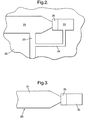
- Fig. 2 illustrates one half of an injection die in order to form a wax component pattern in accordance with the present invention. It will be appreciated that there will be at least two reciprocal injection die components which are brought into a juxtaposed position in order to create cavities for the component section and a spacer section within which the wax component pattern will be formed. These cavities will be fed through passages with wax in order to form the wax component pattern utilised in accordance with the present invention.
- a half cavity 21 with its opposed half cavity in a further injection die component (not shown) will form the component section whilst a spacer half cavity 22 again with its reciprocal half cavity in the opposed injection die component (not shown) will form the spacer section of the wax component pattern.
- the cavities 21, 22 will be fed through respective transfer passages 23, 24 with wax in order to form the wax component pattern.
- a seed crystal 25 will be located within the spacer cavity 22 such that this seed crystal 25 becomes integral with the wax either side forming the component section and the spacer section of the wax component pattern utilised in order to form a mould from which a component in accordance with the present invention will be formed.
- Fig. 3 illustrates a part of a wax component pattern subsequent to formation in an injection die 20 as depicted in Fig. 2.
- the seed crystal 25 is integrally formed in the pattern 30 between a formed wax component section 31 and a section of formed wax 32 which will constitute the spacer section 32 in the pattern 30.
- the pattern 30 will be utilised in accordance with known lost wax investment casting processes in order to form a mould in accordance with the present invention. It will be appreciated in that known lost wax technique the pattern 30 will be encased in an appropriate refractory material. The wax which forms the component section 31 and spacer section 32 will then be removed in a de-waxing stage leaving the seed crystal 35 in position.
- the mould will be formed.
- the mould will then be appropriately filled with molten castable material in order to form the component as required.
- initiation of the correct single crystal orientation is achieved through appropriate alignment of the seed crystal 35 with the directional solidification of the castable material.
- the single crystal orientation of the seed crystal 35 is extrapolated through the directional solidification process as described above. That is to say, through rendering the interface temperature of the directional solidification slightly below that of the solid with the liquid molten castable material heated to remain above that melting temperature. In such circumstances, orientation to the single grain direction is achieved.
- the present invention essentially aligns initially a wax component pattern with a single seed crystal in order to eliminate the helical constriction as described with previous methods. By such in situ alignment of the crystal seed and component sections, appropriate directional solidification propagation can be achieved.
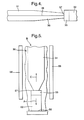
- Fig. 4 is a schematic side view of part of the pattern 30 depicted in Fig. 3, it will be seen that the seed crystal 35 progresses through a gentle blend 36 from an initial interface surface 37 through the component section 31.
- nucleation of stray grains in terms of the mechanism for such nucleation is not a thermal undercooling phenomena and is not caused by pinch-off of secondary dendritic arms which are transported by supernatant liquid flow as a result of convection in the molten castable material. Nevertheless, it can be demonstrated that nucleation of stray grains is dependent upon the choice of crystal seed alloy chemistry. Thus for example a nickel tungsten (NiW) alloy causes a localised dissolution of the nickel tungsten (NiW) surface rather than conventional melt back at that interface surface 37.
- NiW nickel tungsten
- the nickel tungsten (NiW) alloy possesses a narrow freezing (solidification) range typically less than 20° Kelvin and a cellular morphology that has no preferred crystallographic direction of growth.
- an optimum crystal seed operating temperature for transfer of crystallographic orientation can be determined in a similar fashion to conventional meltback directional solidification.
- onward directional solidification in terms of successful transfer of the initial primary orientation of the seed crystal can be achieved.
- the use of the spacer section 32 depicted in Figs. 3 and 4 is utilised in order to set that spacing for initial directional solidification and successful transfer of crystal orientation. It is crucial that the spacing between the seed crystal top surface which forms the initial interface 37 is appropriately spaced from the chiller surface which is formed by the base surface of the spacer section 32 by the initial wax pattern.
- the spacer section is filled with a suitable insulating medium such that the desired temperature control that the desired temperature control gradient is achieved for propagation and successful transfer of the primary orientation provided by the crystal 35.
- the final mould from which the investment casting of the component with the single crystal orientation will be achieved will incorporate the crystal 35 at a spaced position between sections of the mould which will form the component and a section of the mould within which insulating material will be presented.
- the present invention will utilise the lost wax process for investment moulding.
- any rough lines formed between the die components and depicted in Fig. 4 as rough edging 38 will be removed upon formation of the final refractory mould.
- the refractory mould as indicated will generally incorporate the seed crystal in accordance with the present invention at an appropriate spaced position relative to the chiller surface in order to ensure propagation of the desired orientation. Specific choice of that spacing will depend upon the castable material from which the component is to be formed as well as the seed crystal alloy chemistry as indicated above. Generally, this spacing will be in the order of 30 to 40 millimetres, but as indicated, for a nickel tungsten (NiW) seed crystal, will typically be in the range of 35 millimetres.
- NiW nickel tungsten
- Fig. 5 illustrates schematically a forming process in accordance with the present invention.
- a refractory mould 50 is formed. As indicated previously this will be achieved through a lost wax process with a component section 51 in contact with a seed crystal 55 with an interface surface 57 through which there is transfer of the crystal 55 orientation such that a cast component in the section 51 will have a single crystal grain orientation.
- a spacer section 52 is provided which is in contact through a chiller surface 56 with appropriate means for heat removal from the mould 50.
- heat transfers in the direction of arrowhead A to the chiller surface 56 and as indicated through appropriate choice of the spacing between the interface surface 57 and the chiller surface 56, successful transfer of the crystal seed 55 orientation for single grain component formation is achieved.
- molten castable material will be presented in the direction of arrowhead B and into the component section 51.
- spacer section 52 Prior to the forming process, spacer section 52 is filled with a suitable insulating medium. In such circumstances, initially the spacing between the surfaces 56, 57 is closely controlled in order to achieve the successful transfer of the seed crystal 55 primary orientation.
- a furnace 58 formed around the mould 50 is utilised in order to move the interface 57 upwards in the direction of arrowhead C, thereby forming the single crystal grain component as required.
- an integral wax component pattern is formed in which a component section consistent with the eventual desired component shape is formed on one side of the seed crystal with a spacer section formed on the other.
- a seed crystal holder may be formed integrally with these component and spacer sections such that the seed crystal is then only incorporated into the integral assembly of component section, seed crystal holder and spacer section just prior to formation of the refractory mould for forming the component.
- the seed crystal may be more conveniently removed for repeated use and potentially more accurate orientation achieved through final adjustability in the crystal holder rather than dependent upon resilient positioning of the crystal throughout the lost wax component pattern formation process as described previously.
- the spacing between the upper surface of that seed crystal with the chiller surface for successful transfer of crystal orientation which is at the core of the present invention is the spacing between the upper surface of that seed crystal with the chiller surface for successful transfer of crystal orientation which is at the core of the present invention.
- This spacing is achieved through the spacer section formed in the wax component pattern and subsequent lost wax technique for investment casting as described and known. The particular spacing as indicated will be dependent upon desired operational requirements.
Landscapes
- Engineering & Computer Science (AREA)
- Chemical & Material Sciences (AREA)
- Mechanical Engineering (AREA)
- General Engineering & Computer Science (AREA)
- Crystallography & Structural Chemistry (AREA)
- Materials Engineering (AREA)
- Metallurgy (AREA)
- Organic Chemistry (AREA)
- Crystals, And After-Treatments Of Crystals (AREA)
Abstract
Description
Claims (10)
- A casting mould (50) for casting a single crystal component comprising a seed crystal (55), a mould component section (51) and a base section for cooperation with a chiller surface (56) with a spacer section on the other side of the seed crystal, characterised in that said mould (50) defines a holder for said seed crystal (66) and said mould component section (51) is formed integrally on one side of the seed crystal (55) used to form a component presents castable material to both and a spacer section (52) is formed on the opposite side of said seed crystal (55) in order to form a component by orientation transfer from the seed crystal (55), said base surface being displaced from an interface surface (57) between the component section (51) and the seed crystal (55) to define said spacer section (52).
- A mould as claimed in claim 1 characterised in that the seed crystal is positioned by a lost wax process with lost wax presented both to the mould component section (51) and said spacer section (52) between the chiller surface (56) and the seed crystal (55).
- A mould as claimed in claim 1 or claim 2 characterised in that the displaced distance is in the order of 30 to 40 millimetres and preferably 35 millimetres between the chiller surface (56) and the interface surface (57) between the seed crystal (55) and the component section (51).
- A casting method for engine components, the method comprising forming a mould with a seed crystal (55) positioned intermediate to a mould component section (51) and a chiller surface (56), characterised in that that seed crystal (55) is spaced from the chiller surface (56) in order to facilitate through heat transfer formation of a single crystal structure by a castable material introduced into the mould component section (51).
- A method as claimed in claim 4 characterised in that the seed crystal (55) is positioned by a lost wax process with lost wax presented both to the mould component section (51) and a spacer section (52) between the chiller surface (56) and the seed crystal (55).
- A method as claimed in claim 4 or claim 5 wherein the displaced distance is in the order of 30 to 40 millimetres and preferably 35 millimetres between the chiller surface (56) and the interface surface (57) between the seed crystal (55) and the component section (52).
- A method as claimed in any of claims 4 to 5 characterised in that a mould pattern is formed comprising a mould section (51) secured to one side of the seed crystal (55) with a spacer section (52) secured to the other side of the seed crystal (55) in a forming mould.
- A method as claimed in claim 7 characterised in that wax is used to form the mould section (51) and the spacer (52) section in the blade pattern utilised to form the mould.
- A method as claimed in claim 7 or claim 8 characterised in that a pre mould comprises reciprocal half shells within which the mould pattern is formed.
- A method as claimed in claim 9 characterised in that the half shells include recesses or half cavity which constitute respective parts of the component section (52) and a spacer section (52) within which the seed crystal (55) is accommodated with respective conduit passages (23,24) formed by the juxtaposed shells through which wax for the component section (51) and the spacer section (52) is injected in order to form the blade pattern.
Applications Claiming Priority (2)
| Application Number | Priority Date | Filing Date | Title |
|---|---|---|---|
| GBGB0406102.4A GB0406102D0 (en) | 2004-03-18 | 2004-03-18 | A casting method |
| GB0406102 | 2004-03-18 |
Publications (2)
| Publication Number | Publication Date |
|---|---|
| EP1577496A2 true EP1577496A2 (en) | 2005-09-21 |
| EP1577496A3 EP1577496A3 (en) | 2007-05-23 |
Family
ID=32117947
Family Applications (1)
| Application Number | Title | Priority Date | Filing Date |
|---|---|---|---|
| EP05251042A Withdrawn EP1577496A3 (en) | 2004-03-18 | 2005-02-23 | Casting method for turbine blade |
Country Status (3)
| Country | Link |
|---|---|
| US (1) | US7204294B2 (en) |
| EP (1) | EP1577496A3 (en) |
| GB (1) | GB0406102D0 (en) |
Cited By (3)
| Publication number | Priority date | Publication date | Assignee | Title |
|---|---|---|---|---|
| EP1793020A1 (en) * | 2005-12-01 | 2007-06-06 | Rolls-Royce plc | A method and mould for casting articles with a pre-determined crystalline orientation |
| CN109338455A (en) * | 2018-10-10 | 2019-02-15 | 深圳市万泽中南研究院有限公司 | Manufacturing method, system and the equipment of single crystal casting |
| CN117444140A (en) * | 2023-12-22 | 2024-01-26 | 中国航发北京航空材料研究院 | Secondary orientation controllable polycrystalline test plate wax mould and preparation method of wax mould |
Families Citing this family (13)
| Publication number | Priority date | Publication date | Assignee | Title |
|---|---|---|---|---|
| US7762309B2 (en) | 2007-09-24 | 2010-07-27 | Siemens Energy, Inc. | Integral single crystal/columnar grained component and method of casting the same |
| RU2402111C2 (en) * | 2008-07-18 | 2010-10-20 | Общество С Ограниченной Ответственностью Научно-Производственное Объединение "Кристалл" | Crystal plate, rectangular bar, component for making thermoelectric modules and method of making crystal plate |
| CN102101265B (en) * | 2010-12-16 | 2012-05-16 | 浙江工业大学 | Clamp for detecting stress of polished workpiece and positioning working original point of polishing tool |
| US8770944B2 (en) | 2011-03-31 | 2014-07-08 | General Electric Company | Turbine airfoil component and method for making |
| US8714235B2 (en) | 2011-12-30 | 2014-05-06 | United Technologies Corporation | High temperature directionally solidified and single crystal die casting |
| CN107745093B (en) * | 2017-12-06 | 2023-06-06 | 安徽应流航源动力科技有限公司 | Fine casting module and casting method for preparing nickel-based single crystal guide vane with precisely controllable crystal orientation by utilizing fine casting module |
| US10633760B2 (en) | 2018-04-05 | 2020-04-28 | United Technologies Corporation | Method to prevent gap in cylindral seeds around an internal ceramic core |
| US11377753B2 (en) | 2019-10-04 | 2022-07-05 | Raytheon Technologies Corporation | Arcuate seed casting method |
| US11198175B2 (en) | 2019-10-04 | 2021-12-14 | Raytheon Technologies Corporation | Arcuate seed casting method |
| US11383295B2 (en) | 2019-10-04 | 2022-07-12 | Raytheon Technologies Corporation | Arcuate seed casting method |
| CN114273610B (en) * | 2021-12-01 | 2024-06-25 | 东方电气集团东方汽轮机有限公司 | A mold shell for directional crystallization blade investment casting and preparation method thereof |
| CN114618993B (en) * | 2022-03-05 | 2023-05-12 | 湘潭大学 | Method for preparing single crystal superalloy by using cooling plate with holes to assist <001> oriented seed crystal |
| GB202308344D0 (en) | 2023-06-05 | 2023-07-19 | Rolls Royce Plc | Method of manufacturing component |
Family Cites Families (17)
| Publication number | Priority date | Publication date | Assignee | Title |
|---|---|---|---|---|
| GB822533A (en) | 1956-09-20 | 1959-10-28 | Gen Electric | Improvements in grain oriented ingots |
| US3787190A (en) * | 1970-06-01 | 1974-01-22 | United Aircraft Corp | Directionally solidified article |
| US4015657A (en) | 1975-09-03 | 1977-04-05 | Dmitry Andreevich Petrov | Device for making single-crystal products |
| US4714101A (en) * | 1981-04-02 | 1987-12-22 | United Technologies Corporation | Method and apparatus for epitaxial solidification |
| GB2112309B (en) * | 1981-12-23 | 1986-01-02 | Rolls Royce | Making a cast single crystal article |
| US4475582A (en) | 1982-01-27 | 1984-10-09 | United Technologies Corporation | Casting a metal single crystal article using a seed crystal and a helix |
| US4412577A (en) * | 1982-01-27 | 1983-11-01 | United Technologies Corporation | Control of seed melt-back during directional solidification of metals |
| US4580613A (en) * | 1982-08-05 | 1986-04-08 | Howmet Turbine Components Corporation | Method and mold for casting articles having a predetermined crystalline orientation |
| JPH0292888A (en) * | 1988-09-30 | 1990-04-03 | Agency Of Ind Science & Technol | Production of single crystal of nickel-based superalloy |
| DE4039808C1 (en) * | 1990-12-13 | 1992-01-02 | Mtu Muenchen Gmbh | |
| RU2080209C1 (en) | 1993-12-29 | 1997-05-27 | Всероссийский научно-исследовательский институт авиационных материалов | Device for production of single-crystal ingots |
| DE19611866A1 (en) | 1996-03-26 | 1997-10-02 | Lyulka Saturn Inc | Casting mould for production of single crystal casting having growth cavity and nucleation cavity |
| US6446701B1 (en) | 1997-04-11 | 2002-09-10 | Niranjan Das | Apparatus for unidirectional solidification of compounds |
| JPH11322499A (en) | 1998-05-18 | 1999-11-24 | Mitsubishi Heavy Ind Ltd | Production of single crystal material |
| RU2184010C1 (en) | 2000-12-07 | 2002-06-27 | Государственное предприятие "Всероссийский научно-исследовательский институт авиационных материалов" | Apparatus for making castings with monocrystalline structure |
| US7575038B2 (en) * | 2001-06-11 | 2009-08-18 | Howmet Research Corporation | Single crystal seed |
| US20040167270A1 (en) * | 2003-02-25 | 2004-08-26 | Dane Chang | Fugitive pattern for casting |
-
2004
- 2004-03-18 GB GBGB0406102.4A patent/GB0406102D0/en not_active Ceased
-
2005
- 2005-02-23 EP EP05251042A patent/EP1577496A3/en not_active Withdrawn
- 2005-02-25 US US11/065,442 patent/US7204294B2/en not_active Expired - Lifetime
Cited By (6)
| Publication number | Priority date | Publication date | Assignee | Title |
|---|---|---|---|---|
| EP1793020A1 (en) * | 2005-12-01 | 2007-06-06 | Rolls-Royce plc | A method and mould for casting articles with a pre-determined crystalline orientation |
| US7449063B2 (en) | 2005-12-01 | 2008-11-11 | Rolls-Royce Plc | Method and mould for casting articles with a pre-determined crystalline orientation |
| US8382899B2 (en) | 2005-12-01 | 2013-02-26 | Rolls-Royce Plc | Method and mould for casting articles with a pre-determined crystalline orientation |
| CN109338455A (en) * | 2018-10-10 | 2019-02-15 | 深圳市万泽中南研究院有限公司 | Manufacturing method, system and the equipment of single crystal casting |
| CN117444140A (en) * | 2023-12-22 | 2024-01-26 | 中国航发北京航空材料研究院 | Secondary orientation controllable polycrystalline test plate wax mould and preparation method of wax mould |
| CN117444140B (en) * | 2023-12-22 | 2024-03-26 | 中国航发北京航空材料研究院 | Polycrystalline test plate wax pattern mold with controllable secondary orientation and preparation method of wax pattern |
Also Published As
| Publication number | Publication date |
|---|---|
| US20050205002A1 (en) | 2005-09-22 |
| US7204294B2 (en) | 2007-04-17 |
| GB0406102D0 (en) | 2004-04-21 |
| EP1577496A3 (en) | 2007-05-23 |
Similar Documents
| Publication | Publication Date | Title |
|---|---|---|
| US7204294B2 (en) | Casting method | |
| RU2647422C2 (en) | Shell-shaped form having a thermal protection screen | |
| US4580613A (en) | Method and mold for casting articles having a predetermined crystalline orientation | |
| JPH0126796B2 (en) | ||
| CN103143678B (en) | Formwork for optimizing directional columnar crystal structure of high-temperature alloy blade | |
| EP0087379B1 (en) | Casting a metal single crystal article using a seed crystal and a helix | |
| EP0127552B1 (en) | Casting of articles with predetermined crystalline orientation | |
| GB2037200A (en) | Epitaxial solidification | |
| US9144842B2 (en) | Unidirectional solidification process and apparatus and single-crystal seed therefor | |
| CN105121064B (en) | Monocrystalline melting mould | |
| EP1093872B1 (en) | Controlling grain spacing in directional solidified castings | |
| EP2165787A1 (en) | Directional solidification mould | |
| EP2182098A2 (en) | Process for casting columnar grain airfoil with preferential primary orientation | |
| EP2902135B1 (en) | Casting method and cast article | |
| CN119407107A (en) | A single crystal high temperature alloy turbine blade shell and preparation method thereof | |
| US10507521B2 (en) | Mould for casting a monocrystalline component | |
| Toloraiya et al. | Advanced method for single crystal casting of turbine blades for gas turbine engines and plants | |
| JP7590990B2 (en) | Mold for manufacturing components by metal injection and epitaxial growth and associated manufacturing method - Patents.com | |
| EP2166133B1 (en) | Metal casting | |
| US10265764B2 (en) | Casting method and cast article | |
| EP3335817A1 (en) | Casting method and cast article |
Legal Events
| Date | Code | Title | Description |
|---|---|---|---|
| PUAI | Public reference made under article 153(3) epc to a published international application that has entered the european phase |
Free format text: ORIGINAL CODE: 0009012 |
|
| AK | Designated contracting states |
Kind code of ref document: A2 Designated state(s): AT BE BG CH CY CZ DE DK EE ES FI FR GB GR HU IE IS IT LI LT LU MC NL PL PT RO SE SI SK TR |
|
| AX | Request for extension of the european patent |
Extension state: AL BA HR LV MK YU |
|
| PUAL | Search report despatched |
Free format text: ORIGINAL CODE: 0009013 |
|
| AK | Designated contracting states |
Kind code of ref document: A3 Designated state(s): AT BE BG CH CY CZ DE DK EE ES FI FR GB GR HU IE IS IT LI LT LU MC NL PL PT RO SE SI SK TR |
|
| AX | Request for extension of the european patent |
Extension state: AL BA HR LV MK YU |
|
| RIC1 | Information provided on ipc code assigned before grant |
Ipc: C30B 11/00 20060101ALI20070413BHEP Ipc: F01D 5/14 20060101AFI20050413BHEP |
|
| 17P | Request for examination filed |
Effective date: 20070502 |
|
| AKX | Designation fees paid |
Designated state(s): DE FR GB |
|
| 17Q | First examination report despatched |
Effective date: 20080425 |
|
| STAA | Information on the status of an ep patent application or granted ep patent |
Free format text: STATUS: THE APPLICATION IS DEEMED TO BE WITHDRAWN |
|
| 18D | Application deemed to be withdrawn |
Effective date: 20080906 |