EP1577487B1 - Power slip for drill pipe - Google Patents
Power slip for drill pipe Download PDFInfo
- Publication number
- EP1577487B1 EP1577487B1 EP05251488A EP05251488A EP1577487B1 EP 1577487 B1 EP1577487 B1 EP 1577487B1 EP 05251488 A EP05251488 A EP 05251488A EP 05251488 A EP05251488 A EP 05251488A EP 1577487 B1 EP1577487 B1 EP 1577487B1
- Authority
- EP
- European Patent Office
- Prior art keywords
- slip
- pulling mechanism
- rotary table
- automated
- arm
- Prior art date
- Legal status (The legal status is an assumption and is not a legal conclusion. Google has not performed a legal analysis and makes no representation as to the accuracy of the status listed.)
- Expired - Lifetime
Links
- 238000005553 drilling Methods 0.000 claims abstract description 14
- 238000000034 method Methods 0.000 claims description 9
- 230000001681 protective effect Effects 0.000 claims description 7
- 230000000712 assembly Effects 0.000 description 2
- 238000000429 assembly Methods 0.000 description 2
- 230000006378 damage Effects 0.000 description 2
- 239000012530 fluid Substances 0.000 description 2
- 239000000463 material Substances 0.000 description 2
- 208000027418 Wounds and injury Diseases 0.000 description 1
- 238000010276 construction Methods 0.000 description 1
- 230000001747 exhibiting effect Effects 0.000 description 1
- 231100001261 hazardous Toxicity 0.000 description 1
- 208000014674 injury Diseases 0.000 description 1
- 238000000465 moulding Methods 0.000 description 1
- 239000003208 petroleum Substances 0.000 description 1
- 229910001220 stainless steel Inorganic materials 0.000 description 1
- 239000010935 stainless steel Substances 0.000 description 1
- XLYOFNOQVPJJNP-UHFFFAOYSA-N water Substances O XLYOFNOQVPJJNP-UHFFFAOYSA-N 0.000 description 1
- 238000003466 welding Methods 0.000 description 1
Images




Classifications
-
- E—FIXED CONSTRUCTIONS
- E21—EARTH OR ROCK DRILLING; MINING
- E21B—EARTH OR ROCK DRILLING; OBTAINING OIL, GAS, WATER, SOLUBLE OR MELTABLE MATERIALS OR A SLURRY OF MINERALS FROM WELLS
- E21B19/00—Handling rods, casings, tubes or the like outside the borehole, e.g. in the derrick; Apparatus for feeding the rods or cables
- E21B19/10—Slips; Spiders ; Catching devices
Definitions
- the present invention relates generally to a slip-type apparatus for gripping and manipulating tubular members, such as drill pipe and bottom-hole assembly components. More specifically, the present invention relates to an automated apparatus for manipulating pipe members into and out of petroleum wells.
- a typical slip-type apparatus generally comprises a plurality of circumferentially spaced slip bodies that can be placed around the locus of a drill pipe or other tubular member.
- the inner sides of the slip bodies carry gripping members, usually in the form of teeth, for frictionally engaging the drill pipe or tubular member.
- the outer sides of the slip bodies generally have tapered surfaces that are inclined inwardly from top to bottom.
- the slip-type apparatus In a typical well drilling operation, the slip-type apparatus is secured around the pipe member and placed in the portion of the rotary table referred to as the rotary table bushing or "bowl." Because the slip bodies can move both longitudinally and radially with respect to the bowl, these inclined surfaces serve as camming surfaces. Thus, when the weight of the pipe member is set down on the slip-type apparatus, so that it tends to move the slip bodies downwardly with respect to the bowl, the camming surfaces urge the slip bodies radially inwardly and into tighter engagement with the pipe member. Once set, the slips will support the weight of the drill pipe and/or other tubular members suspended therefrom.
- slip-type devices were manipulated manually by individuals working on the rig floor referred to as "roughnecks.”
- automated "slip pullers” were developed. These devices essentially secured the slip-type device around the pipe member and in and out of the bowl without direct human intervention. While an improvement over the manual process, the automated slip puller did not eliminate risk entirely.
- US-2003/0227187 disclose a casing slip liner which includes a frame, upper and lower lift arm assemblies and a wrap arm to which the slips are attached and which is coupled to the arm assemblies by a hinge.
- the present invention provides an automated slip pulling apparatus for manipulating tubular members, including drill pipe and drill collars.
- the apparatus comprises a slip base, a pulling mechanism pivotally attached to the slip base, and at least one cylinder or spring attached to the pulling mechanism.
- the pulling mechanism comprises a top arm, at least one bottom arm, and a pull arm, all interconnected to the other components and the slip base.
- Alternative embodiments may comprise additional components and/or multiple segments.
- the entire apparatus is releasably attached to a rotary table located over a borehole.
- the automated slip puller apparatus is attached to a slip assembly that is well known in the prior art.
- the slips are placed around a drill pipe and secured in the rotary table bushing.
- the pulling mechanism removes the slips from the rotary table bushing and from around the drill pipe, thereby allowing the drill pipe to be run into or out of the well bore.
- no portion of the automated slip puller is located outside the boundary of the rotary table. Because the entirety of the automated slip puller is located substantially within the boundaries of the rotary table, the present invention provides a safer working environment than did previous mechanical slip pullers.
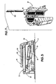
- FIGS. 2 (a-b) and 3 An automated slip puller assembly according to the present invention is shown generally at FIGS. 2 (a-b) and 3.
- a slip base 1 is mounted on top of the rotary table 21 and may be secured thereto via pins (not shown) on the bottom of the slip base 1 that mate with the receptacles 19 in the rotary table 21 for the kelly bushing, or any other suitable means.
- the slip base 1 may contain magnets 12 that secure the slip puller to the rotary table 21 and eliminate any excessive vibration during operation. The magnets 12 may be utilized solely, or in conjunction with the pins previously described.
- the slip base 1 is generally circular and contains a U-shaped cutout that allows for the rotary table bushing or bowl 18 to be exposed.
- the slip base 1 is otherwise substantially the same diameter as the rotary table 21.
- the slip base 1 also comprises a vertical extension 17 for connecting additional slip puller components.
- the slip base 1 effectively supports a top arm 2, two bottom arms 3 (only one is shown), a pull arm 5, and a pull arm extension 8. This combination of components is referred to generally as the pulling mechanism.
- the pulling mechanism is attached to the vertical extension 17 portion of the slip base 1.
- the top arm 2 of the automated slip puller is generally U-shaped and effectively mirrors the U-shaped cutout of the slip base 1.
- the top arm is located above the bottom arms 3, below the pull arm 5, and is secured to the other components via pins or an effective equivalent.
- the top arm 2 may be formed by welding, molding, or any other suitable means.
- the bottom arms 3 are located directly under the top arm and run longitudinally and radially parallel to the limb portions 13 of the top arm 2. The bottom arms 3 are secured to the slip base 1 and other components via pins or an effective equivalent.
- Two slip cylinders 6 and 7 are located between the limb portions 13 of the top arm 2 and the bottom arms 3, and connect the top arm 2 and bottom arms 3 via pins or an effective equivalent.
- the slip cylinders 6 and 7 run longitudinally and radially parallel to the limb portions 13 of the top arm 2 and the bottom arms 3.
- the slip cylinders can be hydraulic, pneumatic, or similar-type cylinders.
- the slip cylinders are preferably hydraulic cylinders due to the compact design of most commercially available hydraulic cylinders.
- the hydraulic cylinders are activated by water.
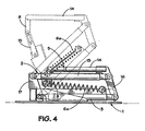
- the slip cylinders 6 and 7 are replaced by two springs 6a (only one is shown in the view of FIG. 4).
- the springs 6a connect the top arm 2 and bottom arms 3 via pins or an effective equivalent and run longitudinally and radially parallel to the limb portions 13 of the top 2 and the bottom arms 3.
- the pull arm 5 is located at the top of the automated slip puller, above the top arm 2. Similar to the top arm 2, the pull arm 5 is effectively U-shaped. However, in the preferred embodiment, the base of the "U” is located closer to the cutout portion of the slip base 1 when viewing the automated slip puller from above.
- the limbs 14 of the pull arm 5 run longitudinally and radially parallel to the limbs 13 of the top arm 2 and bottom arms 3, except for the connective portion 16 located at the end of the limbs 14. This portion of the pull arm 5 is directed downward towards the slip base 1 and connects the bottoms arms 3 and top arm 2 to the pull arm 5.
- the pull arm extension 8 extends downward from the pull arm 5 and connects the pull arm 5 to an accommodating link 15 (shown in FIG. 4).
- the accommodating link 15, in turn, connects the pull arm extension 8 to the slips 9.
- the accommodating link 15 is preferably arranged in a configuration that allows for a certain freedom of movement - such as a chain link or slotted link configuration. This type of configuration allows for varying sizes of slips 9 to rest within the rotary table bushing when placed around a drill pipe or other tubular member. This, in turn, avoids placing any strain on the automated slip puller from the weight of the tubular member.
- FIGS. 5a through 5d a preferred embodiment of the present invention is shown in operation.
- a slip cylinder 6 is shown in an extended position. This position of the slip cylinder 6 places the slips 9 within the rotary table bushing or bowl. This position is referred to as the "deactivated" position.
- FIGS. 5b and 5c demonstrate the movement of the slip puller as the slip cylinder 6 is being manipulated into a retracted position and the slips 9 are removed from the bowl and from around a tubular member such as drill pipe (not shown).
- the bottoms arms 3 and top arm 2 are manipulated effectively upward by the slip cylinder 6. As these members are manipulated, the bottom arms 3 and the limbs of the top arm 2 remain substantially parallel to each other and effectively form a parallelogram.
- the pull arm 5 remains substantially parallel to the slip base 1.
- Fig 5d shows the slip cylinder 6 in the fully retracted position and the slips 9 completely removed from the bowl and drill pipe.
- This position is referred to as the "activated" position.
- the bottom arm 3 and the limbs of the top arm 2 are still substantially parallel to each other (again effectively exhibiting a parallelogram geometry), while the pull arm 5 is substantially parallel to the slip base 1.
- the pulling radius R of the pull arm 5 is shown in FIG. 5a.
- the slip cylinders 6 and 7 of the automated slip puller are operated remotely from the drill floor via a pedal.
- the slip cylinders 6 and 7 of the automated slip puller may be operated from the driller's control panel or another suitable location.
- the automated slip puller is substantially the same as described above, but is manipulated between the activated and deactivated position by one or more springs 6a (only one is shown in FIG. 4).
- the spring is biased in an extended position, which results in the automated slip puller being biased in the activated position as shown in FIG. 4.
- the weight of the tubular member overcomes the natural bias of the springs 6a and places the slips 9 within the rotary table bushing or bowl.
- the bias of the springs 6a manipulates the automated slip puller back to the activated position and removes the slips 9 from within the bowl.
- FIGs. 6a and 6c show the automated slip puller of the present invention covered by a protective sheath 10 formed of stainless steel, plastic, rubber, or other suitable material.
- the protective sheath 10 protects the components of the slip puller from exposure to drilling fluids or other hazardous and/or corrosive materials that accompany typical well drilling operations.
- FIG. 6b shows the automated slip puller in the activated position.
- a protective cover 11 shields the bottom arms, the top arm, and the slip cylinders from drilling fluids and the like.
- the protective cover 11 may be separate from the protective sheath 10 or an integral part thereof.
- slips 9 comprise three separate slip segments with hinges connecting the three components together.
- teeth 20 On the interior portion of the slip components are located teeth 20 for frictionally engaging drill pipe or other tubular members. This configuration has been in use for several years and is well known in the prior art.
- the slip configuration shown in FIG. 7 is readily transformable from a manual slip type to one compatible with the automated slip puller of the present invention.
- the handles (not shown) for the slips 9 are removed and the slips 9 are suspended from the pull arm extension 8 by connecting the accommodating link 15 to a suitable attachment point on the central slip segment of the slips 9 (as shown in FIGS 5(a-d)).
Landscapes
- Engineering & Computer Science (AREA)
- Geology (AREA)
- Mining & Mineral Resources (AREA)
- Life Sciences & Earth Sciences (AREA)
- General Life Sciences & Earth Sciences (AREA)
- Fluid Mechanics (AREA)
- Environmental & Geological Engineering (AREA)
- Physics & Mathematics (AREA)
- Mechanical Engineering (AREA)
- Geochemistry & Mineralogy (AREA)
- Earth Drilling (AREA)
- Drilling And Boring (AREA)
- Footwear And Its Accessory, Manufacturing Method And Apparatuses (AREA)
- Drilling Tools (AREA)
- Electrical Discharge Machining, Electrochemical Machining, And Combined Machining (AREA)
- Branch Pipes, Bends, And The Like (AREA)
Abstract
Description
- The present invention relates generally to a slip-type apparatus for gripping and manipulating tubular members, such as drill pipe and bottom-hole assembly components. More specifically, the present invention relates to an automated apparatus for manipulating pipe members into and out of petroleum wells.
- A typical slip-type apparatus generally comprises a plurality of circumferentially spaced slip bodies that can be placed around the locus of a drill pipe or other tubular member. The inner sides of the slip bodies carry gripping members, usually in the form of teeth, for frictionally engaging the drill pipe or tubular member. The outer sides of the slip bodies generally have tapered surfaces that are inclined inwardly from top to bottom.
- In a typical well drilling operation, the slip-type apparatus is secured around the pipe member and placed in the portion of the rotary table referred to as the rotary table bushing or "bowl." Because the slip bodies can move both longitudinally and radially with respect to the bowl, these inclined surfaces serve as camming surfaces. Thus, when the weight of the pipe member is set down on the slip-type apparatus, so that it tends to move the slip bodies downwardly with respect to the bowl, the camming surfaces urge the slip bodies radially inwardly and into tighter engagement with the pipe member. Once set, the slips will support the weight of the drill pipe and/or other tubular members suspended therefrom.
- In the past, such slip-type devices were manipulated manually by individuals working on the rig floor referred to as "roughnecks." The operation of securing the slip-type apparatus around the pipe member and in and out of the bowl presented a certain degree of danger to the roughnecks - accidents were commonplace. To alleviate this dangerous situation, automated "slip pullers" were developed. These devices essentially secured the slip-type device around the pipe member and in and out of the bowl without direct human intervention. While an improvement over the manual process, the automated slip puller did not eliminate risk entirely.
- The automated slip pullers of the prior art were designed such that the devices were secured over the rotary table - usually via the drive or "kelly" bushings. Due to the unique operation of the prior art devices, the body of the slip pullers extended beyond the boundaries of the rotary table below. Such a prior art device is demonstrated in FIGS. 1 (a-c).
- This design presented a potentially dangerous situation. If the rotary table began to spin with the automated slip puller attached, that portion of the device that extended beyond the boundary of the rotary table would spin as well, causing damage to any equipment, or injury to any individual, near the area. The present invention eliminates this potentially dangerous situation.
-
US-2003/0227187 disclose a casing slip liner which includes a frame, upper and lower lift arm assemblies and a wrap arm to which the slips are attached and which is coupled to the arm assemblies by a hinge. - The invention is set out in
claims 1 and 12. - The present invention provides an automated slip pulling apparatus for manipulating tubular members, including drill pipe and drill collars. The apparatus comprises a slip base, a pulling mechanism pivotally attached to the slip base, and at least one cylinder or spring attached to the pulling mechanism. The pulling mechanism comprises a top arm, at least one bottom arm, and a pull arm, all interconnected to the other components and the slip base. Alternative embodiments may comprise additional components and/or multiple segments. The entire apparatus is releasably attached to a rotary table located over a borehole.
- In a typical well drilling operation, the automated slip puller apparatus is attached to a slip assembly that is well known in the prior art. The slips are placed around a drill pipe and secured in the rotary table bushing. When the automated slip puller is activated, the pulling mechanism removes the slips from the rotary table bushing and from around the drill pipe, thereby allowing the drill pipe to be run into or out of the well bore. During operation, no portion of the automated slip puller is located outside the boundary of the rotary table. Because the entirety of the automated slip puller is located substantially within the boundaries of the rotary table, the present invention provides a safer working environment than did previous mechanical slip pullers.
- Additional objects and advantages of the invention will become apparent as the following detailed description of the preferred embodiment is read in conjunction with the drawings which illustrate the preferred embodiment.
-
- FIGS. 1 (a-c) do not represent the present invention but are presented to illustrate the prior art.
- FIGS. 2 (a-b) show top views of the automated slip puller assembly of the present invention.
- FIG. 3 shows a side view of the automated slip puller assembly of the present invention.
- FIG. 4 shows a side view of an alternative embodiment of the automated slip puller assembly of the present invention.
- FIGS. 5 (a-d) show the operation of the automated slip puller assembly of the present invention from the side view.
- FIGS. 6 (a-c) show the automated slip puller assembly of the present invention encased in a protective sheath.
- FIG. 7 shows an exploded view of a slip assembly used in conjunction with the present invention.
- An automated slip puller assembly according to the present invention is shown generally at FIGS. 2 (a-b) and 3. In a first embodiment, a slip base 1 is mounted on top of the rotary table 21 and may be secured thereto via pins (not shown) on the bottom of the slip base 1 that mate with the
receptacles 19 in the rotary table 21 for the kelly bushing, or any other suitable means. In an alternative embodiment, the slip base 1 may containmagnets 12 that secure the slip puller to the rotary table 21 and eliminate any excessive vibration during operation. Themagnets 12 may be utilized solely, or in conjunction with the pins previously described. - The slip base 1 is generally circular and contains a U-shaped cutout that allows for the rotary table bushing or
bowl 18 to be exposed. The slip base 1 is otherwise substantially the same diameter as the rotary table 21. The slip base 1 also comprises avertical extension 17 for connecting additional slip puller components. In the first embodiment, the slip base 1 effectively supports atop arm 2, two bottom arms 3 (only one is shown), apull arm 5, and apull arm extension 8. This combination of components is referred to generally as the pulling mechanism. The pulling mechanism is attached to thevertical extension 17 portion of the slip base 1. - The
top arm 2 of the automated slip puller is generally U-shaped and effectively mirrors the U-shaped cutout of the slip base 1. The top arm is located above thebottom arms 3, below thepull arm 5, and is secured to the other components via pins or an effective equivalent. Thetop arm 2 may be formed by welding, molding, or any other suitable means. Thebottom arms 3 are located directly under the top arm and run longitudinally and radially parallel to thelimb portions 13 of thetop arm 2. Thebottom arms 3 are secured to the slip base 1 and other components via pins or an effective equivalent. - Two
slip cylinders limb portions 13 of thetop arm 2 and thebottom arms 3, and connect thetop arm 2 andbottom arms 3 via pins or an effective equivalent. Theslip cylinders limb portions 13 of thetop arm 2 and thebottom arms 3. The slip cylinders can be hydraulic, pneumatic, or similar-type cylinders. The slip cylinders are preferably hydraulic cylinders due to the compact design of most commercially available hydraulic cylinders. Preferably, the hydraulic cylinders are activated by water. - In an alternative embodiment represented in FIG. 4, the
slip cylinders springs 6a (only one is shown in the view of FIG. 4). As with theslips cylinders springs 6a connect thetop arm 2 andbottom arms 3 via pins or an effective equivalent and run longitudinally and radially parallel to thelimb portions 13 of thetop 2 and thebottom arms 3. - Returning to FIGS. 2 and 3, the
pull arm 5 is located at the top of the automated slip puller, above thetop arm 2. Similar to thetop arm 2, thepull arm 5 is effectively U-shaped. However, in the preferred embodiment, the base of the "U" is located closer to the cutout portion of the slip base 1 when viewing the automated slip puller from above. Thelimbs 14 of thepull arm 5 run longitudinally and radially parallel to thelimbs 13 of thetop arm 2 andbottom arms 3, except for theconnective portion 16 located at the end of thelimbs 14. This portion of thepull arm 5 is directed downward towards the slip base 1 and connects thebottoms arms 3 andtop arm 2 to thepull arm 5. - At the base of the "U" portion of the
pull arm 5, is thepull arm extension 8. Thepull arm extension 8 extends downward from thepull arm 5 and connects thepull arm 5 to an accommodating link 15 (shown in FIG. 4). Theaccommodating link 15, in turn, connects thepull arm extension 8 to theslips 9. Theaccommodating link 15 is preferably arranged in a configuration that allows for a certain freedom of movement - such as a chain link or slotted link configuration. This type of configuration allows for varying sizes ofslips 9 to rest within the rotary table bushing when placed around a drill pipe or other tubular member. This, in turn, avoids placing any strain on the automated slip puller from the weight of the tubular member. - Referring now to FIGS. 5a through 5d, a preferred embodiment of the present invention is shown in operation. Referring specifically to FIG. 5a, a
slip cylinder 6 is shown in an extended position. This position of theslip cylinder 6 places theslips 9 within the rotary table bushing or bowl. This position is referred to as the "deactivated" position. FIGS. 5b and 5c demonstrate the movement of the slip puller as theslip cylinder 6 is being manipulated into a retracted position and theslips 9 are removed from the bowl and from around a tubular member such as drill pipe (not shown). As the figures demonstrate, thebottoms arms 3 andtop arm 2 are manipulated effectively upward by theslip cylinder 6. As these members are manipulated, thebottom arms 3 and the limbs of thetop arm 2 remain substantially parallel to each other and effectively form a parallelogram. In contrast, thepull arm 5 remains substantially parallel to the slip base 1. - Fig 5d shows the
slip cylinder 6 in the fully retracted position and theslips 9 completely removed from the bowl and drill pipe. This position is referred to as the "activated" position. In this position, thebottom arm 3 and the limbs of thetop arm 2 are still substantially parallel to each other (again effectively exhibiting a parallelogram geometry), while thepull arm 5 is substantially parallel to the slip base 1. The pulling radius R of thepull arm 5 is shown in FIG. 5a. As the automated slip puller is manipulated from the deactivated to the activated position, it is apparent from FIGS. 5 (a-d) that substantially no portion of the apparatus extends beyond the boundaries of the rotary table. - In one embodiment of the invention described above, the
slip cylinders slip cylinders - In an alternative embodiment of the invention as shown in FIG. 4, the automated slip puller is substantially the same as described above, but is manipulated between the activated and deactivated position by one or
more springs 6a (only one is shown in FIG. 4). The spring is biased in an extended position, which results in the automated slip puller being biased in the activated position as shown in FIG. 4. When theslips 9 are thereafter placed around a tubular member, the weight of the tubular member overcomes the natural bias of thesprings 6a and places theslips 9 within the rotary table bushing or bowl. Once the tubular member is lifted from the bowl, the bias of thesprings 6a manipulates the automated slip puller back to the activated position and removes theslips 9 from within the bowl. - FIGs. 6a and 6c show the automated slip puller of the present invention covered by a
protective sheath 10 formed of stainless steel, plastic, rubber, or other suitable material. When in the deactivated position, theprotective sheath 10 protects the components of the slip puller from exposure to drilling fluids or other hazardous and/or corrosive materials that accompany typical well drilling operations. FIG. 6b shows the automated slip puller in the activated position. Aprotective cover 11 shields the bottom arms, the top arm, and the slip cylinders from drilling fluids and the like. Theprotective cover 11 may be separate from theprotective sheath 10 or an integral part thereof. - Referring now to FIG. 7, a standard set of
slips 9 is shown in exploded detail. Theslips 9 comprise three separate slip segments with hinges connecting the three components together. On the interior portion of the slip components are locatedteeth 20 for frictionally engaging drill pipe or other tubular members. This configuration has been in use for several years and is well known in the prior art. - The slip configuration shown in FIG. 7 is readily transformable from a manual slip type to one compatible with the automated slip puller of the present invention. The handles (not shown) for the
slips 9 are removed and theslips 9 are suspended from thepull arm extension 8 by connecting theaccommodating link 15 to a suitable attachment point on the central slip segment of the slips 9 (as shown in FIGS 5(a-d)). - While preferred embodiments of the apparatus have been discussed for the purposes of this disclosure, numerous changes in the arrangement and construction of the automated slip puller may be made by those skilled in the art. All such changes are encompassed within the scope and spirit of the following claims.
Claims (19)
- An automated slip puller apparatus comprising:(a) a slip base (1) located on a rotary table (21);(b) a pulling mechanism comprising a bottom arm (3) and a top arm (2), each pivotally attached to the slip base at respective first ends, and a pull arm (5) pivotably attached to the bottom and top arm at respective second ends,(c) slips (9) connected to the pull arm; and(d) at least one cylinder (6,7) connected to the pulling mechanism and operable to move the pulling mechanism between an activated and a deactivated position,characterised in that the pull arm (5) extends in a direction from the second ends towards the first ends, whereby no portion of the pulling mechanism is outside of the boundary of the rotary table (21).
- The automated slip puller apparatus of claim 1, wherein the slip base (1) is connected to the rotary table via the kelly bushing receptacles.
- The automated slip puller apparatus of claim 1, wherein the slip base is connected to the rotary table via magnets (12).
- The automated slip puller apparatus of claim 1, wherein the cylinder (6,7) comprises a hydraulic cylinder.
- The automated slip puller apparatus of claim 1, wherein the cylinder (6,7) comprises a pneumatic cylinder.
- The automated slip puller apparatus of claim 1, wherein the slips are suspended from an accommodating link connected to a pull arm extension.
- The automated slip puller apparatus of claim 1, wherein the bottom arm (3) and the top arm (2) exhibit a parallelogram geometry, both in the activated and deactivated position.
- The automated slip puller apparatus of claim 1, wherein the pulling mechanism is encased in a protective sheath (10,11).
- The automated slip puller apparatus of claim 1, wherein the apparatus is manipulated via remote control.
- The automated slip puller apparatus of claim 1, wherein no portion of the pulling mechanism is outside the boundary of the rotary table when in the activated position.
- The automated slip puller apparatus of claim 1, wherein no portion of the automated slip puller is outside the boundary of the rotary table.
- A well drilling process comprising the steps of:constructing a power slip apparatus comprising at least:(a) a slip base (1) located on a rotary table (21);(b) a pulling mechanism comprising a bottom arm (3) and a top arm (2), each pivotally attached to the slip base at respective first ends, and a pull arm (5) pivotably attached to the bottom and top arm at respective second ends;(c) slips (9) connected to the pulling mechanism;characterized in that the pull arm (5) extends in a direction from the second ends towards the first ends, andmanipulating the pulling mechanism between an activated and a deactivated wherein no portion of the pulling mechanism is outside of the boundary of the rotary table.
- The well drilling process of claim 12, wherein the pulling mechanism is manipulated by means of a cylinder (6,7).
- The well drilling process of claim 12, wherein the pulling mechanism is manipulated by means of a spring.
- The well drilling process of claim 13, wherein the cylinder (6,7) comprises a hydraulic cylinder.
- The well drilling process of claim 13, wherein the cylinder (6,7) comprises a pneumatic cylinder.
- The well drilling process of claim 12, wherein the pulling mechanism is manipulated via remote control.
- The well drilling process of claim 12, wherein the pulling mechanism exhibits a parallelogram geometry both in the activated and deactivated position.
- The well drilling process of claim 12, wherein no portion of the pulling mechanism is outside the boundary of the rotary table when in an activated position.
Applications Claiming Priority (2)
| Application Number | Priority Date | Filing Date | Title |
|---|---|---|---|
| US799511 | 1985-11-19 | ||
| US10/799,511 US7293618B2 (en) | 2004-03-12 | 2004-03-12 | Power slip for drillpipe |
Publications (2)
| Publication Number | Publication Date |
|---|---|
| EP1577487A1 EP1577487A1 (en) | 2005-09-21 |
| EP1577487B1 true EP1577487B1 (en) | 2007-10-31 |
Family
ID=34838868
Family Applications (1)
| Application Number | Title | Priority Date | Filing Date |
|---|---|---|---|
| EP05251488A Expired - Lifetime EP1577487B1 (en) | 2004-03-12 | 2005-03-11 | Power slip for drill pipe |
Country Status (9)
| Country | Link |
|---|---|
| US (1) | US7293618B2 (en) |
| EP (1) | EP1577487B1 (en) |
| AT (1) | ATE377132T1 (en) |
| BR (1) | BRPI0500719A (en) |
| CA (1) | CA2499940C (en) |
| DE (1) | DE602005003040T2 (en) |
| DK (1) | DK1577487T3 (en) |
| MX (1) | MXPA05002822A (en) |
| NO (2) | NO333823B1 (en) |
Cited By (1)
| Publication number | Priority date | Publication date | Assignee | Title |
|---|---|---|---|---|
| DE202011100538U1 (en) * | 2011-05-11 | 2012-08-14 | Max Wild Gmbh | drilling rig |
Families Citing this family (9)
| Publication number | Priority date | Publication date | Assignee | Title |
|---|---|---|---|---|
| US7832470B2 (en) * | 2007-02-27 | 2010-11-16 | Xtech Industries, Inc. | Mouse hole support unit with rotatable or stationary operation |
| US20090065190A1 (en) * | 2007-09-12 | 2009-03-12 | Leslie Dean Smith | Oil well polish rod clamp for use with a rotator on a beam pumping unit |
| US9181763B2 (en) | 2010-03-24 | 2015-11-10 | 2M TEK, Inc. | Apparatus for supporting or handling tubulars |
| WO2012100019A1 (en) | 2011-01-21 | 2012-07-26 | 2M-Tek, Inc. | Tubular running device and method |
| DK178726B1 (en) * | 2015-08-13 | 2016-12-05 | Brian Siggaard | Lifting device for tie and other heavy objects by drill pipe |
| US11454070B2 (en) | 2020-02-10 | 2022-09-27 | Saudi Arabian Oil Company | Rotational power slips |
| CN114320185B (en) * | 2021-12-31 | 2024-07-23 | 江苏佰恰利机械有限公司 | Elevator with adapter capable of being used as chuck |
| US12247446B2 (en) * | 2023-03-06 | 2025-03-11 | Helmerich & Payne, Inc. | Method and apparatus for moving tubular rotary slips |
| CN118187707B (en) * | 2024-05-16 | 2024-08-16 | 山东盛泰矿业科技有限公司 | Tunnel drilling machine chuck assembly device for mining |
Family Cites Families (22)
| Publication number | Priority date | Publication date | Assignee | Title |
|---|---|---|---|---|
| NL16566C (en) * | 1924-12-22 | |||
| US1889592A (en) * | 1927-03-04 | 1932-11-29 | Brandt Fokko | Rod or pipe clamp |
| US1920617A (en) * | 1931-06-30 | 1933-08-01 | Nat Supply Co | Door type slip elevator |
| US2340597A (en) * | 1942-03-23 | 1944-02-01 | Benjamin F Kelley | Rotary slip lifter |
| US2594446A (en) * | 1945-06-16 | 1952-04-29 | Benjamin F Kelley | Slip lifter lock |
| US2545627A (en) * | 1946-01-15 | 1951-03-20 | Moore George Waldo | Slip actuator for rotary drilling machines |
| US2641816A (en) * | 1946-10-21 | 1953-06-16 | Mission Mfg Co | Power operated slip |
| US2575649A (en) * | 1946-12-17 | 1951-11-20 | Abegg & Reinhold Co | Automatic drill slip unit |
| US2736941A (en) * | 1950-01-14 | 1956-03-06 | Borg Warner | Pipe slip mechanism |
| US3760469A (en) * | 1971-12-09 | 1973-09-25 | C Brown | Automated pipe-handling slips |
| CH643223A5 (en) * | 1978-06-21 | 1984-05-30 | Montedison Spa | HYDROKINONIC DIETERS WITH YOUTH AND ACARICIDE HORMONIC ACTIVITY. |
| US4253219A (en) * | 1979-02-14 | 1981-03-03 | Varco International, Inc. | Well slip assembly |
| US4269277A (en) * | 1979-07-02 | 1981-05-26 | Brown Oil Tools, Inc. | Power slip assembly |
| US4480703A (en) * | 1979-08-24 | 1984-11-06 | Smith International, Inc. | Drilling head |
| US4450606A (en) * | 1982-04-15 | 1984-05-29 | Broussard Baron T | Slip elevator |
| US4715456A (en) * | 1986-02-24 | 1987-12-29 | Bowen Tools, Inc. | Slips for well pipe |
| US5042601A (en) * | 1990-07-23 | 1991-08-27 | Bilco Tools, Inc. | Triple tool with sliding spider bowl |
| US5335756A (en) * | 1992-12-22 | 1994-08-09 | Bilco Tools, Inc. | Slip-type gripping assembly |
| US6155748A (en) * | 1999-03-11 | 2000-12-05 | Riser Systems Technologies | Deep water riser flotation apparatus |
| US6192981B1 (en) * | 1999-06-07 | 2001-02-27 | True Turn Machine, Inc. | Coiled tubing hanger assembly |
| US6948904B2 (en) * | 2002-06-07 | 2005-09-27 | Jack Bunn | Hydraulically actuated casing slip lifter with hinged wrap arm assembly |
| US6948575B1 (en) * | 2003-04-15 | 2005-09-27 | Frank″s Casing Crews and Rental Tools, Inc. | Slip manipulating apparatus |
-
2004
- 2004-03-12 US US10/799,511 patent/US7293618B2/en not_active Expired - Lifetime
-
2005
- 2005-03-09 NO NO20051217A patent/NO333823B1/en unknown
- 2005-03-09 CA CA002499940A patent/CA2499940C/en not_active Expired - Lifetime
- 2005-03-11 EP EP05251488A patent/EP1577487B1/en not_active Expired - Lifetime
- 2005-03-11 DE DE602005003040T patent/DE602005003040T2/en not_active Expired - Fee Related
- 2005-03-11 MX MXPA05002822A patent/MXPA05002822A/en active IP Right Grant
- 2005-03-11 AT AT05251488T patent/ATE377132T1/en not_active IP Right Cessation
- 2005-03-11 DK DK05251488T patent/DK1577487T3/en active
- 2005-03-14 BR BR0500719-4A patent/BRPI0500719A/en not_active IP Right Cessation
-
2013
- 2013-01-25 NO NO20130133A patent/NO343590B1/en unknown
Cited By (1)
| Publication number | Priority date | Publication date | Assignee | Title |
|---|---|---|---|---|
| DE202011100538U1 (en) * | 2011-05-11 | 2012-08-14 | Max Wild Gmbh | drilling rig |
Also Published As
| Publication number | Publication date |
|---|---|
| CA2499940A1 (en) | 2005-09-12 |
| NO333823B1 (en) | 2013-09-23 |
| DE602005003040T2 (en) | 2008-08-14 |
| EP1577487A1 (en) | 2005-09-21 |
| US7293618B2 (en) | 2007-11-13 |
| CA2499940C (en) | 2009-10-13 |
| NO343590B1 (en) | 2019-04-08 |
| DK1577487T3 (en) | 2008-03-03 |
| US20050199397A1 (en) | 2005-09-15 |
| NO20051217L (en) | 2005-09-13 |
| NO20051217D0 (en) | 2005-03-09 |
| BRPI0500719A (en) | 2005-11-01 |
| NO20130133L (en) | 2005-09-13 |
| ATE377132T1 (en) | 2007-11-15 |
| MXPA05002822A (en) | 2005-11-17 |
| DE602005003040D1 (en) | 2007-12-13 |
Similar Documents
| Publication | Publication Date | Title |
|---|---|---|
| CA2448841C (en) | Pipe handling device, method and system | |
| US7770654B2 (en) | Pipe handling device, method and system | |
| US7628200B2 (en) | Tubular running tool and method of using same | |
| EP2216496B1 (en) | Oilfield tubular elevator and method of use | |
| US4291762A (en) | Apparatus for rapidly attaching an inside blowout preventer sub to a drill pipe | |
| CA2331575C (en) | Apparatus and method for facilitating connection of a tubular to a string of tubulars | |
| US7832487B2 (en) | Casing stabbing guide | |
| US7293618B2 (en) | Power slip for drillpipe | |
| EP2299050A1 (en) | Light-weight single joint manipulator arm | |
| EP1135576B1 (en) | Improved oilfield tubular elevator and method for using same | |
| EP2930298B1 (en) | Swivel elevator | |
| US4450606A (en) | Slip elevator | |
| JPH08511839A (en) | Wire line disconnection device and disconnection method | |
| AU2014237338B2 (en) | Systems and methods for tubular engagement and manipulation | |
| EP3091172A1 (en) | Apparatus and method to support a tubular member | |
| US6948575B1 (en) | Slip manipulating apparatus | |
| US20050155797A1 (en) | Flexible handle for slips used in well operations | |
| US9702199B2 (en) | Device for removing rotating head rubbers from drill pipe | |
| WO2017155512A1 (en) | Mouse hole pipe handling apparatus and method of use | |
| US20070235229A1 (en) | Powered hand slips | |
| GB2588210A (en) | Apparatus for and method of moving a suspended object around a drill floor of a drilling rig |
Legal Events
| Date | Code | Title | Description |
|---|---|---|---|
| PUAI | Public reference made under article 153(3) epc to a published international application that has entered the european phase |
Free format text: ORIGINAL CODE: 0009012 |
|
| AK | Designated contracting states |
Kind code of ref document: A1 Designated state(s): AT BE BG CH CY CZ DE DK EE ES FI FR GB GR HU IE IS IT LI LT LU MC NL PL PT RO SE SI SK TR |
|
| AX | Request for extension of the european patent |
Extension state: AL BA HR LV MK YU |
|
| 17P | Request for examination filed |
Effective date: 20060320 |
|
| AKX | Designation fees paid |
Designated state(s): AT BE BG CH CY CZ DE DK EE ES FI FR GB GR HU IE IS IT LI LT LU MC NL PL PT RO SE SI SK TR |
|
| RAP1 | Party data changed (applicant data changed or rights of an application transferred) |
Owner name: NATIONAL-OILWELL, L.P. |
|
| GRAP | Despatch of communication of intention to grant a patent |
Free format text: ORIGINAL CODE: EPIDOSNIGR1 |
|
| GRAS | Grant fee paid |
Free format text: ORIGINAL CODE: EPIDOSNIGR3 |
|
| GRAA | (expected) grant |
Free format text: ORIGINAL CODE: 0009210 |
|
| AK | Designated contracting states |
Kind code of ref document: B1 Designated state(s): AT BE BG CH CY CZ DE DK EE ES FI FR GB GR HU IE IS IT LI LT LU MC NL PL PT RO SE SI SK TR |
|
| REG | Reference to a national code |
Ref country code: GB Ref legal event code: FG4D |
|
| REG | Reference to a national code |
Ref country code: IE Ref legal event code: FG4D |
|
| REG | Reference to a national code |
Ref country code: CH Ref legal event code: EP |
|
| REF | Corresponds to: |
Ref document number: 602005003040 Country of ref document: DE Date of ref document: 20071213 Kind code of ref document: P |
|
| REG | Reference to a national code |
Ref country code: RO Ref legal event code: EPE |
|
| REG | Reference to a national code |
Ref country code: DK Ref legal event code: T3 |
|
| PG25 | Lapsed in a contracting state [announced via postgrant information from national office to epo] |
Ref country code: SE Free format text: LAPSE BECAUSE OF FAILURE TO SUBMIT A TRANSLATION OF THE DESCRIPTION OR TO PAY THE FEE WITHIN THE PRESCRIBED TIME-LIMIT Effective date: 20080131 Ref country code: CH Free format text: LAPSE BECAUSE OF FAILURE TO SUBMIT A TRANSLATION OF THE DESCRIPTION OR TO PAY THE FEE WITHIN THE PRESCRIBED TIME-LIMIT Effective date: 20071031 Ref country code: ES Free format text: LAPSE BECAUSE OF FAILURE TO SUBMIT A TRANSLATION OF THE DESCRIPTION OR TO PAY THE FEE WITHIN THE PRESCRIBED TIME-LIMIT Effective date: 20080211 Ref country code: LI Free format text: LAPSE BECAUSE OF FAILURE TO SUBMIT A TRANSLATION OF THE DESCRIPTION OR TO PAY THE FEE WITHIN THE PRESCRIBED TIME-LIMIT Effective date: 20071031 |
|
| REG | Reference to a national code |
Ref country code: CH Ref legal event code: PL |
|
| PG25 | Lapsed in a contracting state [announced via postgrant information from national office to epo] |
Ref country code: BG Free format text: LAPSE BECAUSE OF FAILURE TO SUBMIT A TRANSLATION OF THE DESCRIPTION OR TO PAY THE FEE WITHIN THE PRESCRIBED TIME-LIMIT Effective date: 20080131 Ref country code: SI Free format text: LAPSE BECAUSE OF FAILURE TO SUBMIT A TRANSLATION OF THE DESCRIPTION OR TO PAY THE FEE WITHIN THE PRESCRIBED TIME-LIMIT Effective date: 20071031 Ref country code: IS Free format text: LAPSE BECAUSE OF FAILURE TO SUBMIT A TRANSLATION OF THE DESCRIPTION OR TO PAY THE FEE WITHIN THE PRESCRIBED TIME-LIMIT Effective date: 20080229 Ref country code: LT Free format text: LAPSE BECAUSE OF FAILURE TO SUBMIT A TRANSLATION OF THE DESCRIPTION OR TO PAY THE FEE WITHIN THE PRESCRIBED TIME-LIMIT Effective date: 20071031 Ref country code: PL Free format text: LAPSE BECAUSE OF FAILURE TO SUBMIT A TRANSLATION OF THE DESCRIPTION OR TO PAY THE FEE WITHIN THE PRESCRIBED TIME-LIMIT Effective date: 20071031 Ref country code: PT Free format text: LAPSE BECAUSE OF FAILURE TO SUBMIT A TRANSLATION OF THE DESCRIPTION OR TO PAY THE FEE WITHIN THE PRESCRIBED TIME-LIMIT Effective date: 20080331 |
|
| PG25 | Lapsed in a contracting state [announced via postgrant information from national office to epo] |
Ref country code: AT Free format text: LAPSE BECAUSE OF FAILURE TO SUBMIT A TRANSLATION OF THE DESCRIPTION OR TO PAY THE FEE WITHIN THE PRESCRIBED TIME-LIMIT Effective date: 20071031 |
|
| ET | Fr: translation filed | ||
| PG25 | Lapsed in a contracting state [announced via postgrant information from national office to epo] |
Ref country code: CZ Free format text: LAPSE BECAUSE OF FAILURE TO SUBMIT A TRANSLATION OF THE DESCRIPTION OR TO PAY THE FEE WITHIN THE PRESCRIBED TIME-LIMIT Effective date: 20071031 |
|
| PG25 | Lapsed in a contracting state [announced via postgrant information from national office to epo] |
Ref country code: BE Free format text: LAPSE BECAUSE OF FAILURE TO SUBMIT A TRANSLATION OF THE DESCRIPTION OR TO PAY THE FEE WITHIN THE PRESCRIBED TIME-LIMIT Effective date: 20071031 Ref country code: SK Free format text: LAPSE BECAUSE OF FAILURE TO SUBMIT A TRANSLATION OF THE DESCRIPTION OR TO PAY THE FEE WITHIN THE PRESCRIBED TIME-LIMIT Effective date: 20071031 |
|
| PLBE | No opposition filed within time limit |
Free format text: ORIGINAL CODE: 0009261 |
|
| STAA | Information on the status of an ep patent application or granted ep patent |
Free format text: STATUS: NO OPPOSITION FILED WITHIN TIME LIMIT |
|
| 26N | No opposition filed |
Effective date: 20080801 |
|
| PG25 | Lapsed in a contracting state [announced via postgrant information from national office to epo] |
Ref country code: MC Free format text: LAPSE BECAUSE OF NON-PAYMENT OF DUE FEES Effective date: 20080331 |
|
| PG25 | Lapsed in a contracting state [announced via postgrant information from national office to epo] |
Ref country code: EE Free format text: LAPSE BECAUSE OF FAILURE TO SUBMIT A TRANSLATION OF THE DESCRIPTION OR TO PAY THE FEE WITHIN THE PRESCRIBED TIME-LIMIT Effective date: 20071031 Ref country code: IE Free format text: LAPSE BECAUSE OF NON-PAYMENT OF DUE FEES Effective date: 20080311 Ref country code: GR Free format text: LAPSE BECAUSE OF FAILURE TO SUBMIT A TRANSLATION OF THE DESCRIPTION OR TO PAY THE FEE WITHIN THE PRESCRIBED TIME-LIMIT Effective date: 20080201 |
|
| PG25 | Lapsed in a contracting state [announced via postgrant information from national office to epo] |
Ref country code: FI Free format text: LAPSE BECAUSE OF FAILURE TO SUBMIT A TRANSLATION OF THE DESCRIPTION OR TO PAY THE FEE WITHIN THE PRESCRIBED TIME-LIMIT Effective date: 20071031 |
|
| PGFP | Annual fee paid to national office [announced via postgrant information from national office to epo] |
Ref country code: DK Payment date: 20090206 Year of fee payment: 5 |
|
| PGFP | Annual fee paid to national office [announced via postgrant information from national office to epo] |
Ref country code: NL Payment date: 20090310 Year of fee payment: 5 Ref country code: RO Payment date: 20090224 Year of fee payment: 5 |
|
| PG25 | Lapsed in a contracting state [announced via postgrant information from national office to epo] |
Ref country code: CY Free format text: LAPSE BECAUSE OF FAILURE TO SUBMIT A TRANSLATION OF THE DESCRIPTION OR TO PAY THE FEE WITHIN THE PRESCRIBED TIME-LIMIT Effective date: 20071031 |
|
| PGFP | Annual fee paid to national office [announced via postgrant information from national office to epo] |
Ref country code: DE Payment date: 20090331 Year of fee payment: 5 Ref country code: IT Payment date: 20090317 Year of fee payment: 5 |
|
| PGFP | Annual fee paid to national office [announced via postgrant information from national office to epo] |
Ref country code: FR Payment date: 20090306 Year of fee payment: 5 |
|
| PG25 | Lapsed in a contracting state [announced via postgrant information from national office to epo] |
Ref country code: LU Free format text: LAPSE BECAUSE OF NON-PAYMENT OF DUE FEES Effective date: 20080311 Ref country code: HU Free format text: LAPSE BECAUSE OF FAILURE TO SUBMIT A TRANSLATION OF THE DESCRIPTION OR TO PAY THE FEE WITHIN THE PRESCRIBED TIME-LIMIT Effective date: 20080501 |
|
| PG25 | Lapsed in a contracting state [announced via postgrant information from national office to epo] |
Ref country code: TR Free format text: LAPSE BECAUSE OF FAILURE TO SUBMIT A TRANSLATION OF THE DESCRIPTION OR TO PAY THE FEE WITHIN THE PRESCRIBED TIME-LIMIT Effective date: 20071031 |
|
| REG | Reference to a national code |
Ref country code: NL Ref legal event code: V1 Effective date: 20101001 |
|
| REG | Reference to a national code |
Ref country code: DK Ref legal event code: EBP |
|
| REG | Reference to a national code |
Ref country code: FR Ref legal event code: ST Effective date: 20101130 |
|
| PG25 | Lapsed in a contracting state [announced via postgrant information from national office to epo] |
Ref country code: NL Free format text: LAPSE BECAUSE OF NON-PAYMENT OF DUE FEES Effective date: 20101001 Ref country code: FR Free format text: LAPSE BECAUSE OF NON-PAYMENT OF DUE FEES Effective date: 20100331 |
|
| PG25 | Lapsed in a contracting state [announced via postgrant information from national office to epo] |
Ref country code: DE Free format text: LAPSE BECAUSE OF NON-PAYMENT OF DUE FEES Effective date: 20101001 Ref country code: RO Free format text: LAPSE BECAUSE OF NON-PAYMENT OF DUE FEES Effective date: 20100311 |
|
| PG25 | Lapsed in a contracting state [announced via postgrant information from national office to epo] |
Ref country code: IT Free format text: LAPSE BECAUSE OF NON-PAYMENT OF DUE FEES Effective date: 20100311 |
|
| PG25 | Lapsed in a contracting state [announced via postgrant information from national office to epo] |
Ref country code: DK Free format text: LAPSE BECAUSE OF NON-PAYMENT OF DUE FEES Effective date: 20100331 |
|
| PGFP | Annual fee paid to national office [announced via postgrant information from national office to epo] |
Ref country code: GB Payment date: 20240108 Year of fee payment: 20 |
|
| REG | Reference to a national code |
Ref country code: GB Ref legal event code: PE20 Expiry date: 20250310 |
|
| PG25 | Lapsed in a contracting state [announced via postgrant information from national office to epo] |
Ref country code: GB Free format text: LAPSE BECAUSE OF EXPIRATION OF PROTECTION Effective date: 20250310 |