EP1577435A1 - Household laundry dryer with improved drum - Google Patents
Household laundry dryer with improved drum Download PDFInfo
- Publication number
- EP1577435A1 EP1577435A1 EP04101157A EP04101157A EP1577435A1 EP 1577435 A1 EP1577435 A1 EP 1577435A1 EP 04101157 A EP04101157 A EP 04101157A EP 04101157 A EP04101157 A EP 04101157A EP 1577435 A1 EP1577435 A1 EP 1577435A1
- Authority
- EP
- European Patent Office
- Prior art keywords
- drum
- baffles
- band
- supports
- deadening
- Prior art date
- Legal status (The legal status is an assumption and is not a legal conclusion. Google has not performed a legal analysis and makes no representation as to the accuracy of the status listed.)
- Granted
Links
- 238000001035 drying Methods 0.000 claims abstract description 15
- 238000009413 insulation Methods 0.000 claims abstract description 11
- 239000000463 material Substances 0.000 description 3
- 239000002184 metal Substances 0.000 description 3
- 229910052751 metal Inorganic materials 0.000 description 3
- 229910001220 stainless steel Inorganic materials 0.000 description 3
- 239000010935 stainless steel Substances 0.000 description 3
- PXHVJJICTQNCMI-UHFFFAOYSA-N Nickel Chemical compound [Ni] PXHVJJICTQNCMI-UHFFFAOYSA-N 0.000 description 2
- 238000005259 measurement Methods 0.000 description 2
- 238000000034 method Methods 0.000 description 2
- RYGMFSIKBFXOCR-UHFFFAOYSA-N Copper Chemical compound [Cu] RYGMFSIKBFXOCR-UHFFFAOYSA-N 0.000 description 1
- 230000004075 alteration Effects 0.000 description 1
- XAUTYMZTJWXZHZ-IGUOPLJTSA-K bismuth;(e)-1-n'-[2-[[5-[(dimethylamino)methyl]furan-2-yl]methylsulfanyl]ethyl]-1-n-methyl-2-nitroethene-1,1-diamine;2-hydroxypropane-1,2,3-tricarboxylate Chemical compound [Bi+3].[O-]C(=O)CC(O)(CC([O-])=O)C([O-])=O.[O-][N+](=O)\C=C(/NC)NCCSCC1=CC=C(CN(C)C)O1 XAUTYMZTJWXZHZ-IGUOPLJTSA-K 0.000 description 1
- 230000002860 competitive effect Effects 0.000 description 1
- 238000010276 construction Methods 0.000 description 1
- 229910052802 copper Inorganic materials 0.000 description 1
- 239000010949 copper Substances 0.000 description 1
- 239000012792 core layer Substances 0.000 description 1
- 238000013016 damping Methods 0.000 description 1
- 238000001514 detection method Methods 0.000 description 1
- 230000030279 gene silencing Effects 0.000 description 1
- 230000005484 gravity Effects 0.000 description 1
- 239000011810 insulating material Substances 0.000 description 1
- 229910052759 nickel Inorganic materials 0.000 description 1
Images



Classifications
-
- D—TEXTILES; PAPER
- D06—TREATMENT OF TEXTILES OR THE LIKE; LAUNDERING; FLEXIBLE MATERIALS NOT OTHERWISE PROVIDED FOR
- D06F—LAUNDERING, DRYING, IRONING, PRESSING OR FOLDING TEXTILE ARTICLES
- D06F58/00—Domestic laundry dryers
- D06F58/02—Domestic laundry dryers having dryer drums rotating about a horizontal axis
- D06F58/04—Details
Definitions
- the instant invention refers to a kind of condenser drying machine, preferably of a household type, showing a particularly silent working during all times of drum operation.
- This problem is particularly annoying when the drying machine operates at a slowed-down speed in order to reduce the noise generated by said air flows; as a matter of fact, during a slowed rotation and after having been lifted to the top, the laundry easier falls-down on the drum bottom, as the centrifugal force in the drum rotating at a lowered speed is no more enough to compensate the gravity force.
- JP Application No. 06100806 it is known to fix a silencing sheet, made of insulating material, in contact with the internal circumferential metallic surface of the side plate of the rotary drum, and connecting the sheet to the side plate.
- this must be applicable also to drying machines whose drum is made of two electrically separated and cylindrical half-drums, according to a well known technique.
- this clothes drying machine shall be able to be easily manufactured using existing, ready available materials and techniques, and be competitive in its construction without suffering any alteration or reduction in the performance and reliability thereof.
- drying machine is also provided with a deadening band 6, that covers the internal cylindrical surface of the drum and is interposed between it and the baffles, as showed in figures 1 and 2.
- a plurality of insulating supports 2, 3, 4, 5, made preferably of plastic material, are mounted into contact with said internal surface of the drum, and said baffles 2A, 3A, 4A, 5A are engaged on respective said supports.
- baffles 2A and 3A are provided with means, able to detect the insulating resistance inside the drum, mainly consisting of respective contacts 7, 8 which connect said baffles, made of metal and therefore electrically conductive, to respective electric connections 7A and 8A.
- a typical solution is to connect a drum base "A" to the perimetral deadening band 6, and to use said sub-assembly constituted by said base and said band 6as a first point where to measure the insulation current, and to use the remaining base "B" as a second measuring point.
- connections are insulated with respect to the outside, and especially with respect to the drum, in order to avoid the risk of shorting the baffles between which the insulating resistance has to be measured.
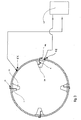
- baffles used for the insulation measure are as closest as possible, and therefore two adjacent baffles will be preferably selected, as symbolically showed in fig. 3.
- baffles are so construed and arranged to give a valid contribution to said measure and therefore they are split into two distinct groups, wherein the baffles of a first group are electrically connected among them, and the same thing for the baffles of the second group.
- baffles are grouped in a way that to a same group belong only baffles alternated each other on the inner surface of the drum, then the measure becomes more precise and stable as there is a greater probability that a part of the laundry is in the same time into contact with two adjacent baffles, that therefore have to belong to the two different groups, whereon the insulating resistance measure is taken out.
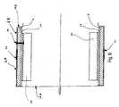
- a further metallic band 14 is overlapped, made for instance even in stainless steel, coated with copper or nickel etc., as exemplified in fig. 4, showing a front section of the drum wall orthogonal to the "X" drum axis, and in the fig. 5 showing the corresponding view of the drum as per the section B - B of fig. 4.
- Such further band 14 must then be wholly placed in close contact with said deadening band 6, but also under said insulating supports 2, 3, 4, 5 bearing the respective baffles, so as the previously existing situation, relevant to the electrical connections before described, will not be modified.
- the drum is no more visible from an user looking into the drum from outside the machine; therefore the drum can be made with a normal dull metal sheet, quite cheaper of the stainless steel sheet normally used.
- the instant improvement therefore takes advantage of such a very little distance "d” to turn the baffles on one side, and the metallic band 14 on the other side, into respective contacts of the measurement circuit of the insulation resistance inside the drum; to this purpose, and with reference to fig. 6, the instant improvement uses that metallic band 14 as one of the measure contact, and the baffles, one or more of them, and preferably all of them for obvious reasons, and connected among them, as the other measure contact.
- each of the baffles 20, 21, 22 and 23, that are selected as one common contact are linked with respective connections 20A, 20B, 20C, 20D able to electrically connect them to the first semi-drum 1A; the second contact is obtained by connecting the second semi-drum 1B to said metallic band 14 through a respective passing-through electric connection 30 (Fig. 7).
- Said connections 20A-20D are obviously insulated with respect to the surrounding elements, and preferably they can ordinarily cross the respective said supports 2-5 said metallic band 14 and said deadening band 6, and at last go into contact with said first semi-drum 1A; to its turn the connection 30 crosses said deadening band 6 and said metallic plate 14, and then connects to the respective semi-drum 1B.
- Fig. 7 symbolically illustrates such solution; said figure is a representation of the projection on a plane orthogonal to the drum axis "X" both of a portion of the semi-drum 1A, to which said connections 20A, 20B, 20C, 20D are terminated, and of a portion of the semi-drum 1B, (represented by the part contained in the curved lines "K" ) associated with said connection 30 linking it to said metallic band 14.
Landscapes
- Engineering & Computer Science (AREA)
- Textile Engineering (AREA)
- Detail Structures Of Washing Machines And Dryers (AREA)
- Drying Of Solid Materials (AREA)
- Control Of Washing Machine And Dryer (AREA)
Abstract
Description
- The instant invention refers to a kind of condenser drying machine, preferably of a household type, showing a particularly silent working during all times of drum operation.
- Largely known in the art is the general requirement of reducing as much as possible the noise generated by household appliances in their operation; such facts has been extensively described in the European Patent Application n. 04 100 491.2, filed by the same Applicant.
- During a drying cycle the laundry contained in the drum is continuously lifted to the inner top side of said drum due to the lifters rotation, and if the drum rotation speed is low enough the same laundry will fall down on the drum bottom, and then is again lifted with a repeating and uninterrupted motion.
- Also largely known in the art is the fact that the typical rumble of the laundry continuously falling down on the drum bottom is perceived as being particularly high, especially in the night time, since it is aggravated by the additional noise generated by the fans used to circulate the drying air, and possibly also by the condensing air passing through the condenser in such type of drying machines.
- This problem is particularly annoying when the drying machine operates at a slowed-down speed in order to reduce the noise generated by said air flows; as a matter of fact, during a slowed rotation and after having been lifted to the top, the laundry easier falls-down on the drum bottom, as the centrifugal force in the drum rotating at a lowered speed is no more enough to compensate the gravity force.
- In order to try to reduce such problem, from JP Application No. 06100806 it is known to fix a silencing sheet, made of insulating material, in contact with the internal circumferential metallic surface of the side plate of the rotary drum, and connecting the sheet to the side plate.
- However a further problem arises, when the laundry humidity is detected by electronic means that are able to measure the laundry insulating resistance between the drum and the baffles placed on the internal surface of the drum.
- In the fact the electric insulation generated by said sheet will prevent using the drum metallic surface as an electric contact, differently from the prior art drying machines where the laundry insulating resistance, depending on the relevant humidity, can be detected and measured.
- It would therefore be desirable, and is actually a main purpose of the present invention, to provide a clothes drying machine that will eliminate, or at least reduce the drawback of the noise produced by the laundry falling down on the drum bottom, without missing the possibility of using the drum as an electric contact area of insulation detection.
- According to another purpose of the present invention, this must be applicable also to drying machines whose drum is made of two electrically separated and cylindrical half-drums, according to a well known technique.
- According to a further purpose of the present invention this clothes drying machine shall be able to be easily manufactured using existing, ready available materials and techniques, and be competitive in its construction without suffering any alteration or reduction in the performance and reliability thereof.
- According to the present invention, these aims are reached in a drying machine incorporating the characteristics as recited in the appended claims and including such operating means as described below by mere way of non-limiting example with reference to the accompanying drawings, in which:
- Fig. 1 is a simplified sectional view of the drum of a dryer machine, seen from a section passing on the drum axis, according to the invention,
- Fig. 2 is a simplified sectional view of the corresponding drum, taken from section A - A of fig. 1,
- Fig. 3 is a schematic view of a drum showing an improvement of the invention, referred to the drum showed in fig. 2,
- Fig. 4 is a simplified sectional view of the drum of a dryer machine, seen from a section passing on the drum axis, according to a preferred embodiment of a different improvement of the invention,
- Fig. 5 is a simplified sectional view of the corresponding drum, taken from section B - B of fig. 4,
- Fig. 6 is a simplified sectional view of a drum according to a further improvement of the invention,
- Fig. 7 is a schematic and a symbolic view of a section of the drum according to fig. 6, taken from a section plane orthogonal to the drum axis.
- A laundry drying machine according to the prior art comprises:
- a rotating
drum 1, - a plurality of
baffles - means able to detect and measure the electric insulation resistance between said drum and said baffles connected among them.
- Furthermore said drying machine is also provided with a
deadening band 6, that covers the internal cylindrical surface of the drum and is interposed between it and the baffles, as showed in figures 1 and 2. - According to the invention, a plurality of insulating supports 2, 3, 4, 5, made preferably of plastic material, are mounted into contact with said internal surface of the drum, and said
baffles - Furthermore two
adjacent baffles respective contacts electric connections - These connections electrically link said baffles to respective and electrically separated portions A and B (here represented on the opposites bases of said drum).
- To these portions are then connected two sliding
electrical contacts measuring means 10, represented only symbolically as well known in the art. - A typical solution is to connect a drum base "A" to the
perimetral deadening band 6, and to use said sub-assembly constituted by said base and said band 6as a first point where to measure the insulation current, and to use the remaining base "B" as a second measuring point. - As clearly showed in fig. 3, said two
connections respective baffles drum wall 1, and through said deadeningband 6, and also through therespective supports - Of course said connections are insulated with respect to the outside, and especially with respect to the drum, in order to avoid the risk of shorting the baffles between which the insulating resistance has to be measured.
- In order to improve the precision and the stability of the measured insulation, it is also desirable that the baffles used for the insulation measure are as closest as possible, and therefore two adjacent baffles will be preferably selected, as symbolically showed in fig. 3.
- It will also easily understood that, in order to obtain the best measure precision and stability, all baffles are so construed and arranged to give a valid contribution to said measure and therefore they are split into two distinct groups, wherein the baffles of a first group are electrically connected among them, and the same thing for the baffles of the second group.
- It will be then apparent that the measure of the insulation resistance must be carried out between the two separate
sliding connections - Moreover it has to be remarked, as practically experienced, that if said baffles are grouped in a way that to a same group belong only baffles alternated each other on the inner surface of the drum, then the measure becomes more precise and stable as there is a greater probability that a part of the laundry is in the same time into contact with two adjacent baffles, that therefore have to belong to the two different groups, whereon the insulating resistance measure is taken out.
- However the proposed solution, although effective from the point of view of the requested result of a noise reduction, shows the "user unfriendly" drawback that the drum inner wall does not appear anymore shining and reflecting, as in the conventional drums made of stainless steel, but unavoidably shows the dull appearance of the deadening band.
- In order to avoid such problem, an advantageous improvement is here proposed; it consists in that on said deadening band a further
metallic band 14 is overlapped, made for instance even in stainless steel, coated with copper or nickel etc., as exemplified in fig. 4, showing a front section of the drum wall orthogonal to the "X" drum axis, and in the fig. 5 showing the corresponding view of the drum as per the section B - B of fig. 4. - Such
further band 14 must then be wholly placed in close contact with said deadeningband 6, but also under saidinsulating supports - With reference to the possible question of a consequent cost increase, it must be remarked that, as said
metallic band 14 is given only for aesthetic reasons, and not for mechanical and structural reasons, it can be made with a very thin thickness, so avoiding useless additional costs. - Furthermore in this case the drum is no more visible from an user looking into the drum from outside the machine; therefore the drum can be made with a normal dull metal sheet, quite cheaper of the stainless steel sheet normally used.
- As a conclusion the cost increase with the suggested solutions does result basically negligible.
- The possibility of using a metallic wall with sound damping properties is, in itself, known in the art; for instance the Company Thyssen-Stahl has developed a sandwich sheet, commercially known as TRITEC, that is a material comprising two metal outer "skins" and a viscoelastic plastic core layer.
- The just described solution allows a further advantageous improvement and an use broadening; indeed it has to be considered, as known in the art, that the electric signal derived from the baffles, and fmally measured, is as much stable and representative of the real laundry humidity as much the contacts of the measured signal are close to each other.
- In the just described solutions the measurement contacts are the adjacent baffles, and their distance is obviously remarkable.
- More over it is known that presently it is preferred to use metallic drums made with two corresponding and
semicilindrical semi-drums fitting element 15; each of saidsemi-drums - Such a solution is preferred for well known reasons that therefore will not be repeated.
- Do to the above, it was observed that when the described solution is used, that is the
metallic plate 14 is overlapped by thedeadening band 6, then the distance "d" between said plate and the baffles is due only to the thickness of said supports, of about 0,5 mm., that is a very smaller distance to the distance between adjacent baffles (see fig. 5). - The instant improvement therefore takes advantage of such a very little distance "d" to turn the baffles on one side, and the
metallic band 14 on the other side, into respective contacts of the measurement circuit of the insulation resistance inside the drum; to this purpose, and with reference to fig. 6, the instant improvement uses thatmetallic band 14 as one of the measure contact, and the baffles, one or more of them, and preferably all of them for obvious reasons, and connected among them, as the other measure contact. - To implement such purpose, each of the
baffles respective connections first semi-drum 1A; the second contact is obtained by connecting thesecond semi-drum 1B to saidmetallic band 14 through a respective passing-through electric connection 30 (Fig. 7). - Said
connections 20A-20D are obviously insulated with respect to the surrounding elements, and preferably they can ordinarily cross the respective said supports 2-5 saidmetallic band 14 and said deadeningband 6, and at last go into contact with saidfirst semi-drum 1A; to its turn theconnection 30 crosses said deadeningband 6 and saidmetallic plate 14, and then connects to therespective semi-drum 1B. - Fig. 7 symbolically illustrates such solution; said figure is a representation of the projection on a plane orthogonal to the drum axis "X" both of a portion of the
semi-drum 1A, to which saidconnections semi-drum 1B, (represented by the part contained in the curved lines "K" ) associated with saidconnection 30 linking it to saidmetallic band 14. - From said electrically insulated
semi-drums contacts
Claims (7)
- Laundry drying machine comprising:characterised in thata rotating drum (1),a deadening band (6) placed into contact on the cylindrical internal surface of said drum,a plurality of baffles (2A, 3A, 4A, 5A) placed inside said drum and near it,means able to detect the electric insulation between suitable points inside said drum,
a plurality of insulating supports (2, 3, 4, 5) placed against said deadening band is provided, said supports being able to carry respective said baffles (2A, 3A, 4A, 5A). - Machine according to claim 1, characterised in that said means are also comprising at least two baffles (2A, 3A) to which respective connections (7A, 8A) are associated, able to electrically connect said baffles to respective and reciprocally insulated two portions (A, B) placed on the outer surface of said drum.
- Machine according to claim 2, characterised in that the baffles linked to a first portion (A) of the drum are alternated to the baffles linked to the second drum portions (B).
- Machine according to any of the claims 2 or 3, characterised in that a further metallic band (14) is placed on said deadening band (6).
- Machine according to claim 4, characterised in that said supports (2, 3, 4, 5) are mounted on said metallic band (14).
- Laundry drying machine comprising:characterised in thata rotating drum (1) made of a first and of a second cylindrical and electrically insulated semi-drums (1A, 1B)a deadening band (6) placed into contact on the cylindrical internal surface of said drum,a plurality of baffles (2A, 3A, 4A, 5A) placed inside said drum and near it,means able to detect the electric insulation between suitable points inside said drum,a plurality of insulating supports (2, 3, 4, 5) placed against said deadening band is provided, said supports being able to carry a respective said baffle (2A, 3A, 4A, 5A),a further metallic band (14) is placed on said deadening band (6), said supports being mounted on and in contact with said metallic band (14).
- Machine according to claim 6, characterised in that:a plurality of electrical connections (20A, 20B, 20C, 20D) are provided between each or some of these baffles (2A, 3A, 4A, 5A) and a first semi-drum (1A),a separate connection (30) is provided between said further metallic band (14) and said second semi-drum (1B).
Priority Applications (5)
| Application Number | Priority Date | Filing Date | Title |
|---|---|---|---|
| AT04101157T ATE376090T1 (en) | 2004-03-19 | 2004-03-19 | HOUSEHOLD CLOTHES DRYER WITH IMPROVED DRUM |
| EP04101157A EP1577435B1 (en) | 2004-03-19 | 2004-03-19 | Household laundry dryer with improved drum |
| ES04101157T ES2291816T3 (en) | 2004-03-19 | 2004-03-19 | DRESSER OF DOMESTIC CLOTHING WITH IMPROVED DRUM. |
| DE602004009534T DE602004009534T2 (en) | 2004-03-19 | 2004-03-19 | Household clothes dryer with improved drum |
| PL04101157T PL1577435T3 (en) | 2004-03-19 | 2004-03-19 | Household laundry dryer with improved drum |
Applications Claiming Priority (1)
| Application Number | Priority Date | Filing Date | Title |
|---|---|---|---|
| EP04101157A EP1577435B1 (en) | 2004-03-19 | 2004-03-19 | Household laundry dryer with improved drum |
Publications (2)
| Publication Number | Publication Date |
|---|---|
| EP1577435A1 true EP1577435A1 (en) | 2005-09-21 |
| EP1577435B1 EP1577435B1 (en) | 2007-10-17 |
Family
ID=34833765
Family Applications (1)
| Application Number | Title | Priority Date | Filing Date |
|---|---|---|---|
| EP04101157A Expired - Lifetime EP1577435B1 (en) | 2004-03-19 | 2004-03-19 | Household laundry dryer with improved drum |
Country Status (5)
| Country | Link |
|---|---|
| EP (1) | EP1577435B1 (en) |
| AT (1) | ATE376090T1 (en) |
| DE (1) | DE602004009534T2 (en) |
| ES (1) | ES2291816T3 (en) |
| PL (1) | PL1577435T3 (en) |
Cited By (1)
| Publication number | Priority date | Publication date | Assignee | Title |
|---|---|---|---|---|
| EP3158124A4 (en) * | 2014-06-18 | 2018-01-03 | Owens Corning Intellectual Capital, LLC | Vibration damping system |
Citations (4)
| Publication number | Priority date | Publication date | Assignee | Title |
|---|---|---|---|---|
| GB1553841A (en) * | 1975-11-18 | 1979-10-10 | Ulgor Sci | Washing or drying machine including apparatus for controlling the degree of dampness of clothing |
| GB2184217A (en) * | 1985-12-17 | 1987-06-17 | Zanussi Elettrodomestici | Drum for a laundry dryer |
| DE19522432A1 (en) * | 1995-06-21 | 1997-01-02 | Miele & Cie | Laundry dryer with reduced cost and simplified assembly |
| DE19737340A1 (en) * | 1997-08-27 | 1999-03-04 | Aeg Hausgeraete Gmbh | Program-controlled electric laundry dryer |
-
2004
- 2004-03-19 AT AT04101157T patent/ATE376090T1/en not_active IP Right Cessation
- 2004-03-19 PL PL04101157T patent/PL1577435T3/en unknown
- 2004-03-19 EP EP04101157A patent/EP1577435B1/en not_active Expired - Lifetime
- 2004-03-19 ES ES04101157T patent/ES2291816T3/en not_active Expired - Lifetime
- 2004-03-19 DE DE602004009534T patent/DE602004009534T2/en not_active Expired - Lifetime
Patent Citations (4)
| Publication number | Priority date | Publication date | Assignee | Title |
|---|---|---|---|---|
| GB1553841A (en) * | 1975-11-18 | 1979-10-10 | Ulgor Sci | Washing or drying machine including apparatus for controlling the degree of dampness of clothing |
| GB2184217A (en) * | 1985-12-17 | 1987-06-17 | Zanussi Elettrodomestici | Drum for a laundry dryer |
| DE19522432A1 (en) * | 1995-06-21 | 1997-01-02 | Miele & Cie | Laundry dryer with reduced cost and simplified assembly |
| DE19737340A1 (en) * | 1997-08-27 | 1999-03-04 | Aeg Hausgeraete Gmbh | Program-controlled electric laundry dryer |
Non-Patent Citations (2)
| Title |
|---|
| PATENT ABSTRACTS OF JAPAN vol. 0140, no. 20 (C - 676) 17 January 1990 (1990-01-17) * |
| PATENT ABSTRACTS OF JAPAN vol. 1996, no. 02 29 February 1996 (1996-02-29) * |
Cited By (1)
| Publication number | Priority date | Publication date | Assignee | Title |
|---|---|---|---|---|
| EP3158124A4 (en) * | 2014-06-18 | 2018-01-03 | Owens Corning Intellectual Capital, LLC | Vibration damping system |
Also Published As
| Publication number | Publication date |
|---|---|
| PL1577435T3 (en) | 2008-03-31 |
| ATE376090T1 (en) | 2007-11-15 |
| DE602004009534T2 (en) | 2008-07-24 |
| ES2291816T3 (en) | 2008-03-01 |
| DE602004009534D1 (en) | 2007-11-29 |
| EP1577435B1 (en) | 2007-10-17 |
Similar Documents
| Publication | Publication Date | Title |
|---|---|---|
| CN105210296B (en) | Operating element and household appliance comprising the same | |
| KR20220153611A (en) | Induction rotor position sensor device, driving device | |
| JP2004344338A (en) | Washing machine | |
| CN106068043B (en) | Electromagnetic heating cooking system and power adjusting device thereof | |
| US20160196811A1 (en) | Electronic Cymbal With Multiple Detection Zones | |
| EP1961858B1 (en) | Laundry dryer | |
| EP1577435B1 (en) | Household laundry dryer with improved drum | |
| GB2157001A (en) | Weighing machine | |
| CN107574624B (en) | Device and method for detecting running balance of washing machine | |
| EP1895043B1 (en) | Control device for a laundry washing and/or drying machine | |
| EP2387642B1 (en) | A dryer comprising a dryness sensor | |
| ATE542943T1 (en) | ELECTRICAL SYNCHRONOUS MOTOR UNIT HAVING AN UNBALANCE DETECTION DEVICE | |
| US7679241B2 (en) | Vibration motor | |
| US7712337B2 (en) | Measuring device comprising an optical sensory array, and method using said measuring device | |
| WO2013098243A2 (en) | A household appliance | |
| EP1953291A1 (en) | Laundry treating machine with weight sensing means | |
| EP1914341B1 (en) | Drying machine | |
| US20210088361A1 (en) | Sensor device, operating device and household appliance having the operating device | |
| AU2005200314A1 (en) | Variable speed low-noise household clothes drying machine | |
| CN113584829B (en) | clothes dryer | |
| CN219908186U (en) | Clothes dryer assembly and clothes dryer | |
| JP2018038696A (en) | Drum washing machine | |
| CN120867056A (en) | Eccentric detection system and method for fixed-frequency washing machine | |
| JP2006105472A (en) | Cooker with touch keys | |
| JP2026508587A (en) | Clothes treatment device, clothes humidity detection method, and clothes dryness detection method |
Legal Events
| Date | Code | Title | Description |
|---|---|---|---|
| PUAI | Public reference made under article 153(3) epc to a published international application that has entered the european phase |
Free format text: ORIGINAL CODE: 0009012 |
|
| AK | Designated contracting states |
Kind code of ref document: A1 Designated state(s): AT BE BG CH CY CZ DE DK EE ES FI FR GB GR HU IE IT LI LU MC NL PL PT RO SE SI SK TR |
|
| AX | Request for extension of the european patent |
Extension state: AL LT LV MK |
|
| 17P | Request for examination filed |
Effective date: 20060120 |
|
| AKX | Designation fees paid |
Designated state(s): AT BE BG CH CY CZ DE DK EE ES FI FR GB GR HU IE IT LI LU MC NL PL PT RO SE SI SK TR |
|
| 17Q | First examination report despatched |
Effective date: 20060613 |
|
| GRAP | Despatch of communication of intention to grant a patent |
Free format text: ORIGINAL CODE: EPIDOSNIGR1 |
|
| GRAC | Information related to communication of intention to grant a patent modified |
Free format text: ORIGINAL CODE: EPIDOSCIGR1 |
|
| GRAS | Grant fee paid |
Free format text: ORIGINAL CODE: EPIDOSNIGR3 |
|
| GRAA | (expected) grant |
Free format text: ORIGINAL CODE: 0009210 |
|
| AK | Designated contracting states |
Kind code of ref document: B1 Designated state(s): AT BE BG CH CY CZ DE DK EE ES FI FR GB GR HU IE IT LI LU MC NL PL PT RO SE SI SK TR |
|
| REG | Reference to a national code |
Ref country code: GB Ref legal event code: FG4D |
|
| REG | Reference to a national code |
Ref country code: CH Ref legal event code: EP |
|
| REG | Reference to a national code |
Ref country code: IE Ref legal event code: FG4D |
|
| REF | Corresponds to: |
Ref document number: 602004009534 Country of ref document: DE Date of ref document: 20071129 Kind code of ref document: P |
|
| ET | Fr: translation filed | ||
| REG | Reference to a national code |
Ref country code: ES Ref legal event code: FG2A Ref document number: 2291816 Country of ref document: ES Kind code of ref document: T3 |
|
| REG | Reference to a national code |
Ref country code: PL Ref legal event code: T3 |
|
| NLV1 | Nl: lapsed or annulled due to failure to fulfill the requirements of art. 29p and 29m of the patents act | ||
| PG25 | Lapsed in a contracting state [announced via postgrant information from national office to epo] |
Ref country code: LI Free format text: LAPSE BECAUSE OF FAILURE TO SUBMIT A TRANSLATION OF THE DESCRIPTION OR TO PAY THE FEE WITHIN THE PRESCRIBED TIME-LIMIT Effective date: 20071017 Ref country code: CH Free format text: LAPSE BECAUSE OF FAILURE TO SUBMIT A TRANSLATION OF THE DESCRIPTION OR TO PAY THE FEE WITHIN THE PRESCRIBED TIME-LIMIT Effective date: 20071017 Ref country code: SE Free format text: LAPSE BECAUSE OF FAILURE TO SUBMIT A TRANSLATION OF THE DESCRIPTION OR TO PAY THE FEE WITHIN THE PRESCRIBED TIME-LIMIT Effective date: 20080117 Ref country code: NL Free format text: LAPSE BECAUSE OF FAILURE TO SUBMIT A TRANSLATION OF THE DESCRIPTION OR TO PAY THE FEE WITHIN THE PRESCRIBED TIME-LIMIT Effective date: 20071017 |
|
| REG | Reference to a national code |
Ref country code: CH Ref legal event code: PL |
|
| PG25 | Lapsed in a contracting state [announced via postgrant information from national office to epo] |
Ref country code: SI Free format text: LAPSE BECAUSE OF FAILURE TO SUBMIT A TRANSLATION OF THE DESCRIPTION OR TO PAY THE FEE WITHIN THE PRESCRIBED TIME-LIMIT Effective date: 20071017 Ref country code: BG Free format text: LAPSE BECAUSE OF FAILURE TO SUBMIT A TRANSLATION OF THE DESCRIPTION OR TO PAY THE FEE WITHIN THE PRESCRIBED TIME-LIMIT Effective date: 20080117 Ref country code: PT Free format text: LAPSE BECAUSE OF FAILURE TO SUBMIT A TRANSLATION OF THE DESCRIPTION OR TO PAY THE FEE WITHIN THE PRESCRIBED TIME-LIMIT Effective date: 20080317 |
|
| PG25 | Lapsed in a contracting state [announced via postgrant information from national office to epo] |
Ref country code: AT Free format text: LAPSE BECAUSE OF FAILURE TO SUBMIT A TRANSLATION OF THE DESCRIPTION OR TO PAY THE FEE WITHIN THE PRESCRIBED TIME-LIMIT Effective date: 20071017 |
|
| PG25 | Lapsed in a contracting state [announced via postgrant information from national office to epo] |
Ref country code: CZ Free format text: LAPSE BECAUSE OF FAILURE TO SUBMIT A TRANSLATION OF THE DESCRIPTION OR TO PAY THE FEE WITHIN THE PRESCRIBED TIME-LIMIT Effective date: 20071017 Ref country code: DK Free format text: LAPSE BECAUSE OF FAILURE TO SUBMIT A TRANSLATION OF THE DESCRIPTION OR TO PAY THE FEE WITHIN THE PRESCRIBED TIME-LIMIT Effective date: 20071017 |
|
| PLBE | No opposition filed within time limit |
Free format text: ORIGINAL CODE: 0009261 |
|
| STAA | Information on the status of an ep patent application or granted ep patent |
Free format text: STATUS: NO OPPOSITION FILED WITHIN TIME LIMIT |
|
| PG25 | Lapsed in a contracting state [announced via postgrant information from national office to epo] |
Ref country code: SK Free format text: LAPSE BECAUSE OF FAILURE TO SUBMIT A TRANSLATION OF THE DESCRIPTION OR TO PAY THE FEE WITHIN THE PRESCRIBED TIME-LIMIT Effective date: 20071017 Ref country code: BE Free format text: LAPSE BECAUSE OF FAILURE TO SUBMIT A TRANSLATION OF THE DESCRIPTION OR TO PAY THE FEE WITHIN THE PRESCRIBED TIME-LIMIT Effective date: 20071017 Ref country code: RO Free format text: LAPSE BECAUSE OF FAILURE TO SUBMIT A TRANSLATION OF THE DESCRIPTION OR TO PAY THE FEE WITHIN THE PRESCRIBED TIME-LIMIT Effective date: 20071017 |
|
| 26N | No opposition filed |
Effective date: 20080718 |
|
| PG25 | Lapsed in a contracting state [announced via postgrant information from national office to epo] |
Ref country code: MC Free format text: LAPSE BECAUSE OF NON-PAYMENT OF DUE FEES Effective date: 20080331 |
|
| PG25 | Lapsed in a contracting state [announced via postgrant information from national office to epo] |
Ref country code: EE Free format text: LAPSE BECAUSE OF FAILURE TO SUBMIT A TRANSLATION OF THE DESCRIPTION OR TO PAY THE FEE WITHIN THE PRESCRIBED TIME-LIMIT Effective date: 20071017 Ref country code: IE Free format text: LAPSE BECAUSE OF NON-PAYMENT OF DUE FEES Effective date: 20080319 Ref country code: GR Free format text: LAPSE BECAUSE OF FAILURE TO SUBMIT A TRANSLATION OF THE DESCRIPTION OR TO PAY THE FEE WITHIN THE PRESCRIBED TIME-LIMIT Effective date: 20080118 |
|
| PG25 | Lapsed in a contracting state [announced via postgrant information from national office to epo] |
Ref country code: FI Free format text: LAPSE BECAUSE OF FAILURE TO SUBMIT A TRANSLATION OF THE DESCRIPTION OR TO PAY THE FEE WITHIN THE PRESCRIBED TIME-LIMIT Effective date: 20071017 |
|
| PG25 | Lapsed in a contracting state [announced via postgrant information from national office to epo] |
Ref country code: CY Free format text: LAPSE BECAUSE OF FAILURE TO SUBMIT A TRANSLATION OF THE DESCRIPTION OR TO PAY THE FEE WITHIN THE PRESCRIBED TIME-LIMIT Effective date: 20071017 |
|
| PG25 | Lapsed in a contracting state [announced via postgrant information from national office to epo] |
Ref country code: LU Free format text: LAPSE BECAUSE OF NON-PAYMENT OF DUE FEES Effective date: 20080319 Ref country code: HU Free format text: LAPSE BECAUSE OF FAILURE TO SUBMIT A TRANSLATION OF THE DESCRIPTION OR TO PAY THE FEE WITHIN THE PRESCRIBED TIME-LIMIT Effective date: 20080418 |
|
| PG25 | Lapsed in a contracting state [announced via postgrant information from national office to epo] |
Ref country code: TR Free format text: LAPSE BECAUSE OF FAILURE TO SUBMIT A TRANSLATION OF THE DESCRIPTION OR TO PAY THE FEE WITHIN THE PRESCRIBED TIME-LIMIT Effective date: 20071017 |
|
| PGFP | Annual fee paid to national office [announced via postgrant information from national office to epo] |
Ref country code: DE Payment date: 20130321 Year of fee payment: 10 Ref country code: GB Payment date: 20130321 Year of fee payment: 10 Ref country code: ES Payment date: 20130314 Year of fee payment: 10 Ref country code: FR Payment date: 20130408 Year of fee payment: 10 |
|
| PGFP | Annual fee paid to national office [announced via postgrant information from national office to epo] |
Ref country code: PL Payment date: 20130225 Year of fee payment: 10 |
|
| PGFP | Annual fee paid to national office [announced via postgrant information from national office to epo] |
Ref country code: IT Payment date: 20130327 Year of fee payment: 10 |
|
| REG | Reference to a national code |
Ref country code: DE Ref legal event code: R119 Ref document number: 602004009534 Country of ref document: DE |
|
| GBPC | Gb: european patent ceased through non-payment of renewal fee |
Effective date: 20140319 |
|
| REG | Reference to a national code |
Ref country code: FR Ref legal event code: ST Effective date: 20141128 |
|
| REG | Reference to a national code |
Ref country code: DE Ref legal event code: R119 Ref document number: 602004009534 Country of ref document: DE Effective date: 20141001 |
|
| PG25 | Lapsed in a contracting state [announced via postgrant information from national office to epo] |
Ref country code: GB Free format text: LAPSE BECAUSE OF NON-PAYMENT OF DUE FEES Effective date: 20140319 Ref country code: FR Free format text: LAPSE BECAUSE OF NON-PAYMENT OF DUE FEES Effective date: 20140331 Ref country code: DE Free format text: LAPSE BECAUSE OF NON-PAYMENT OF DUE FEES Effective date: 20141001 |
|
| PG25 | Lapsed in a contracting state [announced via postgrant information from national office to epo] |
Ref country code: IT Free format text: LAPSE BECAUSE OF NON-PAYMENT OF DUE FEES Effective date: 20140319 |
|
| PG25 | Lapsed in a contracting state [announced via postgrant information from national office to epo] |
Ref country code: PL Free format text: LAPSE BECAUSE OF NON-PAYMENT OF DUE FEES Effective date: 20140319 |
|
| REG | Reference to a national code |
Ref country code: PL Ref legal event code: LAPE |
|
| PG25 | Lapsed in a contracting state [announced via postgrant information from national office to epo] |
Ref country code: ES Free format text: LAPSE BECAUSE OF NON-PAYMENT OF DUE FEES Effective date: 20140320 |