EP1577188B1 - Moving body system - Google Patents
Moving body system Download PDFInfo
- Publication number
- EP1577188B1 EP1577188B1 EP05003062A EP05003062A EP1577188B1 EP 1577188 B1 EP1577188 B1 EP 1577188B1 EP 05003062 A EP05003062 A EP 05003062A EP 05003062 A EP05003062 A EP 05003062A EP 1577188 B1 EP1577188 B1 EP 1577188B1
- Authority
- EP
- European Patent Office
- Prior art keywords
- detected
- moving
- vehicle
- moving body
- path
- Prior art date
- Legal status (The legal status is an assumption and is not a legal conclusion. Google has not performed a legal analysis and makes no representation as to the accuracy of the status listed.)
- Expired - Fee Related
Links
Images


Classifications
-
- B—PERFORMING OPERATIONS; TRANSPORTING
- B61—RAILWAYS
- B61L—GUIDING RAILWAY TRAFFIC; ENSURING THE SAFETY OF RAILWAY TRAFFIC
- B61L27/00—Central railway traffic control systems; Trackside control; Communication systems specially adapted therefor
- B61L27/04—Automatic systems, e.g. controlled by train; Change-over to manual control
-
- B—PERFORMING OPERATIONS; TRANSPORTING
- B61—RAILWAYS
- B61L—GUIDING RAILWAY TRAFFIC; ENSURING THE SAFETY OF RAILWAY TRAFFIC
- B61L23/00—Control, warning, or like safety means along the route or between vehicles or vehicle trains
- B61L23/002—Control or safety means for heart-points and crossings of aerial railways, funicular rack-railway
- B61L23/005—Automatic control or safety means for points for operator-less railway, e.g. transportation systems
-
- B—PERFORMING OPERATIONS; TRANSPORTING
- B61—RAILWAYS
- B61L—GUIDING RAILWAY TRAFFIC; ENSURING THE SAFETY OF RAILWAY TRAFFIC
- B61L25/00—Recording or indicating positions or identities of vehicles or vehicle trains or setting of track apparatus
- B61L25/02—Indicating or recording positions or identities of vehicles or vehicle trains
- B61L25/026—Relative localisation, e.g. using odometer
-
- G—PHYSICS
- G01—MEASURING; TESTING
- G01D—MEASURING NOT SPECIALLY ADAPTED FOR A SPECIFIC VARIABLE; ARRANGEMENTS FOR MEASURING TWO OR MORE VARIABLES NOT COVERED IN A SINGLE OTHER SUBCLASS; TARIFF METERING APPARATUS; MEASURING OR TESTING NOT OTHERWISE PROVIDED FOR
- G01D5/00—Mechanical means for transferring the output of a sensing member; Means for converting the output of a sensing member to another variable where the form or nature of the sensing member does not constrain the means for converting; Transducers not specially adapted for a specific variable
- G01D5/12—Mechanical means for transferring the output of a sensing member; Means for converting the output of a sensing member to another variable where the form or nature of the sensing member does not constrain the means for converting; Transducers not specially adapted for a specific variable using electric or magnetic means
- G01D5/244—Mechanical means for transferring the output of a sensing member; Means for converting the output of a sensing member to another variable where the form or nature of the sensing member does not constrain the means for converting; Transducers not specially adapted for a specific variable using electric or magnetic means influencing characteristics of pulses or pulse trains; generating pulses or pulse trains
- G01D5/245—Mechanical means for transferring the output of a sensing member; Means for converting the output of a sensing member to another variable where the form or nature of the sensing member does not constrain the means for converting; Transducers not specially adapted for a specific variable using electric or magnetic means influencing characteristics of pulses or pulse trains; generating pulses or pulse trains using a variable number of pulses in a train
- G01D5/2454—Encoders incorporating incremental and absolute signals
- G01D5/2455—Encoders incorporating incremental and absolute signals with incremental and absolute tracks on the same encoder
- G01D5/2457—Incremental encoders having reference marks
Definitions
- the present invention relates to a moving body system that moves a moving body along a moving path.
- a known automated guided vehicle system is used in a semiconductor manufacturing plant or the like, and in the automated guided vehicle system, a moving path is laid along processing devices and the like. An automated guided vehicle is caused to run automatically on the moving path to convey work pieces. The automated guided vehicle needs to be precisely stopped in front of a processing device.
- the automated guided vehicle system is configured as described below.
- Figure 14 is a diagram generally showing the configuration of a conventional automated guided vehicle system.
- Processing devices 104, 104, ... are arranged along a running path 102 of an automated guided vehicle 101.
- Stop position marks 120 are stuck to respective stop positions of the vehicle 101 which correspond to the processing devices 104, 104, ... and the like.
- the vehicle 101 is provided with a marker detecting sensor 115 to detect the stop position markers 120.
- a running program is constructed in which acceleration and deceleration timings and the like are written, and running of the vehicle 101 is then controlled in accordance with the running program.
- An encoder is provided on a rotating shaft of wheels of the vehicle 101. Output pulses from the encoder are counted to calculate the distance that the vehicle 101 has run.
- the vehicle 101 nears the target processing device 104, it starts to be decelerated (see Figure 14A), and the speed is sufficiently reduced so that the vehicle 101 runs at an about-to-stop speed at which it can stop immediately at any time (see Figure 14B).
- the marker detecting sensor 115 detects the leading end of the stop position marker 120 at the destination (see Figure 14C).
- the counting of output pulses from the encoder is then restarted.
- the marker detecting sensor 115 reaches the center of the stop position marker 120 in its longitudinal direction, the wheels of the vehicle 101 are stopped (see Figure 14D).
- the stop control of the vehicle 101 is performed as described above to precisely stop the vehicle 101 at the destination.
- the wheels of the vehicle 101 may slip on the running path 102.
- a slip is likely to occur when the vehicle 101 is accelerated or decelerated.
- the slip there may be a difference between the running distance obtained by accumulating the output pulses from the encoder and the actual running distance.
- the vehicle 101 starts to decelerate prematurely.
- the vehicle 101 then reaches the about-to-stop speed considerably before the destination.
- the vehicle 101 then carries out creep running at the about-to-stop speed until it reaches the destination.
- such an approach requires a long time, resulting in a serious time loss. This disadvantageously degrades the workability of the system.
- a large number of markers 220, 220, ... are stuck to and along a running path 202 of a vehicle 201.
- the markers 220, 220, ... are stuck not only to positions corresponding to processing devices 204, 204, ... but also to the positions between the processing devices 204.
- the vehicle 201 is provided with a marker detecting sensor 215 that detects the markers 220.
- speed control is performed in accordance with the running path 202.
- the speed and a deceleration start position are controlled on the basis of the distance to the stop position 208.
- the vehicle 201 runs at a speed specified by a running program until it detects the marker 220 at the position 207 immediately before the stop position 208 corresponding to the destination.
- the marker detecting sensor 215 of the vehicle 201 detects the trailing end of the position 207 immediately before the stop position 208.
- a pulse count value in an encoder provided on a rotating shaft of wheels of the vehicle 201 is preset to zero. That is, the trailing end of the marker 220 is used as a reference position for the pulse counting executed by the encoder.
- speed control is performed while counting output pulses from the encoder to calculate the running distance of the vehicle 201 from the marker 220 at the position 207 immediately before the stop position 208.
- the vehicle 201 then reaches the deceleration start position, which is preset to allow the vehicle 201 to stop precisely at the stop position 208.
- deceleration control is performed to obtain a predetermined deceleration.
- the vehicle 201 nears the target stop position 208 and detects the leading end of the marker 220 provided at the stop position 208.
- the pulse count value in the encoder is preset again.
- the stop control of the vehicle 201 is started at the point where the leading end of the marker 220 at the stop position 208 is detected.
- the counting of pulses by the encoder is restarted at the leading end of the marker 220 at the stop position 208.
- Control is performed such that the running speed of the vehicle 201 is further reduced, while accumulating the running distance of the vehicle 201.
- the wheels of the vehicle 201 are stopped at the position where the marker detecting sensor 215 detects the trailing end of the marker 220 at the stop position 208.
- the vehicle 201 is thus precisely stopped at the stop position.
- the vehicle 201 can thus be controllably stopped only at the stop positions 208, 208, ...
- the vehicle 201 is stopped at other positions, such problems as associated with the former conventional technique may occur.
- the markers 220, 220, ... must be repositioned.
- the newly attached markers 220, 220, ... must be taught to the vehicle 201.
- the vehicle 201 must be experimentally operated to check whether or not it can stop precisely at the positions of the markers 220, 220, ... This checking operation requires much time and effort and is cumbersome. This is another problem to be solved.
- the present invention provides a moving body system comprising a moving body that moves along a moving path and a detected member laid along the moving path, wherein the detected member comprises a plurality of mark members in a direction in which the moving body moves and the moving body comprises detecting means for detecting the mark members of the detected member, wherein each of the mark members comprises a detected portion that can be detected by the detecting means and a non-detected portion that is not detected by the detecting means, wherein the detected member is configured like comb teeth in which a comb tooth portion is the detected portion, while a void between the comb teeth is the non-detected portion, wherein the width of the detected portion in the moving direction of the moving body is equal to that of the non-detected portion in the moving direction of the moving body, wherein the detecting means comprises first detecting means and second detecting means arranged in the moving direction of the moving body, and wherein a moving path of the moving body has a branching portion that branches to at least two paths, and
- the present invention provides a moving body system comprising a moving body that moves' along a moving path and a detected member laid along the moving path, wherein the detected member comprises a plurality of mark members in a direction in which the moving body moves and the moving body comprises detecting means for detecting the mark members of the detected member, wherein each of the mark members comprises a detected portion that can be detected by the detecting means and a non-detected portion that is not detected by the detecting means, wherein the detected member is configured like comb teeth in which a comb tooth portion is the detected portion, while a void between the comb teeth is the non-detected portion, wherein the width of the detected portion in the moving direction of the moving body is equal to that of the non-detected portion in the moving direction of the moving body, wherein the detecting means comprises first detecting means and second detecting means arranged in the moving direction of the moving body, and wherein a moving path of the moving body has a joining portion in which at least two paths are
- the detected members have positional information, and the detecting means read the positional information from the detected members.
- the moving body comprises an encoder that measures a moving distance and control means for controlling the moving speed of the moving body by determining a moving position while using the detecting means to detect the mark members of the detected member until the mark member of the detected member located immediately before a stop target position is reached, the control means then using, between the mark member located immediately before the stop target position and the stop target position, the encoder to measure the moving distance from the mark member located immediately before the stop target position, the control means then stopping the moving body at the stop target position.
- control means resets the measurement of the moving distance by the encoder to an origin every time the detecting member detects a detecting point on the mark member of the detected member.
- the moving body uses the detecting means to detect the mark members of the detected member laid along the moving path. Consequently, the moving position of the moving body can be substantially precisely determined wherever on the moving path the moving body is. This avoids the situation in which there is a difference between the actual moving distance and the moving distance determined by the moving body and in which the vehicle thus starts to decelerate prematurely and starts to run at an about-to-stop speed considerably before the stop position.
- the moving body can also move fast to the stop position.
- the moving body system thus has an improved workability.
- the second detecting means of the moving body detects the second detected member. This makes it possible to check into which moving path the moving body has advanced. The moving body system is thus more reliable.
- the second detecting means of the moving body detects the third detected member. This makes it possible to confirm that the moving body has passed the joining portion.
- the moving body system is thus more reliable.
- the detecting means of the moving body detects positional information on the detected member to check whether or not the detecting means has failed to detect any part of the detected member. If the detecting means should fail to detect any part of the detected member, corrections will be made to improve the reliability of the moving body system.
- the moving speed of the moving body is controlled by using the detecting member to detect the mark members of the detected member to roughly determine the moving position of the moving body.
- the encoder is used to measure the moving distance from the mark member immediately before the stop target position.
- the moving body is precisely stopped at the stop target position.
- the moving body can also move fast to the stop position.
- the moving body system thus has an improved workability. Further, with this configuration, the moving body can be precisely stopped at any position on the path. The moving body system is thus more convenient.
- the control means resets the measurement of the moving distance by the encoder to the origin. This makes it possible to carry out measurement of the moving distance without being affected by errors from previous operations. The moving body system is thus more reliable.
- a moving body system according to the present invention will be described below with reference to an automated guided vehicle system by way of example.
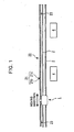
- Figure 1 generally shows the configuration of the automated guided vehicle system.
- running rails 2, 2 are laid as a moving path of an automated guided vehicle 1.
- Processing devices 4, 4, ... and the like are arranged along the running rails 2, 2.
- a detected member 20 is also laid along the running rails 2.
- the vehicle 1 running on the running rails 2, 2 determines its own running position while detecting the detected member 20.
- the detected member 20 is placed outside one 2 of the running rails 2, 2.
- the detected member 20 may be placed between the running rails 2, 2 or installed above the running rails 2, 2.
- the arrangement of the detected member 20 is not particularly limited provided that it is extended along the moving path of the vehicle 1.
- the detected member 20 is provided with a large number of mark members 21, 21, ... in a direction in which the vehicle 1 moves.
- Each of the mark members 21 comprises a detected portion 21b that can be detected by detecting means of the vehicle 1 and a non-detected portion 21c that is not detected by the detecting means.
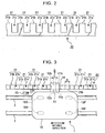
- Figure 2 shows an example of the detected member 20.
- the detected member 20 is configured like comb teeth. A comb tooth portion constitutes the detected portion 21b, and the gap between the comb teeth constitutes the non-detected portion 21c. In the moving direction of the vehicle 1, the width of the detected portion 21b is equal to that of the non-detected portion 21c.
- the distance from an ON signal obtained when detecting means described later detects one end of the detected portion 21b to an OFF signal obtained when the detecting means detects the other end of the detected portion 21b (one end of the non-detected portion 21c) is the same as the distance from an OFF signal obtained when the detecting means detects the other end of the detected portion 21b (one end of the non-detected portion 21c) to an ON signal obtained when the detecting means detects one end of the adjacent detected portion 21b (the other end of the non-detected portion 21c).
- the moving distance can thus be determined simply by counting the number of ON and OFF signals.
- the detected member 20 is not limited to the comb tooth configuration but may be shaped like a ladder laid on the ground.
- the configuration of the detected member is not particularly limited.
- the vehicle 1 which is a moving body, has a main body 1B supported by front wheels 19F, 19F and rear wheels 19R, 19R.
- the vehicle 1 has a four-wheel drive configuration in order to suppress slips.
- Driving sources 18F, 18R are mounted on the front wheels 19F, 19F and the rear wheels 19R, 19R, respectively (see Figure 5).
- the driving sources 18F, 18R are composed of, for example, servo motors that can rotated in a forward and backward directions. The vehicle 1 can thus be moved forward and backward.
- Figure 5 shows the control configuration of the vehicle 1.
- a controller 10 is mounted on the vehicle 1 to control the running of the vehicle and the transfer of loads.
- the controller 10 connects communicatively to a running control section 16F that controls the driving source 18F of the front wheels 19F, 19F and to a running control section 16R that controls the driving source 18R of the rear wheels 19R, 19R.
- Encoders 17F, 17R are mounted on driving shafts of the driving sources 18F, 18R, respectively, to measure the moving distance of the vehicle 1.
- the encoders 17F, 17R are communicatively connected to the controller 10. While the vehicle 1 is in motion, the encoders 17F, 17R, which are rotation speed detecting means, detect the rotation speeds of the wheels 19F, 19F, 19R, 19R.
- the controller 10 which is control means, refers to measured values from the encoder 17R (or 17F) of the driving source 18R (or 18F) of the wheels 19R, 19R (or 19F, 19F) located in the rear of the vehicle 1 in the advancing direction.
- the controller 10 refers to measured values from the encoder 17F (or 17R) of the driving source 18F (or 18R) of the wheels 19F, 19F (or 19R, 19R) located in the front of the vehicle 1 in the advancing direction.
- the controller 10 determines the moving speed or the moving distance on the basis of the measured values from the encoder 17R (or 17F) of the driving source 18R (or 18F) of the rear wheels 19R, 19R (or 19F, 19F).
- the controller 10 determines the moving speed or the moving distance on the basis of the measured values from the encoder 17F (or 17R) of the driving source 18F (or 18R) of the rear wheels 19F, 19F (or 19R, 19R).
- the controller 10 determines the moving speed or the moving distance on the basis of the measured values from the encoder 17R (or 17F) of the driving source 18R (or 18F) of the rear wheels 19R, 19R (or 19F, 19F).
- the controller 10 may determine the moving speed or the moving distance on the basis of the measured values from the encoder 17F (or 17R) of the driving source 18F (or 18R) of the rear wheels 19F, 19F (or 19R, 19R).
- the above configuration enables the controller 10 to switch to the encoder 17F/17R corresponding to the wheels 19F, 19F or 19R, 19R which are unlikely to slip, depending on whether the vehicle 1 accelerates or decelerates.
- the controller 10 more precisely measures the moving speed or the moving distance.
- the moving body system is thus more reliable.
- the controller 10 determines a torque used to drive the wheels 19F, 19F and a torque used to drive the wheels 19R, 19R.
- the controller 10 outputs torque instruction values to the running control sections 16F, 16R.
- the running control section 16F (16R) then controls the torque of the driving source 18F (18R) on the basis of the torque instruction value.
- the torque instruction values for the running control sections 16F, 16R are determined so as to minimize the slip of the wheels 19F, 19F, 19R, 19R on the running rails 2, 2.
- the torque instruction value for the running control section 16R (or 16F) corresponding to the wheels 19R, 19R (or 19F, 19F) located in the rear in the advancing direction and on which the gravity acts is set larger than that for the running control section 16F (or 16R) corresponding to the front wheels 19F, 19F (or 19R, 19R).
- the torque instruction value for the running control section 16F (or 16R) corresponding to the wheels 19F, 19F (or 19R, 19R) located in the front in the advancing direction and on which the gravity acts is set larger than that for the running control section 16R (or 16F) corresponding to the rear wheels 19R, 19R (or 19F, 19F).
- the torque instruction value for the running control section 16F corresponding to the wheels 19F, 19F is set equal to that for the running control section 16R corresponding to the wheels 19R, 19R.
- the ratio of the torque instruction value for the running control section 16F (or 16R) corresponding to the wheels 19F, 19F (or 19R, 19R) located in the front in the advancing direction to the torque instruction value for the running control section 16R (or 16F) corresponding to the wheels 19R, 19R (or 19F, 19F) located in the rear is set at 4 to 6 for acceleration, 6 to 4 for deceleration, or 5 to 5 for equal-speed running.
- the ratio of the torque values is not limited to the fixed values but may be varied on the basis of a rotation speed from the encoder 17F or 17R.
- Figure 3 is a plan view showing the configuration of the vehicle 1.
- a bracket 14 is attached to a side of the vehicle 1.
- the bracket 14 is provided with detecting means for detecting the mark members 21, 21, ... of the detected member 20.
- the detecting means are comprised of a first detecting sensor 11 and a second detecting sensor 12.
- Each detecting sensor 11 (12) is composed of a photosensor comprising a light emitting element 11a (12a) and a light receiving element 11b (12b).
- the bracket 14 appears like the letter U turned upside down in a front view.
- the detected member 20 is located in the space enclosed by the letter U turned upside down.
- the light emitting elements 11a, 12a are attached to one (inner) vertical area of the bracket 14 via the space.
- the light receiving elements 11b, 12b are attached to the other (outer) vertical area.
- the first detecting sensor 11 and the second detecting sensor 12 are arranged in the moving direction of the vehicle 1.
- the spacing W between the first detecting sensor 11 and the second detecting sensor 12 is half the width D [mm] of the detected portion 21b of the detected member 20 in the moving direction of the vehicle 1 (see Figure 3).
- the spacing W between the first detecting sensor 11 and the second detecting sensor 12 is set so as to meet the relation shown below.
- the light emitting element 11a (12a) of each detecting sensor 11 (12) emits a light beam to the light receiving element 11b (12b).
- the light beam is blocked and then unblocked every time the vehicle 1 moves to cause the detecting sensor 11 (12) to pass the detected portions 21b, 21b, ... of the detected member 20.
- the detecting sensor 11 (12) when the detecting sensor 11 (12) reaches one end of the detecting sensor 11 (12), the light beam from the light emitting element 11a (12a) to the light receiving element 11b (12b) is blocked to output an OFF signal to the controller 10.
- the detecting sensor 11 (12) passes the other end of the detected portion 21b to reach the non-detected portion 21c, the light receiving element 11b (12b) receives the light beam from the light emitting element 11a (12a) to output an ON signal to the controller 10. In this manner, the detecting sensor 11 (12) intermittently outputs the ON/OFF signal to the controller 10.
- the controller 10 also comprises an address counter that counts the number of ON and OFF signals from the detecting sensors 11, 12 (see Figure 8).
- the controller 10 roughly determines the moving position of the vehicle I on the basis of the number of signals counted by the address counter. This operation will be described in brief.
- addresses are assigned to the detected portions 21b, 21b, ... and non-detected portions 21c, 21c, ... of the mark members 21, 21, ... of the detected member 20 with reference to the detected portion 21b or non-detected portion 21c of a certain mark member 21.
- the addresses are consecutive from one to the other end of the detected member 20 in its longitudinal direction.
- the controller 10 counts the number of ON and OFF signals from the detecting sensors 11, 12 to determine which address has been reached by the vehicle.
- the controller 10 determines the moving position of the vehicle 1 on the basis of the address determined. The assignment of the addresses will be described later in detail.
- the controller 10 can use the first detecting sensor 11 and second detecting sensor 12, arranged in parallel in the moving direction of the vehicle 1, to determine the moving direction of the vehicle 1. Specifically, if the first detecting sensor 11 detects a certain detected portion 21b (or non-detected portion 21c) on the detected member 20 earlier than the second detecting sensor 12, the controller 10 determines that the vehicle 1 is moving forward. In contrast, if the second detecting sensor 12 detects the certain detected portion 21b (or non-detected portion 21c) on the detected member 20 earlier than the first detecting sensor 11, the controller 10 determines that the vehicle 1 is moving backward.
- a plurality of detected members 23, 23, ... are arranged along the running rails 2, which are the moving paths of the vehicle 1 (see Figure 1).
- a detecting device 13 is provided at the bottom of the vehicle 1 to detect the detected members 23, 23, ...
- the detected members 23, 23, ... are arranged at predetermined intervals in association with the addresses on the detected member 20.
- the detected members 23 are arranged outside one 2 of the running rails 2, 2.
- the detected members 23 may be arranged between the running rails 2, 2.
- the arrangement of the detected members 23 is not particularly limited provided that they are arranged along the path of the vehicle 1.
- a bar code 23b is stuck to each of the detected members 23 and indicates positional information on the position of the detected member 23.
- the detecting device 13, mounted on the vehicle 1, reads the bar codes 23b, 23b, ... of the detected members 23, 23, ... to determine a passing point.
- the detected members 23, 23, ... are not limited to the bar codes, and RFID tags or the like may be stuck to the detected members 23.
- addresses are assigned to four positions including the opposite ends and center of the detected portion 21b and the center of the non-detected portion 21c in the moving direction of the vehicle 1.
- the combination of the first detecting sensor 11 and second detecting sensor 12 detects the four addresses of each mark member 21 and then outputs a corresponding detection signal to the controller 10.
- the controller 10 uses the address counter to count the addresses to roughly determine the moving position of the vehicle 1.
- the spacing between the first detecting sensor 11 and the second detecting sensor 12 is half the width of the detected portion 21b (or non-detected portion 21c) of the detected member 20 in the moving direction of the vehicle 1.
- the two detecting sensors 11, 12 detect each mark member 21 of the detected member 20 as described below.
- the vehicle 1 is in motion, and at a first detecting point, the first detecting sensor 11 detects one end of the detected portion 21b of the mark member 21 (see Figure 7A). At the first detecting point, the first detecting sensor 11 outputs an ON signal to the address counter of the controller 10. Then, at a second detecting point, the second detecting sensor 12 detects the one end of the detected portion 21b of the mark member 21 (see Figure 7B). At the second detecting point, the first detecting sensor 11 is located in the center of the detected portion 21b. The second detecting sensor 12 outputs an ON signal to the address counter of the controller 10.
- the first detecting sensor 11 detects the other end of the detected portion 21b of the mark member 21 (see Figure 7C).
- the first detecting sensor 11 outputs an OFF signal to the address counter of the controller 10.
- the second detecting sensor 12 detects the other end of the detected portion 21b of the mark member 21 (see Figure 7D).
- the first detecting sensor 11 is located in the center of the non-detected portion 21c.
- the second detecting sensor 12 outputs an OFF signal to the address counter of the controller 10.
- the address counter of the controller 10 detects the four detecting points of each mark member 21 on the basis of the combination of the first detecting sensor 11 and second detecting sensor 12. The addresses are assigned to the respective four detecting points.
- the encoder 17F (17R) is configured to output signals for N pulses (N is a natural number) between the addresses.
- the encoder 17F (17R) is also configured to measure the moving distance of the vehicle 1 by diving the space between the addresses into N pieces. Simply speaking, as shown in Figure 6, (N-1) graduations are assigned to the space between the addresses. The space between the addresses is interpolated by the graduations.
- the encoder 17F (17R) counts the number of graduations between the spaces to accurately determine the moving position of the vehicle 1.
- the distance between the addresses is 10 [mm].
- the encoder 17F (17R) is configured to output signals for 1,000 pulses between the addresses, that is, to be able to measure the moving distance of the vehicle 1 on the order of 0.01 [mm] .
- Figure 8 shows a positional information counter provided in the controller 10 of the vehicle 1.
- the positional information counter comprises an address counter and a graduation counter.
- the last three digits are a value input by the encoder 17F (17R) and indicate the count number of a graduation between the addresses.
- the fourth and subsequent digits from the last are a value input by the detecting sensors 11, 12 and indicate the count number of an address.
- An address is set using the combination of the count number of the address and the count number of the graduation between the addresses.
- the address shown in Figure 8 indicates the 395th graduation of the address 120.
- the address indicates that the vehicle 1 is 1203.95 [mm] from a reference point. This is one of the absolute addresses provided along the detected member 20. In connection with the stop control of the vehicle 1, the vehicle 1 can be stopped at an arbitrary position on the detected member 20 by specifying the address.
- the controller 10 of the vehicle 1 is also configured to reset the measurement of the moving distance by the encoder 17F (17R) to an origin every time the detecting sensor 11 or detecting sensor 12 detects the address of the mark member 21 of the detected member 20.
- the measurement of the moving distance is thus carried out without being affected by errors from previous operations. This makes the moving body system more reliable.
- the graduation counter is reset to the origin "000". Further, the address counter is incremented by one during forward movement and decremented by one during backward movement.
- the controller 10 determines the moving position on the basis of the absolute address regardless of the moving direction of the vehicle 1.
- a running program is constructed in which acceleration and deceleration timings and the like are written.
- the running of the vehicle 1 is then controlled in accordance with the running program.
- the controller 10 of the vehicle 1 detects the addresses of the mark members 21, 21, ... of the detected member 20 to roughly determine the moving position.
- the controller 10 thus controls the moving speed of the vehicle 1 on the basis of the detected moving position.
- the detecting device 13, provided in the vehicle detects positional information on the detected members 23 dotted along the running rails 2, 2. The controller thus checks whether or not the detecting sensor 11 or detecting sensor 12 has failed to detect any address.
- the deceleration control of the vehicle 1 is performed on the detected address. As the vehicle 1 nears the stop target position, it is decelerated so that it reaches an about-to-stop speed at the detecting point between the address to which the stop target position belongs and the preceding address. The about-to-stop speed is such that the vehicle 1 can be immediately stopped at any time. Between the preceding address and the stop target position, the vehicle 1 uses the encoder 17F (17R) to measure the moving distance from this address at small increments on the order of 0.01 [mm]. Thus, the vehicle 1 is controllably stopped precisely at the stop target position.
- the above configuration avoids the situation in which there is a difference between the actual moving distance and the moving distance determined by the vehicle 1 and in which the vehicle thus starts to decelerate prematurely and starts to run at the about-to-stop speed considerably before the stop position.
- the vehicle 1 can move fast to the stop target position.
- the moving body system thus has an improved workability.
- the controller 10 of the vehicle 1 can substantially accurately determine its moving position at any position on the moving path.
- the vehicle 1 can thus be precisely stopped at any position on the moving path. This makes the moving body system more convenient.
- the moving path of the vehicle 1 which is a moving body, is composed of a linear moving path.
- the moving path of the vehicle 1 is not limited to the linear moving path.
- the moving path may include a curved portion.
- the moving path of the vehicle 1 may be configured to have a branching or joining portion. In this case, the moving path is configured as described below.
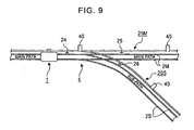
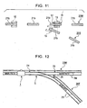
- Figure 9 shows a branching portion (or joining portion) on the moving path of the vehicle 1.
- Running rails 2M, 2M are laid along a main path, whereas running rails 2S, 2S are laid along a sub-path.
- the branching portion 5 is provided with a switching member (not shown in the drawings) that switches the moving path of the vehicle 1 between the main path and the sub-path.
- the vehicle 1 itself may be provided with switching means for switching the moving path.
- the moving path is configured as described below.
- a guide rail along the main path and a guide rail along the sub-path are provided before and after the branching portion 5.
- the guide rails are arranged parallel immediately before the branching portion 5.
- the vehicle 1 is provided with a branching device comprising a guide roller selectively applied to the guide rail of the main path or the guide rail of the sub-path.
- the paired branching devices are provided in the front and rear of the vehicle 1 in its moving direction.
- the paired branching devices and the guide rails constitute the switching means.
- Each branching device comprises three guide rollers each having an axis corresponding to a vertical direction.
- the branching device is placed so that a central guide roller rolls and passes between the two guide rollers, arranged parallel with each other immediately before the branching portion.
- the central guide roller is fixed, and the guide rollers on the opposite sides of the central guide roller can be freely elevated and lowered in the vertical direction.
- the vehicle 1 elevates (or lowers) and sets one of the rollers at the same height as that of the central guide roller.
- the guide rail of the main path or the guide rail of the sub-path is sandwiched between the above guide roller and the central guide roller. Consequently, the vehicle 1 is guided along the guide rail and can thus select its own moving path.
- a detected member 24 is provided immediately before the branching portion 5 and along the running rail 2M of the main path.
- the main path and the sub-path are provided with detected members 25, 26, respectively, along their running rails 2M, 2S (or 2T).
- the detected members 24, 25, 26 are provided for a purpose different from that for the detected members 23, 23, ...
- the detected members 24, 25, 26 are provided to allow determination as to whether the vehicle 1 is running on the main path or the sub-path after passing the branching portion 5.
- the detecting means for detecting the detected members 23, 23, ... is composed of the same detecting device 13 as that constituting the detecting means for detecting the detected members 24, 25, 26, in order to reduce the number of parts required.
- these detecting means may be composed of separate detecting means.
- Bar codes or RFID tags are stuck to the detected members 24, 25, 26, the bar codes or RFID tags indicating positional information on the positions of the detected members 24, 25, 26.
- the detecting device 13 reads path information from the detected members 24, 25, 26 to determine the moving path on which the vehicle is running.
- a detected member 20M is provided along the running rail 2M.
- a detected member 20S is provided along the running rail 2S.
- Each of the detected members 20M, 20S is provided with the large number of mark members 21, 21, ... in the moving direction of the vehicle 1.
- Each mark member 21 comprises a detected portion 21b that can be detected by the detecting sensors 11, 12 of the vehicle 1 and a non-detected portion 21c that is not detected by the detecting sensors 11, 12 (see Figure 2).
- the detected members 20M, 20S are connected together at the branching portion 5.
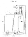
- the running rails 2M, 2M of the main path interfere with the detected member 20S of the sub-path. Accordingly, as shown in Figure 9 and Figure 10, the running rails 2M, 2M, 2S, 2S are laid on a floor surface.
- the detected members 20M, 20S are installed above the vehicle 1.
- the running rails 2M, 2M of the main path cross the detected member 20S of the sub-path at different levels.
- Poles 40, 40, ... are installed along the running rail 2M (or 2S) at predetermined intervals so as to extend in the vertical direction.
- An arm portion 40a is provided at an upper end of each of the poles 40 to support the detected member 20M (or 20S).
- the arm portion 40a projects from the pole main body toward the running rails 2M, 2M (or 2S, 2S).
- the detected member 20M (or 20S) hangs from the arm portion 40a. In this case, the detected member 20M (or 20S) is turned upside down compared to the configuration in Figure 2 so that the comb teeth face downward.
- a support member 9 is attached to an upper end of one side of the vehicle 1.
- a bracket 15 is mounted on the support member 9.
- the bracket 15 is obtained by turning the bracket 14 upside down so that it appears like the letter "U” in a front view.
- the bracket 15 is fixedly placed on a top surface of the vehicle 1 so that it appears like the letter "U” in a front view.
- the length of the bracket 15 in the moving direction of the vehicle 1 is about half of the width D of the detected portion 21b of the detected member 20M (or 20S) in the moving direction of the vehicle 1.
- the first detecting sensor 11 and the second detecting sensor 12 are attached to the opposite ends of the bracket 15 in the moving direction of the vehicle 1.
- the remaining part of the configuration of the vehicle 1 is similar to that of the above configuration, which does not have any branching potion 5. Thus, its description is omitted.
- the bracket 15 of the vehicle 1 does not interfere with the detected portion 21b of the detected member 20S (or 20M) on the path opposite to the one into which the vehicle I advances, as shown in Figure 11.
- the detected member 20T placed along the running rail 2S of the sub-path, may be configured as shown in Figure 12.
- the detected member 20T is also configured similarly to the detected member 20.
- the detected member 2T is not connected to the detected member 20M, placed along the running rail 2M of the main path.
- the leading end of end of the detected member 2T (in the joining portion, the trailing end) is placed outside the running rails 2M, 2M of the main path.
- the detected member 20T of the sub-path is thus configured so as not to cross the running rails 2M, 2M of the main path. Accordingly, with this configuration, the detected members 20M, 20T can be laid on the floor surface together with the running rails 2M, 2M, 2S, 2S.
- the vehicle 1 can be configured as shown in Figure 4. With this configuration, the length, in the moving direction of the vehicle 1, of the bracket 14 to which the first detecting sensor 11 and the second detecting sensor 12 are attached need not be small compared to the bracket 15.
- the spacing W between the first detecting sensor 11 and the second detecting sensor 12 may be set so as to satisfy the above relation.
- the stop control of the vehicle 1 is not performed. If the vehicle 1 is to be stopped in a section of the running rails 2S, 2S of the sub-path which section is located after the branch and in which the detected member 2T is not placed, the following operation is performed only in this section: output pulses from the encoder 17R (or 17F) start to be accumulated when the detecting device 13, mounted on the vehicle 1, detects the detected member 24 placed immediately before the branching portion 5.
- the stop control is not performed in this section and the vehicle 1 advances from the branching portion 5 into the sub-path, the following operation is performed: when the detecting device 13 detects the detected member 26 placed near the leading end of the detected member 20T, the combination of detection of the mark members of the detected member 20T and detection of output pulses from the encoder 17F (or 17R) is started. This allows the determination of the current position of the vehicle on the sub-path.
- a similar process is also executed if the vehicle 1 runs to the joining portion 5. If the vehicle 1 runs leftward in Figure 12 and is to be stopped in a section of the running rails 2S, 2S of the sub-path which section is located immediately before the joining portion 5 and in which the detected member 2T is not place, the following operation is performed only in this section: when the vehicle 1 running along the sub-path uses the detecting device 13 to detect the detected member 26 placed immediately before the joining portion 5, output pulses from the encoder 17R (or 17F) start to be accumulated to perform stop control.
- the stop control is not performed in this section and the vehicle 1 advances from the sub-path through the joining portion 5 into the main path, when the detecting device 13 detects the detected member 24 placed immediately after the junction, the address counter of the positional information counter is switched to the address corresponding to the main path. This will be described later in detail.
- the controller 10 of the vehicle 1 is already provided with a running instruction. Accordingly, the vehicle 1 itself already knows which path to take at the branching portion 5. However, a process described below is used to confirm that the vehicle 1 has surely advanced into the path to be taken.
- the controller 10 of the vehicle 1 recognizes that the vehicle 1 has reached the branching portion 5. Then, the next detected member detected by the detecting device 13 allows the controller 10 to determine along which of the main path and the sub-path the vehicle I is running. Specifically, when the detecting device 13 detects the detected member 25, the controller 10 recognizes that the vehicle 1 is running along the main path. On the other hand, when the detecting device 13 detects the detected member 26, the controller 10 recognizes that the vehicle 1 is running along the sub-path.
- controller 10 of the vehicle 1 is adapted to uniquely determine the current position of the vehicle 1 on the system on the basis of the combination of detection of the mark members 21 of the detected members 20M, 20S or (20T) and detection of the detected members 24, 25, 26.
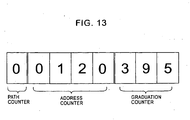
- Figure 13 shows the positional information counter provided in the controller 10 of the vehicle 1.
- the positional information counter comprises a path counter in addition to the address counter and the graduation counter.
- the last three digits correspond to the graduation counter and indicate an input value from the encoder 17F (or 17R) which is the count number of a graduation between addresses.
- the fourth to seventh digits from the last correspond to the address counter and indicate an input value from the detecting sensors 11, 12 which is the count number of an address.
- the first digit corresponds to the path counter and indicates the moving path along which the vehicle 1 is running.
- the path counter displays numerical values or the like which correspond to the respective paths. For example, “0" indicates that the vehicle 1 is running along the main path, “1” indicates that the vehicle 1 is running along a first sub-path branched from the main path, and “2" indicates that the vehicle 1 is running along a second sub-path branched from the main path.
- the display in the path counter is switched when the detecting device 13 of the vehicle 1 detects the detected member 24, 25, 26 in the branching portion 5 (or joining portion).
- the path counter displays a numerical value indicating the path into which the vehicle 1 is to advance after passing the branching portion 5. That is, if the vehicle 1 running along the main path is to continue to run on the main path after passing the branching portion 5, the path counter displays "0". If the vehicle 1 is to advance into the sub-path after passing the branching portion 5, the path counter displays " 1".
- the detecting device 13 of the vehicle 1 detects the detected member 25 or detected member 26 of the path into which the vehicle 1 is to advance, the numerical value displayed in the path counter and indicating path information is established.
- the vehicle 1 should advance into a path different from the expected one after passing the branching portion 5, then when the detecting device 13 of the vehicle 1 detects the detected member 25 or detected member 26 of the path different from the expected one, the numerical value displayed in the path counter and indicating path information will be changed to one corresponding to the path different from the expected one.
- the vehicle 1 runs to the joining portion 5. Then, if the vehicle 1 runs leftward in Figure 9, when the detecting device 13 detects the detected member 25 or 26, the controller 10 of the vehicle 1 recognizes that the vehicle 1 is to reach the joining portion 5. Then, when the detecting device 13 detects the detected member 24, the controller 10 recognizes that the vehicle 1 has passed the joining portion 5.
- the path counter displays a numerical value corresponding to the path taken by the vehicle 1 after the junction (in Figure 9, the main path).
- the address counter displays an address corresponding to the path taken by the vehicle 1 after the junction. For example, if the vehicle 1 advances from the sub-path into the main path, the path counter of the positional information counter displays a numerical value corresponding to the sub-path.
- the address counter displays an address corresponding to the sub-path.
- the path counter of the positional information counter is switched to a numeral value corresponding to the main path. Further, the address counter is switched to an address corresponding to the main path.
- the moving path of the vehicle 1 branches to two paths or two paths are joined together to form one path.
- the moving body system is similarly configured if the path of the vehicle 1 branches to three paths or if three paths are joined together to form one path.
- the controller 10 of the vehicle 1 uniquely determines the current position of the vehicle 1 on the moving body system on the basis of the combination of detection of the mark members 21 of the detected members 20M, 20S or (20T), detection of the detected members 24, 25, 26, and detection of output pulses from the encoder 17F (or 17R).
- the present invention is applicable to a moving body system in which the moving body moves in the vertical direction or obliquely upward or downward along a slope.
- the moving direction of the moving body is not particularly limited.
Description
- The present invention relates to a moving body system that moves a moving body along a moving path.
- A known automated guided vehicle system is used in a semiconductor manufacturing plant or the like, and in the automated guided vehicle system, a moving path is laid along processing devices and the like. An automated guided vehicle is caused to run automatically on the moving path to convey work pieces. The automated guided vehicle needs to be precisely stopped in front of a processing device. The automated guided vehicle system is configured as described below.
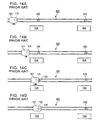
- Figure 14 is a diagram generally showing the configuration of a conventional automated guided vehicle system.
Processing devices path 102 of an automated guidedvehicle 101.Stop position marks 120 are stuck to respective stop positions of thevehicle 101 which correspond to theprocessing devices vehicle 101 is provided with amarker detecting sensor 115 to detect thestop position markers 120. - When a destination (any of the
processing devices 104 or the like) for thevehicle 101 is specified, a running program is constructed in which acceleration and deceleration timings and the like are written, and running of thevehicle 101 is then controlled in accordance with the running program. An encoder is provided on a rotating shaft of wheels of thevehicle 101. Output pulses from the encoder are counted to calculate the distance that thevehicle 101 has run. As thevehicle 101 nears thetarget processing device 104, it starts to be decelerated (see Figure 14A), and the speed is sufficiently reduced so that thevehicle 101 runs at an about-to-stop speed at which it can stop immediately at any time (see Figure 14B). Then, themarker detecting sensor 115 detects the leading end of thestop position marker 120 at the destination (see Figure 14C). - The counting of output pulses from the encoder is then restarted. When the
marker detecting sensor 115 reaches the center of thestop position marker 120 in its longitudinal direction, the wheels of thevehicle 101 are stopped (see Figure 14D). The stop control of thevehicle 101 is performed as described above to precisely stop thevehicle 101 at the destination. - However, during running, the wheels of the
vehicle 101 may slip on the runningpath 102. In particular, a slip is likely to occur when thevehicle 101 is accelerated or decelerated. When the slip occurs, there may be a difference between the running distance obtained by accumulating the output pulses from the encoder and the actual running distance. As a result, thevehicle 101 starts to decelerate prematurely. Thevehicle 101 then reaches the about-to-stop speed considerably before the destination. Thevehicle 101 then carries out creep running at the about-to-stop speed until it reaches the destination. However, such an approach requires a long time, resulting in a serious time loss. This disadvantageously degrades the workability of the system. - Thus, in view of this problem, the Unexamined
Japanese Patent Application Publication (Tokkai) No. 2002-351541 - As shown in Figure 15, a large number of
markers path 202 of avehicle 201. Themarkers processing devices processing devices 204. Thevehicle 201 is provided with amarker detecting sensor 215 that detects themarkers 220. Before thevehicle 201 reaches themarker 220 located at a position immediately before atarget stop position 208, speed control is performed in accordance with the runningpath 202. Between theposition 207 and thestop position 208, the speed and a deceleration start position are controlled on the basis of the distance to thestop position 208. - When a destination (any of the
processing devices 204 or the like) is specified, thevehicle 201 runs at a speed specified by a running program until it detects themarker 220 at theposition 207 immediately before thestop position 208 corresponding to the destination. As shown in Figure 15A, themarker detecting sensor 215 of thevehicle 201 detects the trailing end of theposition 207 immediately before thestop position 208. Then, a pulse count value in an encoder provided on a rotating shaft of wheels of thevehicle 201 is preset to zero. That is, the trailing end of themarker 220 is used as a reference position for the pulse counting executed by the encoder. Then, speed control is performed while counting output pulses from the encoder to calculate the running distance of thevehicle 201 from themarker 220 at theposition 207 immediately before thestop position 208. Thevehicle 201 then reaches the deceleration start position, which is preset to allow thevehicle 201 to stop precisely at thestop position 208. Then, deceleration control is performed to obtain a predetermined deceleration. - As shown in Figure 15B, the
vehicle 201 nears thetarget stop position 208 and detects the leading end of themarker 220 provided at thestop position 208. - Then, the pulse count value in the encoder is preset again. The stop control of the
vehicle 201 is started at the point where the leading end of themarker 220 at thestop position 208 is detected. Thus, the counting of pulses by the encoder is restarted at the leading end of themarker 220 at thestop position 208. Control is performed such that the running speed of thevehicle 201 is further reduced, while accumulating the running distance of thevehicle 201. Then, as shown in Figure 15C, the wheels of thevehicle 201 are stopped at the position where themarker detecting sensor 215 detects the trailing end of themarker 220 at thestop position 208. Thevehicle 201 is thus precisely stopped at the stop position. - With the latter conventional technique (the Unexamined
Japanese Patent Application Publication (Tokkai) No. 2002-351541 stop position 208 and the position immediately before thestop position 208. Accordingly, there is only a small difference between the actual running distance and the running distance obtained by accumulating output pulses from the encoder on the basis of the detection of the trailing end of themarker 220 at theposition 207. This substantially avoids the disadvantageous situation in which thevehicle 201 starts to decelerate prematurely and in which it thus takes thevehicle 201 too long a time to reach the destination, as in the case of the conventional technique. Thevehicle 201 can also move fast between theposition 207 and thestop position 208. Further, thevehicle 201 can be precisely stopped at thestop position 208. - However, the
vehicle 201 can thus be controllably stopped only at thestop positions vehicle 201 is stopped at other positions, such problems as associated with the former conventional technique may occur. - Moreover, when the layout of the automated guided vehicle system is changed or new facilities are added to the system, the
markers - Furthermore, the newly attached
markers vehicle 201. Thevehicle 201 must be experimentally operated to check whether or not it can stop precisely at the positions of themarkers - The document
U.S. 5,235,181 discloses a positioning system with detected members, which have a comb teeth configuration, together with markers identifying the absolute position of the vehicle. - In view of these problems, it is an object of the present invention to provide a moving body system which makes it possible to determine the moving position of a moving body such as a vehicle or a stacker crane wherever on a moving path the moving body is and which enables the moving body to stop precisely at any position, the moving body system also enabling the moving body to move fast to the stop position, the moving body system also enabling the moving body to stop at a precise position even if the moving path has a branching portion or a joining portion.
- A description has been given of the problems to be solved by the present invention. Now, the description will be given of means for solving the problems.
- As set forth in
Claim 1, the present invention provides a moving body system comprising a moving body that moves along a moving path and a detected member laid along the moving path, wherein the detected member comprises a plurality of mark members in a direction in which the moving body moves and the moving body comprises detecting means for detecting the mark members of the detected member, wherein each of the mark members comprises a detected portion that can be detected by the detecting means and a non-detected portion that is not detected by the detecting means, wherein the detected member is configured like comb teeth in which a comb tooth portion is the detected portion, while a void between the comb teeth is the non-detected portion, wherein the width of the detected portion in the moving direction of the moving body is equal to that of the non-detected portion in the moving direction of the moving body, wherein the detecting means comprises first detecting means and second detecting means arranged in the moving direction of the moving body, and
wherein a moving path of the moving body has a branching portion that branches to at least two paths, and a second detected member is provided on each of the branching paths, while the moving body is provided with second detecting means for detecting the second detected member. - Further, as set forth in
Claim 2, the present invention provides a moving body system comprising a moving body that moves' along a moving path and a detected member laid along the moving path, wherein the detected member comprises a plurality of mark members in a direction in which the moving body moves and the moving body comprises detecting means for detecting the mark members of the detected member, wherein each of the mark members comprises a detected portion that can be detected by the detecting means and a non-detected portion that is not detected by the detecting means, wherein the detected member is configured like comb teeth in which a comb tooth portion is the detected portion, while a void between the comb teeth is the non-detected portion, wherein the width of the detected portion in the moving direction of the moving body is equal to that of the non-detected portion in the moving direction of the moving body, wherein the detecting means comprises first detecting means and second detecting means arranged in the moving direction of the moving body, and
wherein a moving path of the moving body has a joining portion in which at least two paths are joined together, and a third detected member is provided on a resulting path so that the second detecting means can sense the third detected member. - Furthermore, as set forth in
Claim 3, the detected members have positional information, and the detecting means read the positional information from the detected members. - Moreover, as set forth in
Claim 4, the moving body comprises an encoder that measures a moving distance and control means for controlling the moving speed of the moving body by determining a moving position while using the detecting means to detect the mark members of the detected member until the mark member of the detected member located immediately before a stop target position is reached, the control means then using, between the mark member located immediately before the stop target position and the stop target position, the encoder to measure the moving distance from the mark member located immediately before the stop target position, the control means then stopping the moving body at the stop target position. - Finally, as set forth in
Claim 5, the control means resets the measurement of the moving distance by the encoder to an origin every time the detecting member detects a detecting point on the mark member of the detected member. - First, with the aspect of the invention set forth in
Claim 1, the moving body uses the detecting means to detect the mark members of the detected member laid along the moving path. Consequently, the moving position of the moving body can be substantially precisely determined wherever on the moving path the moving body is. This avoids the situation in which there is a difference between the actual moving distance and the moving distance determined by the moving body and in which the vehicle thus starts to decelerate prematurely and starts to run at an about-to-stop speed considerably before the stop position. The moving body can also move fast to the stop position. The moving body system thus has an improved workability. Further, after the moving body has passed the branching portion, the second detecting means of the moving body detects the second detected member. This makes it possible to check into which moving path the moving body has advanced. The moving body system is thus more reliable. - With the aspect of the present invention set forth in
Claim 2, after the moving body has passed the joining portion, the second detecting means of the moving body detects the third detected member. This makes it possible to confirm that the moving body has passed the joining portion. The moving body system is thus more reliable. - Further, with the aspect of the present invention set forth in
Claim 3, the detecting means of the moving body detects positional information on the detected member to check whether or not the detecting means has failed to detect any part of the detected member. If the detecting means should fail to detect any part of the detected member, corrections will be made to improve the reliability of the moving body system. - Furthermore, with the aspect of the present invention set forth in
Claim 4, before the moving body reaches the mark member immediately before the stop target position, the moving speed of the moving body is controlled by using the detecting member to detect the mark members of the detected member to roughly determine the moving position of the moving body. Between the mark member immediately before the stop target position and the stop target position, the encoder is used to measure the moving distance from the mark member immediately before the stop target position. Thus, the moving body is precisely stopped at the stop target position. This configuration avoids the situation in which there is a difference between the actual moving distance and the moving distance determined by the moving body and in which the vehicle thus starts to decelerate prematurely and starts to run at the about-to-stop speed considerably before the stop position. The moving body can also move fast to the stop position. The moving body system thus has an improved workability. Further, with this configuration, the moving body can be precisely stopped at any position on the path. The moving body system is thus more convenient. - Moreover, with the aspect of the present invention set forth in
Claim 5, every time the detecting means detects the detecting point on the mark member of the detected member, the control means resets the measurement of the moving distance by the encoder to the origin. This makes it possible to carry out measurement of the moving distance without being affected by errors from previous operations. The moving body system is thus more reliable. - A moving body system according to the present invention will be described below with reference to an automated guided vehicle system by way of example.
- Figure 1 generally shows the configuration of the automated guided vehicle system. In a clean room of a semiconductor manufacturing plant or the like, running
rails vehicle 1.Processing devices rails member 20 is also laid along the running rails 2. Thevehicle 1 running on the runningrails member 20. According to the present embodiment, the detectedmember 20 is placed outside one 2 of the runningrails member 20 may be placed between the runningrails rails member 20 is not particularly limited provided that it is extended along the moving path of thevehicle 1. - The detected
member 20 is provided with a large number ofmark members vehicle 1 moves. Each of themark members 21 comprises a detectedportion 21b that can be detected by detecting means of thevehicle 1 and anon-detected portion 21c that is not detected by the detecting means. Figure 2 shows an example of the detectedmember 20. The detectedmember 20 is configured like comb teeth. A comb tooth portion constitutes the detectedportion 21b, and the gap between the comb teeth constitutes thenon-detected portion 21c. In the moving direction of thevehicle 1, the width of the detectedportion 21b is equal to that of thenon-detected portion 21c. With this configuration, the distance from an ON signal obtained when detecting means described later detects one end of the detectedportion 21b to an OFF signal obtained when the detecting means detects the other end of the detectedportion 21b (one end of thenon-detected portion 21c) is the same as the distance from an OFF signal obtained when the detecting means detects the other end of the detectedportion 21b (one end of thenon-detected portion 21c) to an ON signal obtained when the detecting means detects one end of the adjacent detectedportion 21b (the other end of thenon-detected portion 21c). This simplifies a control configuration. The moving distance can thus be determined simply by counting the number of ON and OFF signals. The detectedmember 20 is not limited to the comb tooth configuration but may be shaped like a ladder laid on the ground. The configuration of the detected member is not particularly limited. - Now, the
vehicle 1 will be described. - As shown in Figures 3 and 4, the
vehicle 1, which is a moving body, has amain body 1B supported byfront wheels rear wheels vehicle 1 has a four-wheel drive configuration in order to suppress slips. Drivingsources front wheels rear wheels sources vehicle 1 can thus be moved forward and backward. - Figure 5 shows the control configuration of the
vehicle 1. Acontroller 10 is mounted on thevehicle 1 to control the running of the vehicle and the transfer of loads. Thecontroller 10 connects communicatively to a runningcontrol section 16F that controls the drivingsource 18F of thefront wheels control section 16R that controls the drivingsource 18R of therear wheels Encoders driving sources vehicle 1. Theencoders controller 10. While thevehicle 1 is in motion, theencoders wheels vehicle 1 accelerates or runs at an equal speed, thecontroller 10, which is control means, refers to measured values from theencoder 17R (or 17F) of the drivingsource 18R (or 18F) of thewheels vehicle 1 in the advancing direction. When thevehicle 1 decelerates, thecontroller 10 refers to measured values from theencoder 17F (or 17R) of the drivingsource 18F (or 18R) of thewheels vehicle 1 in the advancing direction. - This is because during acceleration, gravity acts on the
wheels vehicle 1 in the advancing direction to cause thefront wheels front wheels rails controller 10 determines the moving speed or the moving distance on the basis of the measured values from theencoder 17R (or 17F) of the drivingsource 18R (or 18F) of therear wheels wheels vehicle 1 in the advancing direction to cause therear wheels rear wheels rails controller 10 determines the moving speed or the moving distance on the basis of the measured values from theencoder 17F (or 17R) of the drivingsource 18F (or 18R) of therear wheels - According to the present embodiment, during movement at an equal speed, the
controller 10 determines the moving speed or the moving distance on the basis of the measured values from theencoder 17R (or 17F) of the drivingsource 18R (or 18F) of therear wheels controller 10 may determine the moving speed or the moving distance on the basis of the measured values from theencoder 17F (or 17R) of the drivingsource 18F (or 18R) of therear wheels controller 10 to switch to theencoder 17F/17R corresponding to thewheels vehicle 1 accelerates or decelerates. Thus, thecontroller 10 more precisely measures the moving speed or the moving distance. The moving body system is thus more reliable. - Further, depending on whether the
vehicle 1 accelerates or decelerates, thecontroller 10 determines a torque used to drive thewheels wheels controller 10 outputs torque instruction values to the runningcontrol sections control section 16F (16R) then controls the torque of the drivingsource 18F (18R) on the basis of the torque instruction value. The torque instruction values for the runningcontrol sections wheels rails vehicle 1 accelerates, the torque instruction value for the runningcontrol section 16R (or 16F) corresponding to thewheels control section 16F (or 16R) corresponding to thefront wheels vehicle 1 decelerates, the torque instruction value for the runningcontrol section 16F (or 16R) corresponding to thewheels control section 16R (or 16F) corresponding to therear wheels control section 16F corresponding to thewheels control section 16R corresponding to thewheels - For example, the ratio of the torque instruction value for the running
control section 16F (or 16R) corresponding to thewheels control section 16R (or 16F) corresponding to thewheels encoder - Figure 3 is a plan view showing the configuration of the
vehicle 1. Abracket 14 is attached to a side of thevehicle 1. Thebracket 14 is provided with detecting means for detecting themark members member 20. The detecting means are comprised of a first detectingsensor 11 and a second detectingsensor 12. Each detecting sensor 11 (12) is composed of a photosensor comprising alight emitting element 11a (12a) and alight receiving element 11b (12b). - As shown in Figure 4, the
bracket 14 appears like the letter U turned upside down in a front view. The detectedmember 20 is located in the space enclosed by the letter U turned upside down. Thelight emitting elements bracket 14 via the space. Thelight receiving elements sensor 11 and the second detectingsensor 12 are arranged in the moving direction of thevehicle 1. The spacing W between the first detectingsensor 11 and the second detectingsensor 12 is half the width D [mm] of the detectedportion 21b of the detectedmember 20 in the moving direction of the vehicle 1 (see Figure 3). In general, when the width of the detectedportion 21b is defined as D, the spacing W between the first detectingsensor 11 and the second detectingsensor 12 is set so as to meet the relation shown below.
- In the above configuration, the
light emitting element 11a (12a) of each detecting sensor 11 (12) emits a light beam to thelight receiving element 11b (12b). The light beam is blocked and then unblocked every time thevehicle 1 moves to cause the detecting sensor 11 (12) to pass the detectedportions member 20. - Specifically, when the detecting sensor 11 (12) reaches one end of the detecting sensor 11 (12), the light beam from the
light emitting element 11a (12a) to thelight receiving element 11b (12b) is blocked to output an OFF signal to thecontroller 10. When the detecting sensor 11 (12) passes the other end of the detectedportion 21b to reach thenon-detected portion 21c, thelight receiving element 11b (12b) receives the light beam from thelight emitting element 11a (12a) to output an ON signal to thecontroller 10. In this manner, the detecting sensor 11 (12) intermittently outputs the ON/OFF signal to thecontroller 10. - The
controller 10 also comprises an address counter that counts the number of ON and OFF signals from the detectingsensors 11, 12 (see Figure 8). Thecontroller 10 roughly determines the moving position of the vehicle I on the basis of the number of signals counted by the address counter. This operation will be described in brief. As shown in Figure 6, addresses are assigned to the detectedportions non-detected portions mark members member 20 with reference to the detectedportion 21b ornon-detected portion 21c of acertain mark member 21. The addresses are consecutive from one to the other end of the detectedmember 20 in its longitudinal direction. Thecontroller 10 counts the number of ON and OFF signals from the detectingsensors controller 10 then determines the moving position of thevehicle 1 on the basis of the address determined. The assignment of the addresses will be described later in detail. - Further, the
controller 10 can use the first detectingsensor 11 and second detectingsensor 12, arranged in parallel in the moving direction of thevehicle 1, to determine the moving direction of thevehicle 1. Specifically, if the first detectingsensor 11 detects a certain detectedportion 21b (ornon-detected portion 21c) on the detectedmember 20 earlier than the second detectingsensor 12, thecontroller 10 determines that thevehicle 1 is moving forward. In contrast, if the second detectingsensor 12 detects the certain detectedportion 21b (ornon-detected portion 21c) on the detectedmember 20 earlier than the first detectingsensor 11, thecontroller 10 determines that thevehicle 1 is moving backward. - Moreover, a plurality of detected
members rails 2, which are the moving paths of the vehicle 1 (see Figure 1). - A detecting
device 13 is provided at the bottom of thevehicle 1 to detect the detectedmembers members member 20. According to the present embodiment, the detectedmembers 23 are arranged outside one 2 of the runningrails members 23 may be arranged between the runningrails members 23 is not particularly limited provided that they are arranged along the path of thevehicle 1. - A
bar code 23b is stuck to each of the detectedmembers 23 and indicates positional information on the position of the detectedmember 23. The detectingdevice 13, mounted on thevehicle 1, reads thebar codes members members members 23. Alternatively, it is possible to stick nothing to the detectedmembers 23 and to cause the detectingdevice 12 to only detect the detectedmembers members controller 10 is counted to determined the passing point. - Now, the addresses on the detected
member 20 will be described. - As shown in Figure 6, in each of the
mark members 21 of the detectedmember 20, addresses are assigned to four positions including the opposite ends and center of the detectedportion 21b and the center of thenon-detected portion 21c in the moving direction of thevehicle 1. The combination of the first detectingsensor 11 and second detectingsensor 12 detects the four addresses of eachmark member 21 and then outputs a corresponding detection signal to thecontroller 10. Thecontroller 10 uses the address counter to count the addresses to roughly determine the moving position of thevehicle 1. - As previously described, the spacing between the first detecting
sensor 11 and the second detectingsensor 12 is half the width of the detectedportion 21b (ornon-detected portion 21c) of the detectedmember 20 in the moving direction of thevehicle 1. The two detectingsensors mark member 21 of the detectedmember 20 as described below. - As shown in Figure 7, the
vehicle 1 is in motion, and at a first detecting point, the first detectingsensor 11 detects one end of the detectedportion 21b of the mark member 21 (see Figure 7A). At the first detecting point, the first detectingsensor 11 outputs an ON signal to the address counter of thecontroller 10. Then, at a second detecting point, the second detectingsensor 12 detects the one end of the detectedportion 21b of the mark member 21 (see Figure 7B). At the second detecting point, the first detectingsensor 11 is located in the center of the detectedportion 21b. The second detectingsensor 12 outputs an ON signal to the address counter of thecontroller 10. Then, at a third detecting point, the first detectingsensor 11 detects the other end of the detectedportion 21b of the mark member 21 (see Figure 7C). At the third detecting point, the first detectingsensor 11 outputs an OFF signal to the address counter of thecontroller 10. Then, finally, at a fourth detecting point, the second detectingsensor 12 detects the other end of the detectedportion 21b of the mark member 21 (see Figure 7D). At the fourth detecting point, the first detectingsensor 11 is located in the center of thenon-detected portion 21c. The second detectingsensor 12 outputs an OFF signal to the address counter of thecontroller 10. As described above, the address counter of thecontroller 10 detects the four detecting points of eachmark member 21 on the basis of the combination of the first detectingsensor 11 and second detectingsensor 12. The addresses are assigned to the respective four detecting points. - Now, a description will be given of graduations assigned to between the addresses.
- The
encoder 17F (17R) is configured to output signals for N pulses (N is a natural number) between the addresses. Theencoder 17F (17R) is also configured to measure the moving distance of thevehicle 1 by diving the space between the addresses into N pieces. Simply speaking, as shown in Figure 6, (N-1) graduations are assigned to the space between the addresses. The space between the addresses is interpolated by the graduations. Theencoder 17F (17R) counts the number of graduations between the spaces to accurately determine the moving position of thevehicle 1. - According to the present embodiment, the distance between the addresses is 10 [mm]. The
encoder 17F (17R) is configured to output signals for 1,000 pulses between the addresses, that is, to be able to measure the moving distance of thevehicle 1 on the order of 0.01 [mm] . - Figure 8 shows a positional information counter provided in the
controller 10 of thevehicle 1. The positional information counter comprises an address counter and a graduation counter. The last three digits are a value input by theencoder 17F (17R) and indicate the count number of a graduation between the addresses. The fourth and subsequent digits from the last are a value input by the detectingsensors address 120. The address indicates that thevehicle 1 is 1203.95 [mm] from a reference point. This is one of the absolute addresses provided along the detectedmember 20. In connection with the stop control of thevehicle 1, thevehicle 1 can be stopped at an arbitrary position on the detectedmember 20 by specifying the address. - The
controller 10 of thevehicle 1 is also configured to reset the measurement of the moving distance by theencoder 17F (17R) to an origin every time the detectingsensor 11 or detectingsensor 12 detects the address of themark member 21 of the detectedmember 20. The measurement of the moving distance is thus carried out without being affected by errors from previous operations. This makes the moving body system more reliable. Specifically, every time the detectingsensor 11 or detectingsensor 12 detects the address of themark member 21 of the detectedmember 20, the graduation counter is reset to the origin "000". Further, the address counter is incremented by one during forward movement and decremented by one during backward movement. Furthermore, every time a pulse signal is received from theencoder 17F (17R), the count in the graduation counter is incremented by one during forward movement and decremented by one during backward movement. With this configuration, thecontroller 10 determines the moving position on the basis of the absolute address regardless of the moving direction of thevehicle 1. - Now, a description will be given of the deceleration and stop control of the
vehicle 1. - When a destination (any of the
processing devices 4 or the like) for thevehicle 1 is specified, a running program is constructed in which acceleration and deceleration timings and the like are written. The running of thevehicle 1 is then controlled in accordance with the running program. Before reaching the address of themark member 21 immediately before the stop target position, thecontroller 10 of thevehicle 1 detects the addresses of themark members member 20 to roughly determine the moving position. Thecontroller 10 thus controls the moving speed of thevehicle 1 on the basis of the detected moving position. Moreover, during running, the detectingdevice 13, provided in thevehicle 1, detects positional information on the detectedmembers 23 dotted along the runningrails sensor 11 or detectingsensor 12 has failed to detect any address. If the detectingsensor 11 or detectingsensor 12 should fail to detect any address, corrections will be made on the basis of the positional information on the detectedmember 23 detected by the detectingdevice 13. This makes the system more reliable. The deceleration control of thevehicle 1 is performed on the detected address. As thevehicle 1 nears the stop target position, it is decelerated so that it reaches an about-to-stop speed at the detecting point between the address to which the stop target position belongs and the preceding address. The about-to-stop speed is such that thevehicle 1 can be immediately stopped at any time. Between the preceding address and the stop target position, thevehicle 1 uses theencoder 17F (17R) to measure the moving distance from this address at small increments on the order of 0.01 [mm]. Thus, thevehicle 1 is controllably stopped precisely at the stop target position. - The above configuration avoids the situation in which there is a difference between the actual moving distance and the moving distance determined by the
vehicle 1 and in which the vehicle thus starts to decelerate prematurely and starts to run at the about-to-stop speed considerably before the stop position. - As a result, the
vehicle 1 can move fast to the stop target position. The moving body system thus has an improved workability. Further, according to the present invention, thecontroller 10 of thevehicle 1 can substantially accurately determine its moving position at any position on the moving path. Thevehicle 1 can thus be precisely stopped at any position on the moving path. This makes the moving body system more convenient. - In the above description, the moving path of the
vehicle 1, which is a moving body, is composed of a linear moving path. However, the moving path of thevehicle 1 is not limited to the linear moving path. The moving path may include a curved portion. Further, the moving path of thevehicle 1 may be configured to have a branching or joining portion. In this case, the moving path is configured as described below. - Figure 9 shows a branching portion (or joining portion) on the moving path of the
vehicle 1. Runningrails rails portion 5 is provided with a switching member (not shown in the drawings) that switches the moving path of thevehicle 1 between the main path and the sub-path. - Alternatively, the
vehicle 1 itself may be provided with switching means for switching the moving path. In this case, the moving path is configured as described below. A guide rail along the main path and a guide rail along the sub-path are provided before and after the branchingportion 5. The guide rails are arranged parallel immediately before the branchingportion 5. Thevehicle 1 is provided with a branching device comprising a guide roller selectively applied to the guide rail of the main path or the guide rail of the sub-path. The paired branching devices are provided in the front and rear of thevehicle 1 in its moving direction. The paired branching devices and the guide rails constitute the switching means. Each branching device comprises three guide rollers each having an axis corresponding to a vertical direction. The branching device is placed so that a central guide roller rolls and passes between the two guide rollers, arranged parallel with each other immediately before the branching portion. The central guide roller is fixed, and the guide rollers on the opposite sides of the central guide roller can be freely elevated and lowered in the vertical direction. Immediately before the branchingportion 5, thevehicle 1 elevates (or lowers) and sets one of the rollers at the same height as that of the central guide roller. Thus, the guide rail of the main path or the guide rail of the sub-path is sandwiched between the above guide roller and the central guide roller. Consequently, thevehicle 1 is guided along the guide rail and can thus select its own moving path. - Further, a detected
member 24 is provided immediately before the branchingportion 5 and along the runningrail 2M of the main path. After the branchingportion 5, the main path and the sub-path are provided with detectedmembers rails members members members vehicle 1 is running on the main path or the sub-path after passing the branchingportion 5. According to the present embodiment, the detecting means for detecting the detectedmembers device 13 as that constituting the detecting means for detecting the detectedmembers - Bar codes or RFID tags are stuck to the detected
members members device 13 reads path information from the detectedmembers - Further, a detected
member 20M is provided along the runningrail 2M. A detectedmember 20S is provided along the runningrail 2S. Each of the detectedmembers mark members vehicle 1. Eachmark member 21 comprises a detectedportion 21b that can be detected by the detectingsensors vehicle 1 and anon-detected portion 21c that is not detected by the detectingsensors 11, 12 (see Figure 2). - The detected
members portion 5. In the branchingportion 5, the runningrails member 20S of the sub-path. Accordingly, as shown in Figure 9 and Figure 10, the runningrails members vehicle 1. - In the branching
portion 5, the runningrails member 20S of the sub-path at different levels. -
Poles rail 2M (or 2S) at predetermined intervals so as to extend in the vertical direction. Anarm portion 40a is provided at an upper end of each of thepoles 40 to support the detectedmember 20M (or 20S). Thearm portion 40a projects from the pole main body toward the runningrails member 20M (or 20S) hangs from thearm portion 40a. In this case, the detectedmember 20M (or 20S) is turned upside down compared to the configuration in Figure 2 so that the comb teeth face downward. - As show in Figure 10, a
support member 9 is attached to an upper end of one side of thevehicle 1. Abracket 15 is mounted on thesupport member 9. Thebracket 15 is obtained by turning thebracket 14 upside down so that it appears like the letter "U" in a front view. Thebracket 15 is fixedly placed on a top surface of thevehicle 1 so that it appears like the letter "U" in a front view. - The length of the
bracket 15 in the moving direction of thevehicle 1 is about half of the width D of the detectedportion 21b of the detectedmember 20M (or 20S) in the moving direction of thevehicle 1. The first detectingsensor 11 and the second detectingsensor 12 are attached to the opposite ends of thebracket 15 in the moving direction of thevehicle 1. The spacing W between the first detectingsensor 11 and the second detectingsensor 12 is half of the width D of the detectedportion 21b of the detectedmember 20M (or 20S) (in the above relation, n = 0). The remaining part of the configuration of thevehicle 1 is similar to that of the above configuration, which does not have any branchingpotion 5. Thus, its description is omitted. - When the length of the
bracket 15 in the moving direction of thevehicle 1 is thus small, regardless of whether thevehicle 1 advances into the main path or the sub-path, thebracket 15 of thevehicle 1 does not interfere with the detectedportion 21b of the detectedmember 20S (or 20M) on the path opposite to the one into which the vehicle I advances, as shown in Figure 11. - Alternatively, the detected
member 20T, placed along the runningrail 2S of the sub-path, may be configured as shown in Figure 12. The detectedmember 20T is also configured similarly to the detectedmember 20. However, the detected member 2T is not connected to the detectedmember 20M, placed along the runningrail 2M of the main path. - The leading end of end of the detected member 2T (in the joining portion, the trailing end) is placed outside the running
rails member 20T of the sub-path is thus configured so as not to cross the running rails 2M, 2M of the main path. Accordingly, with this configuration, the detectedmembers rails vehicle 1 can be configured as shown in Figure 4. With this configuration, the length, in the moving direction of thevehicle 1, of thebracket 14 to which the first detectingsensor 11 and the second detectingsensor 12 are attached need not be small compared to thebracket 15. When the width of the detectedportion 21b of the detectedmember 20M (or 20T) in the moving direction of thevehicle 1 is defined as D, the spacing W between the first detectingsensor 11 and the second detectingsensor 12 may be set so as to satisfy the above relation. - Normally, in the branching
portion 5, the stop control of thevehicle 1 is not performed. If thevehicle 1 is to be stopped in a section of the running rails 2S, 2S of the sub-path which section is located after the branch and in which the detected member 2T is not placed, the following operation is performed only in this section: output pulses from theencoder 17R (or 17F) start to be accumulated when the detectingdevice 13, mounted on thevehicle 1, detects the detectedmember 24 placed immediately before the branchingportion 5. Further, if the stop control is not performed in this section and thevehicle 1 advances from the branchingportion 5 into the sub-path, the following operation is performed: when the detectingdevice 13 detects the detectedmember 26 placed near the leading end of the detectedmember 20T, the combination of detection of the mark members of the detectedmember 20T and detection of output pulses from theencoder 17F (or 17R) is started. This allows the determination of the current position of the vehicle on the sub-path. - A similar process is also executed if the
vehicle 1 runs to the joiningportion 5. If thevehicle 1 runs leftward in Figure 12 and is to be stopped in a section of the running rails 2S, 2S of the sub-path which section is located immediately before the joiningportion 5 and in which the detected member 2T is not place, the following operation is performed only in this section: when thevehicle 1 running along the sub-path uses the detectingdevice 13 to detect the detectedmember 26 placed immediately before the joiningportion 5, output pulses from theencoder 17R (or 17F) start to be accumulated to perform stop control. Further, if the stop control is not performed in this section and thevehicle 1 advances from the sub-path through the joiningportion 5 into the main path, when the detectingdevice 13 detects the detectedmember 24 placed immediately after the junction, the address counter of the positional information counter is switched to the address corresponding to the main path. This will be described later in detail. - Then, the running control of the
vehicle 1 will be described. Thecontroller 10 of thevehicle 1 is already provided with a running instruction. Accordingly, thevehicle 1 itself already knows which path to take at the branchingportion 5. However, a process described below is used to confirm that thevehicle 1 has surely advanced into the path to be taken. - When the detecting
device 13 detects the detectedmember 24, thecontroller 10 of thevehicle 1 recognizes that thevehicle 1 has reached the branchingportion 5. Then, the next detected member detected by the detectingdevice 13 allows thecontroller 10 to determine along which of the main path and the sub-path the vehicle I is running. Specifically, when the detectingdevice 13 detects the detectedmember 25, thecontroller 10 recognizes that thevehicle 1 is running along the main path. On the other hand, when the detectingdevice 13 detects the detectedmember 26, thecontroller 10 recognizes that thevehicle 1 is running along the sub-path. - Further, the
controller 10 of thevehicle 1 is adapted to uniquely determine the current position of thevehicle 1 on the system on the basis of the combination of detection of themark members 21 of the detectedmembers members - Figure 13 shows the positional information counter provided in the
controller 10 of thevehicle 1. The positional information counter comprises a path counter in addition to the address counter and the graduation counter. For example, the last three digits correspond to the graduation counter and indicate an input value from theencoder 17F (or 17R) which is the count number of a graduation between addresses. The fourth to seventh digits from the last correspond to the address counter and indicate an input value from the detectingsensors vehicle 1 is running. - The path counter displays numerical values or the like which correspond to the respective paths. For example, "0" indicates that the
vehicle 1 is running along the main path, "1" indicates that thevehicle 1 is running along a first sub-path branched from the main path, and "2" indicates that thevehicle 1 is running along a second sub-path branched from the main path. The display in the path counter is switched when the detectingdevice 13 of thevehicle 1 detects the detectedmember - Specifically, when the
vehicle 1 approaches the branchingportion 5 and its detectingdevice 13 detects the detectedmember 24, the path counter displays a numerical value indicating the path into which thevehicle 1 is to advance after passing the branchingportion 5. That is, if thevehicle 1 running along the main path is to continue to run on the main path after passing the branchingportion 5, the path counter displays "0". If thevehicle 1 is to advance into the sub-path after passing the branchingportion 5, the path counter displays " 1". When the detectingdevice 13 of thevehicle 1 detects the detectedmember 25 or detectedmember 26 of the path into which thevehicle 1 is to advance, the numerical value displayed in the path counter and indicating path information is established. - In this case, if the
vehicle 1 should advance into a path different from the expected one after passing the branchingportion 5, then when the detectingdevice 13 of thevehicle 1 detects the detectedmember 25 or detectedmember 26 of the path different from the expected one, the numerical value displayed in the path counter and indicating path information will be changed to one corresponding to the path different from the expected one. - Further, it is assumed that the
vehicle 1 runs to the joiningportion 5. Then, if thevehicle 1 runs leftward in Figure 9, when the detectingdevice 13 detects the detectedmember controller 10 of thevehicle 1 recognizes that thevehicle 1 is to reach the joiningportion 5. Then, when the detectingdevice 13 detects the detectedmember 24, thecontroller 10 recognizes that thevehicle 1 has passed the joiningportion 5. The path counter then displays a numerical value corresponding to the path taken by thevehicle 1 after the junction (in Figure 9, the main path). The address counter displays an address corresponding to the path taken by thevehicle 1 after the junction. For example, if thevehicle 1 advances from the sub-path into the main path, the path counter of the positional information counter displays a numerical value corresponding to the sub-path. Further, the address counter displays an address corresponding to the sub-path. However, when the detectingdevice 13 of thevehicle 1 detects the detectedmember 24, the path counter of the positional information counter is switched to a numeral value corresponding to the main path. Further, the address counter is switched to an address corresponding to the main path. - In the above description, the moving path of the
vehicle 1 branches to two paths or two paths are joined together to form one path. However, the moving body system is similarly configured if the path of thevehicle 1 branches to three paths or if three paths are joined together to form one path. - With the above configuration, the
controller 10 of thevehicle 1 uniquely determines the current position of thevehicle 1 on the moving body system on the basis of the combination of detection of themark members 21 of the detectedmembers members encoder 17F (or 17R). - Taking the case of the automated guided vehicle system, a description has been given of the moving body system in which the moving body moves in the horizontal direction. However, the present invention is applicable to a moving body system in which the moving body moves in the vertical direction or obliquely upward or downward along a slope. The moving direction of the moving body is not particularly limited.
-
- Figure 1 is a plan view generally showing the configuration of an automated guided vehicle system.
- Figure 2 is a side vide of a detected
member 20. - Figure 3 is a plan view showing the configuration of a
vehicle 1. - Figure 4 is a front view showing the configuration of the
vehicle 1. - Figure 5 is a block diagram of a control configuration of the
vehicle 1. - Figure 6 is a diagram showing the configuration of addresses on the detected
member 20. - Figure 7 is a side view of the detected
member 20. - Figure 8 is a diagram illustrating the configuration of a counter.
- Figure 9 is a plan view of a moving path of the
vehicle 1 which has a branchingportion 5. - Figure 10 is a front view showing the configuration of the
vehicle 1. - Figure 11 is a plan view showing detected
members vehicle 1 which has the branchingportion 5. - Figure 12 is a plan view showing the moving path of the
vehicle 1 which has the branchingportion 5. - Figure 13 is a diagram illustrating the configuration of a counter.
- Figure 14 is a plan view generally showing the configuration of a conventional automated guided vehicle system.
- Figure 15 is a plan view generally showing the configuration of the conventional automated guided vehicle system.
Claims (5)
- A moving body system comprising a moving body that moves along a moving path and a detected member laid a long the moving path, wherein the detected member comprises a plurality of mark members in a direction in which the moving body moves and the moving body comprises detecting means for detecting the mark members of the detected member,
each of the mark members comprises a detected portion that can be detected by the detecting means and a non-detected portion that is not detected by the detecting means,
the detected member is configured like comb teeth in which a comb tooth portion is the detected portion, while a void between the comb teeth is the non-detected portion,
the width of the detected portion in the moving direction of the moving body is equal to that of the non-detected portion in the moving direction of the moving body,
the detecting means comprises first detecting means and second detecting means arranged in the moving direction of the moving body, being characterized in that:the moving path of the moving body has a branching portion that branches to at least two paths, and a second detected member is provided on each of the branching paths, while the moving body is provided with second detecting means for detecting the second detected member. - A moving body system comprising a moving body that moves along a moving path and a detected member laid along the moving path, wherein the detected member comprises a plurality of mark members in a direction in which the moving body moves and the moving body comprises detecting means for detecting the mark members of the detected member,
each of the mark members comprises a detected portion that can be detected by the detecting means and a non-detected portion that is not detected by the detecting means,
the detected member is configured like comb teeth in which a comb tooth portion is the detected portion, white a void between the comb teeth is the non-detected portion,
the width of the detected portion in the moving direction of the moving body is equal to that of the non-detected portion in the moving direction of the moving body,
the detecting means comprises first detecting means and second detecting means arranged in the moving direction of the moving body, being characterized in that:a moving path of the moving body has a joining portion in which at least two paths are joined together, and a third detected member is provided on a resulting path so that the second detecting means can detect the third detected member. - The moving body system according to Claim 1 or Claim 2, characterized in that the detected members have positional information, and the detecting means read the positional information from the detected members.
- The moving body system according to any one of Claims 1 to 3. characterized in that the moving body comprises an encoder that measures a moving distance and control means for controlling the moving speed of the moving body by determining a moving position while using the detecting means to detect the mark members of the detected member until the mark member of the detected member located immediately before a stop target position is reached, the control means then using, between the mark member located immediately before the stop target position and the stop target position, the encoder to measure the moving distance from the mark member located immediately before the stop target position, the control means then stopping the moving body at the stop target position.
- The moving body system according to Claim 4, characterized in that the control means resets the measurement of the moving distance by the encoder to an origin every time the detecting member detects a detecting point on the mark member of the detected member.
Applications Claiming Priority (2)
| Application Number | Priority Date | Filing Date | Title |
|---|---|---|---|
| JP2004070810 | 2004-03-12 | ||
| JP2004070810A JP4254581B2 (en) | 2003-07-23 | 2004-03-12 | Mobile system |
Publications (3)
| Publication Number | Publication Date |
|---|---|
| EP1577188A2 EP1577188A2 (en) | 2005-09-21 |
| EP1577188A3 EP1577188A3 (en) | 2005-10-26 |
| EP1577188B1 true EP1577188B1 (en) | 2007-09-12 |
Family
ID=34836479
Family Applications (1)
| Application Number | Title | Priority Date | Filing Date |
|---|---|---|---|
| EP05003062A Expired - Fee Related EP1577188B1 (en) | 2004-03-12 | 2005-02-14 | Moving body system |
Country Status (4)
| Country | Link |
|---|---|
| US (1) | US7426424B2 (en) |
| EP (1) | EP1577188B1 (en) |
| DE (1) | DE602005002386T2 (en) |
| TW (1) | TWI290272B (en) |
Families Citing this family (24)
| Publication number | Priority date | Publication date | Assignee | Title |
|---|---|---|---|---|
| JP4172477B2 (en) * | 2005-08-17 | 2008-10-29 | 村田機械株式会社 | How to implement pattern on actual machine |
| TW200736870A (en) * | 2005-11-04 | 2007-10-01 | Murata Machinery Ltd | Control device for movable body |
| WO2007066377A1 (en) * | 2005-12-05 | 2007-06-14 | Mitsubishi Denki Kabushiki Kaisha | Door control device for elevator |
| FR2905105B1 (en) * | 2006-08-25 | 2008-11-21 | Alstom Transport Sa | CONTROLLED CONTROL DEVICE OF PRECISION RECENTRED VEHICLE. |
| JP4217918B2 (en) * | 2006-11-28 | 2009-02-04 | 村田機械株式会社 | Mobile system |
| CN101308019B (en) * | 2008-07-11 | 2010-12-08 | 武汉利德测控技术股份有限公司 | Electronic coordinatometer for location checking |
| US20100315071A1 (en) * | 2009-06-10 | 2010-12-16 | Timo Galm | Read head |
| US8763898B2 (en) * | 2010-03-02 | 2014-07-01 | First Data Corporation | Advanced card merge machine |
| WO2012079600A1 (en) | 2010-12-16 | 2012-06-21 | Pepperl+Fuchs Gmbh | Read head |
| WO2012079601A1 (en) | 2010-12-16 | 2012-06-21 | Pepperl+Fuchs Gmbh | Positioning system |
| US8903548B2 (en) | 2010-12-16 | 2014-12-02 | Pepperl + Fuchs Gmbh | Position finding system |
| US9085310B2 (en) * | 2011-05-25 | 2015-07-21 | Thales Canada Inc. | Method of determining the position of a vehicle moving along a guideway |
| EP2736832B1 (en) * | 2011-07-27 | 2016-04-06 | Sew-Eurodrive GmbH & Co. KG | Method for controlling the longitudinal movement of a rail-bound vehicle, curve travel control device and rail-bound vehicle |
| JP5864182B2 (en) * | 2011-09-28 | 2016-02-17 | テルモ株式会社 | Motor drive device and diagnostic imaging device |
| DE102012015262A1 (en) * | 2012-08-01 | 2014-02-06 | Audi Ag | Method for positioning a motor vehicle, system with such a motor vehicle and motor vehicles |
| DE102012018850A1 (en) * | 2012-09-25 | 2014-03-27 | Identec Solutions Ag | Method and device for tracking containers that are transported with the aid of a tractor in a port term |
| US9489550B2 (en) * | 2013-06-12 | 2016-11-08 | The Boeing Company | Positioning systems and methods |
| FR3063983A1 (en) * | 2017-03-17 | 2018-09-21 | C.E.R.M.E.X. Constructions Etudes Et Recherches De Materiels Pour L'emballage D'expedition | DEVICE FOR TRANSFERRING OBJECTS |
| CN108691253A (en) * | 2018-03-28 | 2018-10-23 | 中铁二院工程集团有限责任公司 | A kind of parallel-moving type rack rails switch mechanism |
| CN112292308B (en) * | 2018-04-20 | 2023-03-31 | 奔腾瑞马cs有限责任公司 | Conveying system and method for controlling the same |
| EP3941797A1 (en) | 2019-03-20 | 2022-01-26 | Sew-Eurodrive GmbH & Co. KG | Rail system with rail, coding system, mobile part that can be moved along the rail and method for operating a rail system |
| WO2021210180A1 (en) * | 2020-04-17 | 2021-10-21 | リバーフィールド株式会社 | Medical-robot pneumatic drive mechanism |
| US11230813B1 (en) * | 2020-10-16 | 2022-01-25 | Thomas Holtzman Williams | Automated road-rail transportation system with side stabilization |
| CN112614378B (en) * | 2020-12-11 | 2022-08-30 | 中车唐山机车车辆有限公司 | Parking control method, device and system for vehicle |
Family Cites Families (104)
| Publication number | Priority date | Publication date | Assignee | Title |
|---|---|---|---|---|
| US772732A (en) * | 1904-08-08 | 1904-10-18 | Morgan Electric Machine Company | Switching system for combined third and traction rails for electric railways. |
| US787590A (en) * | 1905-01-04 | 1905-04-18 | Jeffrey Mfg Co | Switch mechanism for railway rack-rails. |
| US813506A (en) * | 1905-08-30 | 1906-02-27 | Joseph A Jeffrey | Switch. |
| US1517549A (en) * | 1919-11-21 | 1924-12-02 | Espenschied Lloyd | Railway signal system |
| US3598060A (en) * | 1969-07-22 | 1971-08-10 | John Chitra Jr | Conveyor structure |
| US3593668A (en) * | 1969-07-24 | 1971-07-20 | Stanray Corp | Static switch |
| US3784791A (en) | 1971-07-29 | 1974-01-08 | Eaton Corp | Optical addressing system |
| US3850105A (en) * | 1972-12-29 | 1974-11-26 | Ibm | Apparatus for transferring articles through various processing sectors of a manufacturing system |
| US3845286A (en) * | 1973-02-05 | 1974-10-29 | Ibm | Manufacturing control system for processing workpieces |
| US4207569A (en) * | 1977-08-09 | 1980-06-10 | Meyer Jack R | Railroad radio frequency waveguide |
| US4362977A (en) * | 1980-06-30 | 1982-12-07 | International Business Machines Corporation | Method and apparatus for calibrating a robot to compensate for inaccuracy of the robot |
| JPS5781006A (en) | 1980-11-06 | 1982-05-20 | Daifuku Co Ltd | Present position detector for stop control of transporting mover |
| US4415975A (en) * | 1980-12-31 | 1983-11-15 | Mid-West Conveyor Company, Inc. | Apparatus and method for rough positioning a vehicle at a storage bin in an automatic storage and retrieval system |
| DE3144334C2 (en) * | 1981-11-07 | 1985-06-13 | Dr. Johannes Heidenhain Gmbh, 8225 Traunreut | Position measuring device with reference marks |
| US4510565A (en) * | 1982-09-20 | 1985-04-09 | Allen-Bradley Company | Programmable controller with intelligent positioning I/O modules |
| JPS6073304U (en) | 1983-10-21 | 1985-05-23 | 株式会社日立製作所 | Electric locomotive axle load compensation device |
| JPS61260103A (en) * | 1985-05-14 | 1986-11-18 | Sekisui Jushi Co Ltd | System for moving and measuring object to be controlled |
| EP0211327A3 (en) * | 1985-07-30 | 1989-07-19 | Manfred Prof. Dipl.-Ing. Dorsch | Driverless transport system |
| JPH07113538B2 (en) | 1986-07-08 | 1995-12-06 | ヤマハ発動機株式会社 | Mobile object position recognition device |
| US4901073A (en) * | 1986-12-04 | 1990-02-13 | Regent Of The University Of California | Encoder for measuring the absolute position of moving elements |
| JP2501808B2 (en) * | 1986-12-19 | 1996-05-29 | 株式会社東芝 | Magnetic levitation transfer system |
| JPS63180521A (en) | 1987-01-21 | 1988-07-25 | Nippon Denso Co Ltd | Driving force variable distributor for four-wheel drive vehicle |
| JPH0785020B2 (en) | 1987-03-19 | 1995-09-13 | 三洋電機株式会社 | Self-supporting vehicle |
| US4815190A (en) * | 1987-08-20 | 1989-03-28 | Gmf Robotics Corporation | Method for automated assembly of assemblies such as automotive assemblies |
| JP2672819B2 (en) | 1987-09-16 | 1997-11-05 | アイシン・エィ・ダブリュ株式会社 | Vehicle braking force control device utilizing motor braking force |
| US4846297A (en) | 1987-09-28 | 1989-07-11 | Tennant Company | Automated guided vehicle |
| JPH0729555B2 (en) | 1987-10-14 | 1995-04-05 | 日産自動車株式会社 | Drive force distribution controller for four-wheel drive vehicle |
| US4870592A (en) * | 1988-02-01 | 1989-09-26 | Lampi Wayne J | Manufacturing system with centrally disposed dynamic buffer region |
| JPH01231610A (en) | 1988-03-09 | 1989-09-14 | Mitsubishi Electric Corp | Controller for electric rolling stock |
| DE3924448C2 (en) | 1988-07-26 | 1994-04-21 | Honda Motor Co Ltd | Method for generating a signal simulating vehicle speed for an anti-lock braking system |
| US4969713A (en) * | 1988-12-12 | 1990-11-13 | Brite Line Corporation | Marker strip surface for roadways and the like |
| JPH0720761B2 (en) * | 1989-03-20 | 1995-03-08 | 前田工業株式会社 | Roll material storage device |
| DE3910873A1 (en) * | 1989-04-04 | 1990-10-18 | Stahl R Foerdertech Gmbh | POSITION MEASURING DEVICE FOR CRANE AND ELECTRIC RAILWAYS |
| JPH0729558B2 (en) | 1989-04-10 | 1995-04-05 | 日産自動車株式会社 | Drive force distribution controller for four-wheel drive vehicle |
| US5021781A (en) * | 1989-10-18 | 1991-06-04 | Pitney Bowes Inc. | Two stage quadrature incremental encoder |
| US5047676A (en) * | 1990-04-02 | 1991-09-10 | Hitachi Metals, Ltd. | Brushless linear actuator with sensor-activated coils |
| US5056437A (en) | 1990-05-15 | 1991-10-15 | Republic Storage Systems Company, Inc. | Device for initializing an automated warehousing system |
| KR960005672B1 (en) * | 1990-08-23 | 1996-04-30 | 가부시끼가이샤 다이후꾸 | Vehicle control system |
| CH683798A5 (en) * | 1990-12-10 | 1994-05-13 | Tesa Sa | position sensor for an apparatus for measuring linear or angular variables. |
| JP2699737B2 (en) | 1991-11-15 | 1998-01-19 | 三菱自動車工業株式会社 | Body speed estimation device for four-wheel drive vehicles |
| JPH05297010A (en) * | 1992-04-24 | 1993-11-12 | Nakanishi Kinzoku Kogyo Kk | Speed detection device of traveling body |
| ES2104767T3 (en) * | 1992-04-30 | 1997-10-16 | Becton Dickinson Co | PROCEDURE AND DEVICE TO CONTROL THE COORDINATED DISPLACEMENTS OF A PLATFORM. |
| US5279672A (en) | 1992-06-29 | 1994-01-18 | Windsor Industries, Inc. | Automatic controlled cleaning machine |
| JP3348881B2 (en) | 1992-09-25 | 2002-11-20 | 日本車輌製造株式会社 | Vehicle mileage calculation device |
| US5439312A (en) * | 1993-01-15 | 1995-08-08 | The Rainline Corporation | Method for applying a night-visible traffic stripe to a road |
| US5739775A (en) * | 1993-07-22 | 1998-04-14 | Bourns, Inc. | Digital input and control device |
| JPH07107624A (en) | 1993-09-28 | 1995-04-21 | Hitachi Kiden Kogyo Ltd | Speed/position detection mechanism for pallet in conveyor |
| JPH07177610A (en) | 1993-12-21 | 1995-07-14 | Toshiba Corp | Controller for electric vehicle |
| JP2974110B2 (en) | 1993-12-27 | 1999-11-08 | 株式会社ダイフク | Mobile vehicle control equipment |
| US5511005A (en) * | 1994-02-16 | 1996-04-23 | Ade Corporation | Wafer handling and processing system |
| JP3275563B2 (en) | 1994-09-21 | 2002-04-15 | 日産自動車株式会社 | Vehicle four-wheel drive control device |
| US5638268A (en) * | 1994-11-28 | 1997-06-10 | Battenfeld Gloucester Engineering Co., Inc. | Method for initializing the position of a linear drive system |
| US5592793A (en) * | 1995-06-07 | 1997-01-14 | Merrick Machine Co. | Router machine |
| JPH0914003A (en) | 1995-06-23 | 1997-01-14 | Kioritz Corp | Hand lever device |
| JP3664535B2 (en) | 1996-01-22 | 2005-06-29 | 株式会社日立製作所 | Transport device |
| US5713540A (en) * | 1996-06-26 | 1998-02-03 | At&T Corp. | Method and apparatus for detecting railway activity |
| US6009189A (en) * | 1996-08-16 | 1999-12-28 | Schaack; David F. | Apparatus and method for making accurate three-dimensional size measurements of inaccessible objects |
| JP3791078B2 (en) | 1996-12-11 | 2006-06-28 | 株式会社豊田自動織機 | Movement control device for transfer device |
| US5781451A (en) * | 1997-01-21 | 1998-07-14 | Xerox Corporation | Method and apparatus for tracking the motion of an imaging member with a line writing device using a rational electronic gearbox |
| US5743495A (en) * | 1997-02-12 | 1998-04-28 | General Electric Company | System for detecting broken rails and flat wheels in the presence of trains |
| JPH10232712A (en) | 1997-02-19 | 1998-09-02 | Seiko Precision Kk | Traveling lane and traveling device including the same |
| US5904101A (en) * | 1997-04-22 | 1999-05-18 | Power Superconductor Applications Co., Inc. | Auxiliary propulsion for magnetically levitated vehicle |
| JPH1125553A (en) * | 1997-06-30 | 1999-01-29 | Nec Yonezawa Ltd | Medium carrier device positioning method and medium carrier device |
| JPH1159829A (en) * | 1997-08-08 | 1999-03-02 | Mitsubishi Electric Corp | Semiconductor wafer cassette conveyer, stocker used in semiconductor wafer cassette conveyer, and stocker in/out stock work control method/device used in semiconductor wafer cassette conveyer |
| JPH11222122A (en) * | 1998-02-03 | 1999-08-17 | Shinko Electric Co Ltd | Carrier equipment having branch track |
| DE29802933U1 (en) * | 1998-02-19 | 1998-04-16 | Della Torre Alfred Ing | Positioning system |
| JP3710618B2 (en) | 1998-02-24 | 2005-10-26 | 本田技研工業株式会社 | Hybrid four-wheel drive vehicle |
| JPH11265211A (en) | 1998-03-18 | 1999-09-28 | Mitsubishi Heavy Ind Ltd | Carrying system |
| GB9807020D0 (en) * | 1998-04-02 | 1998-06-03 | Bamford Excavators Ltd | A method of marking a mechanical element, an encoding scheme, a reading means for said marking and an apparatus for determining the position of said element |
| JP4674705B2 (en) * | 1998-10-27 | 2011-04-20 | 東京エレクトロン株式会社 | Transport position adjusting method and transport system of transport system |
| JP3707276B2 (en) | 1998-12-21 | 2005-10-19 | トヨタ自動車株式会社 | Vehicle motion control device |
| JP2000209705A (en) | 1999-01-13 | 2000-07-28 | Shinko Electric Co Ltd | Automatic guided vehicle system |
| US6298941B1 (en) * | 1999-01-29 | 2001-10-09 | Dana Corp | Electro-hydraulic power steering system |
| US6205364B1 (en) * | 1999-02-02 | 2001-03-20 | Creo Ltd. | Method and apparatus for registration control during processing of a workpiece particularly during producing images on substrates in preparing printed circuit boards |
| US6155766A (en) * | 1999-09-07 | 2000-12-05 | Storage Technology Corporation | Small library robotics guidance mechanism |
| EP1104715B1 (en) * | 1999-09-08 | 2007-06-13 | Jtekt Corporation | Drive-force distribution controller for a four-wheel-drive vehicle |
| US6374748B1 (en) * | 1999-10-28 | 2002-04-23 | Murata Kikai Kabushiki Kaisha | Tracking cart system |
| JP3671798B2 (en) | 2000-02-01 | 2005-07-13 | 株式会社ダイフク | Load handling equipment |
| JP3395061B2 (en) * | 2000-02-21 | 2003-04-07 | 学校法人金沢工業大学 | Library library automatic teller system, library library robot and hand mechanism of library library robot |
| JP3767306B2 (en) | 2000-03-02 | 2006-04-19 | 株式会社ダイフク | Travel control method for moving body |
| US6409451B1 (en) * | 2000-04-13 | 2002-06-25 | Ibp, Inc. | Item handler and method for flow through storage |
| US6711283B1 (en) * | 2000-05-03 | 2004-03-23 | Aperio Technologies, Inc. | Fully automatic rapid microscope slide scanner |
| US6347697B1 (en) * | 2000-06-09 | 2002-02-19 | Ouellette Machinery Systems, Inc. | Conveyed path splitting conveyor system |
| JP4396002B2 (en) | 2000-06-27 | 2010-01-13 | トヨタ自動車株式会社 | Vehicle traction control device |
| JP2002060006A (en) * | 2000-08-11 | 2002-02-26 | Murata Mach Ltd | Rail-truck system |
| JP3508130B2 (en) * | 2000-09-21 | 2004-03-22 | 村田機械株式会社 | Transport system |
| US6701197B2 (en) * | 2000-11-08 | 2004-03-02 | Orbotech Ltd. | System and method for side to side registration in a printed circuit imager |
| US6870797B2 (en) * | 2001-01-04 | 2005-03-22 | Hewlett-Packard Development Company, L.P. | Media storage system using a transponder for transmitting data signal |
| JP3601454B2 (en) * | 2001-02-07 | 2004-12-15 | 村田機械株式会社 | Automatic guided vehicle system |
| KR100640105B1 (en) * | 2001-04-19 | 2006-10-30 | 무라타 기카이 가부시키가이샤 | Automated guided vehicle, automated guided vehicle system and wafer conveyance method |
| JP4240843B2 (en) * | 2001-04-27 | 2009-03-18 | 村田機械株式会社 | Tracked cart system |
| JP2002351541A (en) | 2001-05-24 | 2002-12-06 | Murata Mach Ltd | Unmanned carrier system |
| JP3609043B2 (en) | 2001-07-23 | 2005-01-12 | コナミ株式会社 | Race execution system for line-guided racing game machine |
| JP4219579B2 (en) * | 2001-07-24 | 2009-02-04 | 東京エレクトロン株式会社 | Wafer transfer system, wafer transfer method, and automatic guided vehicle system |
| JP2003264216A (en) * | 2002-03-08 | 2003-09-19 | Murata Mach Ltd | Carrier system |
| TWI233913B (en) * | 2002-06-06 | 2005-06-11 | Murata Machinery Ltd | Automated guided vehicle system |
| JP2004031579A (en) * | 2002-06-25 | 2004-01-29 | Renesas Technology Corp | Controller of semiconductor manufacturing system |
| DE10244547B4 (en) * | 2002-09-25 | 2010-11-11 | Dr. Johannes Heidenhain Gmbh | Method and position measuring device for determining an absolute position |
| US7034283B2 (en) * | 2003-03-05 | 2006-04-25 | Raytheon Company | Absolute incremental position encoder and method |
| TWI282047B (en) * | 2003-07-23 | 2007-06-01 | Murata Machinery Ltd | Carrying vehicle system and carrying vehicle |
| US20050055815A1 (en) * | 2003-09-16 | 2005-03-17 | Scott Giett | Method and apparatus for securing a border wire on a mattress inner spring |
| JP4148194B2 (en) * | 2004-07-22 | 2008-09-10 | 村田機械株式会社 | Conveyor cart system |
| US7570165B2 (en) * | 2005-02-28 | 2009-08-04 | Xterprise, Incorporated | Radio frequency identification application system |
| JP4264834B2 (en) * | 2005-07-04 | 2009-05-20 | 村田機械株式会社 | Tracked cart system |
-
2005
- 2005-01-12 TW TW094100855A patent/TWI290272B/en not_active IP Right Cessation
- 2005-02-14 DE DE602005002386T patent/DE602005002386T2/en active Active
- 2005-02-14 EP EP05003062A patent/EP1577188B1/en not_active Expired - Fee Related
- 2005-03-11 US US11/076,859 patent/US7426424B2/en not_active Expired - Fee Related
Non-Patent Citations (1)
| Title |
|---|
| None * |
Also Published As
| Publication number | Publication date |
|---|---|
| US20050203699A1 (en) | 2005-09-15 |
| DE602005002386D1 (en) | 2007-10-25 |
| TWI290272B (en) | 2007-11-21 |
| EP1577188A2 (en) | 2005-09-21 |
| EP1577188A3 (en) | 2005-10-26 |
| DE602005002386T2 (en) | 2008-06-12 |
| US7426424B2 (en) | 2008-09-16 |
| TW200534067A (en) | 2005-10-16 |
Similar Documents
| Publication | Publication Date | Title |
|---|---|---|
| EP1577188B1 (en) | Moving body system | |
| US8327553B2 (en) | Device and method for determining vertical positions | |
| EP3580161B1 (en) | A method and an elevator system for performing a synchronization run of an elevator car | |
| US8307953B2 (en) | Elevator car position detection system and method of determining a position of an elevator car in an elevator shaft | |
| CN110294436B (en) | Label layout for industrial vehicle operation | |
| US7597176B2 (en) | Elevator car position determining system and method using a signal filling technique | |
| EP0373596B1 (en) | X-Ray tube support apparatus | |
| FI68185C (en) | FOERFARANDE OCH ANORDNING FOER LAEGESOBSERVERING | |
| JP4375565B2 (en) | Traveling cart system | |
| KR19990077651A (en) | Guidance System for an Automated Guided Vehicle | |
| NO329726B1 (en) | Lift system with a lift chair and a device for determining a lift chair position, as well as a method for operating such a lift system. | |
| EP2990369A1 (en) | Method and arrangement for determining elevator data based on the position of an elevator cabin | |
| US20040174161A1 (en) | Position sensing system | |
| EP1777136B1 (en) | Moving body system and moving body | |
| US5056437A (en) | Device for initializing an automated warehousing system | |
| JP4254581B2 (en) | Mobile system | |
| JP4538240B2 (en) | Apparatus and method for detecting the relative movement of two mechanical parts that can move relative to each other | |
| JP3690211B2 (en) | Autonomous mobile trolley and its self-position estimation method | |
| JPS6370308A (en) | Guiding equipment for moving car | |
| WO2018038207A1 (en) | Automatic travel device and automatic travel system | |
| WO2024014529A1 (en) | Autonomous mobile robot and system for controlling autonomous mobile robot | |
| JP3975981B2 (en) | Moving body | |
| JPS6270103A (en) | Position detecting device for moving body | |
| JPS63198507A (en) | Travel control system for vehicle | |
| JPS63198508A (en) | Travel control system for vehicle |
Legal Events
| Date | Code | Title | Description |
|---|---|---|---|
| PUAI | Public reference made under article 153(3) epc to a published international application that has entered the european phase |
Free format text: ORIGINAL CODE: 0009012 |
|
| PUAL | Search report despatched |
Free format text: ORIGINAL CODE: 0009013 |
|
| AK | Designated contracting states |
Kind code of ref document: A2 Designated state(s): AT BE BG CH CY CZ DE DK EE ES FI FR GB GR HU IE IS IT LI LT LU MC NL PL PT RO SE SI SK TR |
|
| AX | Request for extension of the european patent |
Extension state: AL BA HR LV MK YU |
|
| AK | Designated contracting states |
Kind code of ref document: A3 Designated state(s): AT BE BG CH CY CZ DE DK EE ES FI FR GB GR HU IE IS IT LI LT LU MC NL PL PT RO SE SI SK TR |
|
| AX | Request for extension of the european patent |
Extension state: AL BA HR LV MK YU |
|
| RIC1 | Information provided on ipc code assigned before grant |
Ipc: 7B 61L 27/04 B Ipc: 7B 61L 23/00 B Ipc: 7B 61L 3/00 A Ipc: 7G 01D 5/245 B Ipc: 7B 61L 25/02 B |
|
| 17P | Request for examination filed |
Effective date: 20060227 |
|
| AKX | Designation fees paid |
Designated state(s): DE |
|
| GRAP | Despatch of communication of intention to grant a patent |
Free format text: ORIGINAL CODE: EPIDOSNIGR1 |
|
| RIC1 | Information provided on ipc code assigned before grant |
Ipc: B61L 25/02 20060101ALI20070215BHEP Ipc: B61L 27/04 20060101ALI20070215BHEP Ipc: B61L 23/00 20060101AFI20070215BHEP |
|
| GRAS | Grant fee paid |
Free format text: ORIGINAL CODE: EPIDOSNIGR3 |
|
| GRAA | (expected) grant |
Free format text: ORIGINAL CODE: 0009210 |
|
| AK | Designated contracting states |
Kind code of ref document: B1 Designated state(s): DE |
|
| REF | Corresponds to: |
Ref document number: 602005002386 Country of ref document: DE Date of ref document: 20071025 Kind code of ref document: P |
|
| PLBE | No opposition filed within time limit |
Free format text: ORIGINAL CODE: 0009261 |
|
| STAA | Information on the status of an ep patent application or granted ep patent |
Free format text: STATUS: NO OPPOSITION FILED WITHIN TIME LIMIT |
|
| 26N | No opposition filed |
Effective date: 20080613 |
|
| PGFP | Annual fee paid to national office [announced via postgrant information from national office to epo] |
Ref country code: DE Payment date: 20130219 Year of fee payment: 9 |
|
| REG | Reference to a national code |
Ref country code: DE Ref legal event code: R119 Ref document number: 602005002386 Country of ref document: DE |
|
| REG | Reference to a national code |
Ref country code: DE Ref legal event code: R119 Ref document number: 602005002386 Country of ref document: DE Effective date: 20140902 |
|
| PG25 | Lapsed in a contracting state [announced via postgrant information from national office to epo] |
Ref country code: DE Free format text: LAPSE BECAUSE OF NON-PAYMENT OF DUE FEES Effective date: 20140902 |