EP1577062A1 - Industrial robot with speed reducer in rotary joints - Google Patents
Industrial robot with speed reducer in rotary joints Download PDFInfo
- Publication number
- EP1577062A1 EP1577062A1 EP05005393A EP05005393A EP1577062A1 EP 1577062 A1 EP1577062 A1 EP 1577062A1 EP 05005393 A EP05005393 A EP 05005393A EP 05005393 A EP05005393 A EP 05005393A EP 1577062 A1 EP1577062 A1 EP 1577062A1
- Authority
- EP
- European Patent Office
- Prior art keywords
- speed reducer
- servo motor
- joint
- speed
- output shaft
- Prior art date
- Legal status (The legal status is an assumption and is not a legal conclusion. Google has not performed a legal analysis and makes no representation as to the accuracy of the status listed.)
- Withdrawn
Links
Images

Classifications
-
- B—PERFORMING OPERATIONS; TRANSPORTING
- B25—HAND TOOLS; PORTABLE POWER-DRIVEN TOOLS; MANIPULATORS
- B25J—MANIPULATORS; CHAMBERS PROVIDED WITH MANIPULATION DEVICES
- B25J9/00—Program-controlled manipulators
- B25J9/10—Program-controlled manipulators characterised by positioning means for manipulator elements
- B25J9/102—Gears specially adapted therefor, e.g. reduction gears
-
- F—MECHANICAL ENGINEERING; LIGHTING; HEATING; WEAPONS; BLASTING
- F16—ENGINEERING ELEMENTS AND UNITS; GENERAL MEASURES FOR PRODUCING AND MAINTAINING EFFECTIVE FUNCTIONING OF MACHINES OR INSTALLATIONS; THERMAL INSULATION IN GENERAL
- F16H—GEARING
- F16H1/00—Toothed gearings for conveying rotary motion
- F16H1/28—Toothed gearings for conveying rotary motion with gears having orbital motion
- F16H1/32—Toothed gearings for conveying rotary motion with gears having orbital motion in which the central axis of the gearing lies inside the periphery of an orbital gear
-
- Y—GENERAL TAGGING OF NEW TECHNOLOGICAL DEVELOPMENTS; GENERAL TAGGING OF CROSS-SECTIONAL TECHNOLOGIES SPANNING OVER SEVERAL SECTIONS OF THE IPC; TECHNICAL SUBJECTS COVERED BY FORMER USPC CROSS-REFERENCE ART COLLECTIONS [XRACs] AND DIGESTS
- Y10—TECHNICAL SUBJECTS COVERED BY FORMER USPC
- Y10T—TECHNICAL SUBJECTS COVERED BY FORMER US CLASSIFICATION
- Y10T74/00—Machine element or mechanism
- Y10T74/20—Control lever and linkage systems
- Y10T74/20207—Multiple controlling elements for single controlled element
- Y10T74/20305—Robotic arm
Definitions
- the present invention relates to an industrial robot. More particularly, the present invention relates to an industrial robot having an arm structure using a rotary joint mechanism to rotate adjoining links, by a servo motor, via a speed reducing mechanism of a speed reducer.
- a joint structure of an industrial robot is provided with a speed reducer.
- a speed reducer such as Cyclo Speed Reducer (registered trade mark) or RV Speed Reducer (registered trade mark), in which an eccentric rotation type planetary differential reduction gear mechanism is employed, is widely used.
- the mechanism eccentric rotation type planetary differential reduction gear speed reducer referred to as a Cyclo Speed Reducer (registered trade mark) includes: an eccentric body shaft which is also the input shaft of the speed reducer; an external gear attached to the eccentric body shaft via a bearing to allow eccentric rotation; an internal gear inner meshed with the external gear; a roller hole formed in the external gear; a pin loosely fit in the roller hole; and an output shaft fixed to the pin in such a manner that only the rotation component of the external gear is transmitted via the pin.
- the above joint structure is also applied to an articulated type robot.
- multiple joint devices (bodies in which links are connected with each other), in which arms are connected with each other via a speed reducer, are connected in series with each other, so that a simple structure is realized.
- Japanese Examined Patent Publication No. 8-22516 discloses an example in which this type of speed reducer is used.
- the speed reducer disclosed in Japanese Examined Patent Publication No. 8-22516 is composed of a primary stage speed reducer of a parallel shaft type gear device and a secondary stage speed reducer.
- the secondary stage speed reducer includes: an internal gear fixed to a case or the like; an external gear meshed with the internal gear; and a crank shaft as a cam shaft meshed with the external gear to eccentrically rotate the external gear.
- the generation of vibration is prevented by setting a reduction ratio of the primary stage speed reducer in such a manner that vibration cannot be generated by the eccentric rotation motion of the secondary stage speed reducer in the normal controlling speed range of the motor.
- the above speed reducer has a two-stage speed reducing structure composed of a primary speed reducing section and a secondary speed reducing section. Therefore, the structure of the speed reducer becomes complicated, which results to increased manufacturing costs. Especially, in the case of the articulated type robot, multiple joints using this two-stage speed reducing type speed reducer are connected in series to each other. Therefore, the manufacturing cost of the speed reducer occupies a large portion of the manufacturing cost of the entire robot. Accordingly, it is difficult for the manufacturing cost of the entire robot to be reduced because the manufacturing cost of the speed reducer is high.
- the object of this invention is to easily reduce the manufacturing cost of the entire robot by simplifying "the structure in which multiple joints using a speed reducer are connected in series to each other" in the industrial robot.
- the present invention provides an inexpensive articulated type industrial robot of a simple structure in which multiple joint devices are connected in series to each other, wherein a speed reducer having one-stage speed reducing structure, the speed reducing mechanism of which is composed of only a planetary gear speed reducing mechanism, is employed in the joint device, arms are pivotably connected to each other via the speed reducer and an input shaft of the speed reducer is directly connected to a servo motor.
- the present invention provides an industrial robot having an arm structure, in which, when adjoining links are relatively pivotably connected to each other via a speed reducer driven by a servo motor, a one-stage speed reducing type speed reducer having only an eccentric rotation type planetary differential reduction gear mechanism as a speed reducing mechanism is employed, the rotary joint mechanisms, the number of which is greater than or equal to N (N is a positive integer greater than or equal to 2.), are arranged in series so as to connect the links, the number of which is N + 1.
- the present invention provides an industrial robot comprising an arm structure, the arm structure including a speed reducer for relatively pivotably connecting adjoining links to each other and also including a servo motor for driving the speed reducer so as to pivot the adjoining links, wherein the links, the number of which is N + 1, are connected in series to each other by the rotary joint mechanisms, the number of which is N (N ⁇ 2), a speed reduction mechanism of the speed reducer is composed of only a one-stage speed reduction type eccentric rotation type planetary differential reduction gear mechanism, a casing of the speed reducer is fixed to one of the adjoining links, the other of the links is fixed to an output shaft of the speed reducer, an output shaft of the servo motor and a rotary shaft of the rotary joint mechanism provided with the servo motor are aligned on the same axis, and an output shaft of the servo motor is connected to an input shaft of the speed reducer so as to transmit a drive force.
- the present invention it is possible to simplify the structure in which multiple joint devices (bodies in which links are combined with each other) of an industrial robot, the arms of which are connected to each other via a speed reducer, are connected in series to each other. According to the present invention, for example, it becomes possible to provide an articulated type robots at a low manufacturing cost.
- the appearance of a robot to which the present invention is applied is exemplarily shown in the perspective view.
- the robot is an articulated type robot of six axes including: a base B0; a rotary base B1 operated around axis J1; a lower arm A1 operated around axis J2; an upper arm A2 operated around axis J3; and a wrist unit H operated around the three axes (J4 to J6) of the wrist unit so that the wrist unit H can be moved with a three-degrees-of-freedom.
- the joint structure of the present invention is applied to the link combinations of the robot rotary base B1, the lower arm A1 and the upper arm A2.
- the two adjoining links included in these three links are “the rotary base B1 and the lower arm A1” and “the lower arm A1 and the upper arm A2”, and the joint for relatively rotating the rotary base B1 and the lower arm A1 is axis J2, and the joint for relatively rotating the lower arm A1 and the upper arm A2 is axis J3.
- the joint structure of the respective axis J2 and the axis J3 is composed in such a manner that the adjoining links (the rotary base B1 and the lower arm A1, or the lower arm A1 and the upper arm A2) are connected to each other via the speed reducer and that the servo motor is directly connected to the speed reducer.
- the axis J2 and the axis J3 are connected in series to each other via the lower arm A1. That is, one joint device explained below is used in each of the axis J2 and the axis J3.
- the two joints can be connected in series to each other, while the second link (the lower arm A1 in this case) in the three links is interposed.
- the first member is a member constituting at least one portion of the rotary base B1.
- the second member is a member constituting at least one portion of the lower arm A1.
- the first member is a member constituting at least one portion of the upper arm A2.
- the second member is a member constituting at least one portion of the lower arm A1.
- the servo motor is a drive source for driving the axis J2.
- the servo motor is a drive source for driving the axis J3.
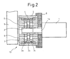
- the servo motor 1 is attached to the first member 8, and the output shaft 1a of the servo motor 1 is directly connected to the input shaft 2 of the speed reducer, the entire body of which is shown by the reference numeral 10.
- the input shaft 2 of the speed reducer is a crank shaft composing a cam, and the three external gears 3a, 3b, 3c are meshed with the respective cam faces.
- the case 5 of the speed reducer 10 is attached to the first member 8. Inside the case 5, the internal gear 4 meshed with each external gear 3a, 3b, 3c is provided. Further, multiple pin members 6 are engaged with the external gears 3a, 3b, 3c, and the pin member 6 is connected to the output shaft 7 of the speed reducer 10.
- This output shaft 7 is attached to the second member 9 and pivotally supported by the case 5 of the speed reducer 10 while the output shaft 7 and the input shaft 2 are aligned on the same axis.
- the external gears 3a, 3b, 3c are rotated by (n 2 - n 1 )/n 2 rotation, during the one revolution of the external gears 3a, 3b, 3c.
- This rotating motion is taken out by a plurality of pin members 6, which are engaged to the external gears 3a, 3b, 3c, to transmit it to the output shaft 7 of the speed reducer 10.
- the second member 9 is relatively pivoted with respect to the first member 8.
- the speed reduction ratio (the rotational speed ratio) is (n 2 - n 1 )/n 2 .
- the speed reducer 10 to connect the adjoining links conducts a speed reduction of one-stage of the eccentric rotation type planetary differential reduction gear mechanism.
- the structure of the speed reducer 10 is very simple.
- the servo motor is directly connected to the input shaft of the speed reducer, the structure of the joint mechanism can be advantageously simplified.
Landscapes
- Engineering & Computer Science (AREA)
- Robotics (AREA)
- Mechanical Engineering (AREA)
- Manipulator (AREA)
Abstract
A joint structure is employed for an articulated type robot in which a speed reducer of one-stage speed reducing structure and a servo motor are directly connected to each other for the joint of the rotary base (B1) and and the lower arm (A1) and for the joint of the lower arm (A1) and the upper arm (A2). The input shaft (2) of the speed reducer (10) directly connected to the output shaft of the servo motor (1) attached to the first member (8) (B1/A2) is a crank shaft composing a cam, and the external gears (3a,3b,3c) are meshed with the cam surfaces. When the servo motor (1) is driven and the input shaft (2) is rotated, the external gears (3a,3b,3c) are eccentrically revolved and rotated while the external gears (3a,3b,3c) are meshed with the internal gear (4) provided inside the case (5) of the speed reducer (10). The rotation is taken out by a plurality of pin members (6) engaged to the external gears (3a,3b,3c) and transmitted to the output shaft (7) of the speed reducer (10). Therefore, the second member (9) (A1) is relatively pivoted with respect to the first member (8). Due to the foregoing, the robot structure in which a plurality of joint devices for connecting the adjoining links via the speed reducer are connected in series to each other can be simplified.
Description
The present invention relates to an industrial
robot. More particularly, the present invention relates
to an industrial robot having an arm structure using a
rotary joint mechanism to rotate adjoining links, by a
servo motor, via a speed reducing mechanism of a speed
reducer.
In general, a joint structure of an industrial
robot is provided with a speed reducer. As the reduction
ratio of the speed reducer is high, a speed reducer, such
as Cyclo Speed Reducer (registered trade mark) or RV
Speed Reducer (registered trade mark), in which an
eccentric rotation type planetary differential reduction
gear mechanism is employed, is widely used. For example,
the mechanism eccentric rotation type planetary
differential reduction gear speed reducer referred to as
a Cyclo Speed Reducer (registered trade mark) includes:
an eccentric body shaft which is also the input shaft of
the speed reducer; an external gear attached to the
eccentric body shaft via a bearing to allow eccentric
rotation; an internal gear inner meshed with the external
gear; a roller hole formed in the external gear; a pin
loosely fit in the roller hole; and an output shaft fixed
to the pin in such a manner that only the rotation
component of the external gear is transmitted via the
pin. The above joint structure is also applied to an
articulated type robot. In this articulated type robot,
multiple joint devices (bodies in which links are
connected with each other), in which arms are connected
with each other via a speed reducer, are connected in
series with each other, so that a simple structure is
realized.
However, if the joint structure, in which the
eccentric rotation type planetary differential reduction
gear speed reducer is used, is applied to a robot,
especially to the aforementioned articulated type robot,
vibration is caused by the eccentric motion of the
planetary gear. Accordingly, the operation of the robot
tends to include the vibration. In order to solve the
above problems, the following method is commonly used.
It is conventional that a gear speed reducing section is
provided in the primary stage of the eccentric rotation
type planetary differential reduction gear speed reducer,
so that the vibration frequency of the speed reducer
which causes resonance vibration between the speed
reducer and the robot, can be excluded from the normal
controlling speed range of the motor.
For example, Japanese Examined Patent
Publication No. 8-22516 discloses an example in which
this type of speed reducer is used. The speed reducer
disclosed in Japanese Examined Patent Publication No. 8-22516
is composed of a primary stage speed reducer of a
parallel shaft type gear device and a secondary stage
speed reducer. The secondary stage speed reducer
includes: an internal gear fixed to a case or the like;
an external gear meshed with the internal gear; and a
crank shaft as a cam shaft meshed with the external gear
to eccentrically rotate the external gear. In this
structure, the generation of vibration is prevented by
setting a reduction ratio of the primary stage speed
reducer in such a manner that vibration cannot be
generated by the eccentric rotation motion of the
secondary stage speed reducer in the normal controlling
speed range of the motor.
However, the above speed reducer has a two-stage
speed reducing structure composed of a primary
speed reducing section and a secondary speed reducing
section. Therefore, the structure of the speed reducer
becomes complicated, which results to increased
manufacturing costs. Especially, in the case of the
articulated type robot, multiple joints using this two-stage
speed reducing type speed reducer are connected in
series to each other. Therefore, the manufacturing cost
of the speed reducer occupies a large portion of the
manufacturing cost of the entire robot. Accordingly, it
is difficult for the manufacturing cost of the entire
robot to be reduced because the manufacturing cost of the
speed reducer is high.
The object of this invention is to easily
reduce the manufacturing cost of the entire robot by
simplifying "the structure in which multiple joints using
a speed reducer are connected in series to each other" in
the industrial robot.
The present invention provides an inexpensive
articulated type industrial robot of a simple structure
in which multiple joint devices are connected in series
to each other, wherein a speed reducer having one-stage
speed reducing structure, the speed reducing mechanism of
which is composed of only a planetary gear speed reducing
mechanism, is employed in the joint device, arms are
pivotably connected to each other via the speed reducer
and an input shaft of the speed reducer is directly
connected to a servo motor.
In order to solve the above problems, the present
invention provides an industrial robot having an arm
structure, in which, when adjoining links are relatively
pivotably connected to each other via a speed reducer
driven by a servo motor, a one-stage speed reducing type
speed reducer having only an eccentric rotation type
planetary differential reduction gear mechanism as a
speed reducing mechanism is employed, the rotary joint
mechanisms, the number of which is greater than or equal
to N (N is a positive integer greater than or equal to
2.), are arranged in series so as to connect the links,
the number of which is N + 1.
More specifically, the present invention provides an
industrial robot comprising an arm structure, the arm
structure including a speed reducer for relatively
pivotably connecting adjoining links to each other and
also including a servo motor for driving the speed
reducer so as to pivot the adjoining links, wherein the
links, the number of which is N + 1, are connected in
series to each other by the rotary joint mechanisms, the
number of which is N (N ≥ 2), a speed reduction mechanism
of the speed reducer is composed of only a one-stage
speed reduction type eccentric rotation type planetary
differential reduction gear mechanism, a casing of the
speed reducer is fixed to one of the adjoining links, the
other of the links is fixed to an output shaft of the
speed reducer, an output shaft of the servo motor and a
rotary shaft of the rotary joint mechanism provided with
the servo motor are aligned on the same axis, and an
output shaft of the servo motor is connected to an input
shaft of the speed reducer so as to transmit a drive
force.
In this connection, it can be considered that
vibration tends to occur in the case where the eccentric
rotation type planetary differential reduction gear speed
reduction mechanism of a one-stage speed reduction type
is employed. However, when conventional methods for
suppressing the generation of vibration are appropriately
used being combined with each other, such vibration can
be suppressed. Such methods for suppressing the
generation of vibration are described in the following
items (1) to (3).
According to the present invention, it is possible
to simplify the structure in which multiple joint devices
(bodies in which links are combined with each other) of
an industrial robot, the arms of which are connected to
each other via a speed reducer, are connected in series
to each other. According to the present invention, for
example, it becomes possible to provide an articulated
type robots at a low manufacturing cost.
These and other objects, features and advantages of
the present invention will be more apparent in light of
the detailed description of exemplary embodiments thereof
as illustrated by the drawings.
In the drawings:
Referring to Figs 1 and 2, an embodiment of the
present invention will be explained below. First of all,
referring to Fig. 1, the appearance of a robot to which
the present invention is applied is exemplarily shown in
the perspective view. As shown in this drawing, the
robot is an articulated type robot of six axes including:
a base B0; a rotary base B1 operated around axis J1; a
lower arm A1 operated around axis J2; an upper arm A2
operated around axis J3; and a wrist unit H operated
around the three axes (J4 to J6) of the wrist unit so
that the wrist unit H can be moved with a three-degrees-of-freedom.
In this embodiment, the joint structure of
the present invention is applied to the link combinations
of the robot rotary base B1, the lower arm A1 and the
upper arm A2.
Needless to say, "the two adjoining links" included
in these three links are "the rotary base B1 and the
lower arm A1" and "the lower arm A1 and the upper arm
A2", and the joint for relatively rotating the rotary
base B1 and the lower arm A1 is axis J2, and the joint
for relatively rotating the lower arm A1 and the upper
arm A2 is axis J3. The joint structure of the respective
axis J2 and the axis J3 is composed in such a manner that
the adjoining links (the rotary base B1 and the lower arm
A1, or the lower arm A1 and the upper arm A2) are
connected to each other via the speed reducer and that
the servo motor is directly connected to the speed
reducer. The axis J2 and the axis J3 are connected in
series to each other via the lower arm A1. That is, one
joint device explained below is used in each of the axis
J2 and the axis J3. The two joints can be connected in
series to each other, while the second link (the lower
arm A1 in this case) in the three links is interposed.
Referring to Fig. 2 showing the sectional structure,
the joint device used for the axis J2 and the axis J3
will be explained as follows. In this connection, in the
related explanations of Fig. 2, "the first member" and
"the second member" have the following meanings in the
joint device used for the axis J2.
The first member is a member constituting at least
one portion of the rotary base B1.
The second member is a member constituting at least
one portion of the lower arm A1.
In the joint device used for the axis J3, "the first
member" and "the second member" have the following
meanings.
The first member is a member constituting at least
one portion of the upper arm A2.
The second member is a member constituting at least
one portion of the lower arm A1.
In the joint device used for the axis J2, the servo
motor is a drive source for driving the axis J2. In the
joint device used for the axis J3, the servo motor is a
drive source for driving the axis J3.
As drawn in Fig. 2, the servo motor 1 is attached to
the first member 8, and the output shaft 1a of the servo
motor 1 is directly connected to the input shaft 2 of the
speed reducer, the entire body of which is shown by the
reference numeral 10. The input shaft 2 of the speed
reducer is a crank shaft composing a cam, and the three
external gears 3a, 3b, 3c are meshed with the respective
cam faces. The case 5 of the speed reducer 10 is
attached to the first member 8. Inside the case 5, the
internal gear 4 meshed with each external gear 3a, 3b, 3c
is provided. Further, multiple pin members 6 are engaged
with the external gears 3a, 3b, 3c, and the pin member 6
is connected to the output shaft 7 of the speed reducer
10. This output shaft 7 is attached to the second member
9 and pivotally supported by the case 5 of the speed
reducer 10 while the output shaft 7 and the input shaft 2
are aligned on the same axis.
In the joint device having the structure described
above, when the servo motor 1 is driven, the input shaft
2 of the speed reducer 10 directly connected to the
output shaft 1a of the servo motor 1 is rotated. Then,
the external gears 3a, 3b, 3c meshed with the crank shaft
portion (cam) of the input shaft 2 are eccentrically
rotated. While the external gears 3a, 3b, 3c are meshed
with the internal gear 4 provided inside the case 5 of
the speed reducer 10, the external gears 3a, 3b, 3c
conduct a revolving motion and a rotating motion at the
same time. Where the number of teeth of the external
gears 3a, 3b, 3c is n1 and the number of teeth of the
internal gear 4 is n2. the external gears 3a, 3b, 3c are
rotated by (n2 - n1)/n2 rotation, during the one
revolution of the external gears 3a, 3b, 3c. This
rotating motion is taken out by a plurality of pin
members 6, which are engaged to the external gears 3a,
3b, 3c, to transmit it to the output shaft 7 of the speed
reducer 10. As a result, the second member 9 is
relatively pivoted with respect to the first member 8.
In this case, the speed reduction ratio (the rotational
speed ratio) is (n2 - n1)/n2.
As described above, the speed reducer 10 to connect
the adjoining links conducts a speed reduction of one-stage
of the eccentric rotation type planetary
differential reduction gear mechanism. Compared with the
speed reducer described above in which the two-stage
speed reducing structure is employed, the structure of
the speed reducer 10 is very simple. Further, as the
servo motor is directly connected to the input shaft of
the speed reducer, the structure of the joint mechanism
can be advantageously simplified. When multiple devices
described above are continuously connected in series to
each other, it is possible to achieve a robot, the
degree-of-freedom of which is high, having a structure
which is simple. In the above embodiment, explanations
are made into a case of N = 2 in which three links are
connected by two joint devices. However, as necessary,
it is possible to apply the present invention to a case
of N = 3 or more.
Although the invention has been shown and described
with exemplary embodiments thereof, it should be
understood by those skilled in the art that the foregoing
and various other changes, omissions and additions may be
made therein and thereto without departing from the
spirit and the scope of the invention.
Claims (1)
- An industrial robot including an arm structure in which links, the number of which is N + 1, are connected in series to each other by rotary joint mechanisms, the number of which is N (N is a positive integer greater than or equal to 2.), characterized in that
the rotary joint mechanisms, the number of which is N, include: a speed reducer (10) for relatively pivotally connecting the adjoining links (B1, A1; A1, A2) to each other; and a servo motor (1) for driving the speed reducer (10) so as to rotate the adjoining links,
a speed reduction mechanism of the speed reducer (10) is composed of only a one-stage speed reduction type eccentric rotation type planetary differential reduction gear mechanism (3a, 3b, 3c, 4),
a casing (5) of the speed reducer (10) is fixed to one of the adjoining links (B1, A1; A1, A2), the other of the adjoining links (B1, A1, ; A1, A2) is fixed to an output shaft (7) of the speed reducer (10),
an output shaft (1a) of the servo motor (1) and a rotary shaft of the rotary joint mechanism provided with the servo motor (1) are arranged on the same straight line, and
the output shaft (1a) of the servo motor (1) is connected to an input shaft (2) of the speed reducer (10) so as to transmit a drive force.
Applications Claiming Priority (2)
| Application Number | Priority Date | Filing Date | Title |
|---|---|---|---|
| JP2004074573 | 2004-03-16 | ||
| JP2004074573A JP2005262340A (en) | 2004-03-16 | 2004-03-16 | Industrial robot |
Publications (1)
| Publication Number | Publication Date |
|---|---|
| EP1577062A1 true EP1577062A1 (en) | 2005-09-21 |
Family
ID=34836511
Family Applications (1)
| Application Number | Title | Priority Date | Filing Date |
|---|---|---|---|
| EP05005393A Withdrawn EP1577062A1 (en) | 2004-03-16 | 2005-03-11 | Industrial robot with speed reducer in rotary joints |
Country Status (4)
| Country | Link |
|---|---|
| US (1) | US20050204850A1 (en) |
| EP (1) | EP1577062A1 (en) |
| JP (1) | JP2005262340A (en) |
| CN (1) | CN1669746A (en) |
Cited By (3)
| Publication number | Priority date | Publication date | Assignee | Title |
|---|---|---|---|---|
| CN102705453A (en) * | 2012-06-13 | 2012-10-03 | 张宽友 | Internal-vibration multi-crankshaft small-tooth difference speed reducer |
| CN111958582A (en) * | 2020-09-11 | 2020-11-20 | 东莞市尔必地机器人有限公司 | Seven-axis robot |
| CN112847325A (en) * | 2021-01-11 | 2021-05-28 | 国工信(沧州)机器人有限公司 | X-shaped large arm of industrial robot for laser cutting |
Families Citing this family (59)
| Publication number | Priority date | Publication date | Assignee | Title |
|---|---|---|---|---|
| WO2006037059A2 (en) * | 2004-09-27 | 2006-04-06 | The Johns Hopkins Universtiy | Point-of-care mass spectrometer system |
| WO2007046754A1 (en) * | 2005-10-21 | 2007-04-26 | Abb Ab | An arm part of an industrial robot as well as an indus- trial robot provided therewith |
| USD545334S1 (en) * | 2006-05-31 | 2007-06-26 | Kraft Telebobotics, Inc. | Robotic master controller |
| US10174810B2 (en) | 2006-06-21 | 2019-01-08 | Northeastern University | Curved bearing contact system |
| US8016893B2 (en) * | 2006-06-21 | 2011-09-13 | The United States Of America As Represented By The Administrator Of The National Aeronautics And Space Administration | Gear bearing drive |
| USD569886S1 (en) * | 2006-12-27 | 2008-05-27 | Abb Ab | Robot arm |
| US8176808B2 (en) * | 2007-09-13 | 2012-05-15 | Foster-Miller, Inc. | Robot arm assembly |
| US8201649B2 (en) * | 2007-12-14 | 2012-06-19 | Foster-Miller, Inc. | Modular mobile robot |
| JP4603604B2 (en) * | 2008-08-01 | 2010-12-22 | ファナック株式会社 | Robot system that attaches and detaches workpieces to machine tools by robot |
| US8414043B2 (en) * | 2008-10-21 | 2013-04-09 | Foster-Miller, Inc. | End effector for mobile remotely controlled robot |
| US20100101356A1 (en) * | 2008-10-24 | 2010-04-29 | Albin Scott R | Remotely controlled mobile robot in-line robot arm and end effector mechanism |
| US8322249B2 (en) | 2008-12-18 | 2012-12-04 | Foster-Miller, Inc. | Robot arm assembly |
| US8141924B2 (en) | 2008-12-29 | 2012-03-27 | Foster-Miller, Inc. | Gripper system |
| JP5406644B2 (en) * | 2009-09-14 | 2014-02-05 | ナブテスコ株式会社 | Swivel device |
| CN102059695A (en) * | 2009-11-18 | 2011-05-18 | 鸿富锦精密工业(深圳)有限公司 | Robot arm component, manufacturing method thereof and robot with arm component |
| USD636803S1 (en) * | 2010-03-19 | 2011-04-26 | Kobe Steel, Ltd. | Industrial robot |
| USD636419S1 (en) * | 2010-03-19 | 2011-04-19 | Kobe Steel, Ltd. | Industrial robot |
| USD636004S1 (en) * | 2010-03-19 | 2011-04-12 | Kobe Steel, Ltd. | Industrial robot |
| JP5457922B2 (en) * | 2010-04-14 | 2014-04-02 | 株式会社ダイヘン | Industrial robot |
| CN102233585A (en) * | 2010-04-29 | 2011-11-09 | 鸿富锦精密工业(深圳)有限公司 | Arm member of robot |
| USD638043S1 (en) * | 2010-05-24 | 2011-05-17 | Denso Corporation | Industrial robot |
| USD638044S1 (en) * | 2010-05-24 | 2011-05-17 | Denso Corporation | Industrial robot |
| CN102338197B (en) * | 2010-07-20 | 2014-01-15 | 鸿富锦精密工业(深圳)有限公司 | Gear transmission device and mechanical arm with the gear transmission device |
| CN102431039B (en) * | 2010-09-29 | 2014-12-10 | 鸿富锦精密工业(深圳)有限公司 | Mechanical arm |
| USD638455S1 (en) * | 2010-11-23 | 2011-05-24 | Hon Hai Precision Industry Co., Ltd. | Robot |
| USD651627S1 (en) * | 2011-08-15 | 2012-01-03 | Hon Hai Precision Industry Co., Ltd. | Robot |
| USD650820S1 (en) * | 2011-08-19 | 2011-12-20 | Hon Hai Precision Industry Co., Ltd. | Robot |
| JP5408212B2 (en) * | 2011-09-07 | 2014-02-05 | 株式会社安川電機 | Working robot and processing equipment |
| WO2013054405A1 (en) * | 2011-10-12 | 2013-04-18 | 株式会社安川電機 | Multi-jointed robot |
| USD670319S1 (en) * | 2012-01-11 | 2012-11-06 | Hon Hai Precision Industry Co., Ltd. | Robot |
| USD677294S1 (en) * | 2012-09-14 | 2013-03-05 | Hon Hai Precision Industry Co., Ltd. | Robot |
| JP2014077453A (en) * | 2012-10-09 | 2014-05-01 | Nabtesco Corp | Eccentric oscillation type gear device |
| JP5617900B2 (en) * | 2012-11-19 | 2014-11-05 | 株式会社安川電機 | robot |
| USD690753S1 (en) * | 2012-11-26 | 2013-10-01 | Hon Hai Precision Industry Co., Ltd. | Robot |
| JP5418704B1 (en) * | 2013-01-17 | 2014-02-19 | 株式会社安川電機 | robot |
| USD707277S1 (en) * | 2013-06-14 | 2014-06-17 | Abb Technology Ltd. | Robot |
| JP5884785B2 (en) * | 2013-07-30 | 2016-03-15 | 株式会社安川電機 | robot |
| CN103612265A (en) * | 2013-11-26 | 2014-03-05 | 苏州晓炎自动化设备有限公司 | Robot elbow joint front-end rotating mechanism |
| JP2015196237A (en) * | 2014-04-03 | 2015-11-09 | ナブテスコ株式会社 | Humanoid robot joint mechanism |
| US9718187B2 (en) * | 2014-06-11 | 2017-08-01 | Canon Kabushiki Kaisha | Robot controlling method, robot apparatus, program, recording medium, and method for manufacturing assembly component |
| CN104400014B (en) * | 2014-11-05 | 2017-01-11 | 苏州道众机械制造有限公司 | Mechanical arm rotating mechanism |
| CN104476560B (en) * | 2014-12-15 | 2016-09-21 | 宏光空降装备有限公司 | The revolute joint mechanism of boosting manipulator |
| CA165885S (en) * | 2015-08-21 | 2016-07-08 | Schuler Ag | Robot |
| TWD176129S (en) * | 2015-09-24 | 2016-06-01 | 上銀科技股份有限公司 | Robotic arm |
| JP1558048S (en) * | 2015-10-30 | 2016-09-05 | ||
| JP6681201B2 (en) * | 2016-01-22 | 2020-04-15 | ナブテスコ株式会社 | Steering device |
| CN106801722B (en) * | 2017-03-14 | 2019-02-15 | 洁誉科技(上海)股份有限公司 | A kind of novel robot speed reducer |
| CN108188938A (en) * | 2017-12-12 | 2018-06-22 | 清研同创机器人(天津)有限公司 | A kind of five novel axis sand blasting machine people |
| CN108468776A (en) * | 2018-02-14 | 2018-08-31 | 于杰 | deceleration device |
| JP6708684B2 (en) * | 2018-03-20 | 2020-06-10 | ファナック株式会社 | Structure of joint part of robot equipped with drive motor and speed reducer |
| CN108662089B (en) * | 2018-06-26 | 2024-06-25 | 深圳市零差云控科技有限公司 | Servo reducer and robot reduction joint using the servo reducer |
| CN110185748B (en) * | 2019-06-05 | 2022-02-22 | 南通振康机械有限公司 | Integrated robot joint structure |
| CN114072259B (en) * | 2019-07-24 | 2025-04-18 | Abb瑞士股份有限公司 | Robot and assembly method thereof |
| JP2021158751A (en) | 2020-03-26 | 2021-10-07 | セイコーエプソン株式会社 | Robots and robot systems |
| JP7171669B2 (en) * | 2020-10-14 | 2022-11-15 | 川崎重工業株式会社 | Surgery support system, patient-side device, and control method for surgery support system |
| CN113119093A (en) * | 2021-04-10 | 2021-07-16 | 新乡市银星机械设备有限公司 | Automatic welding and cutting robot |
| CN115446812A (en) * | 2022-08-11 | 2022-12-09 | 深圳市越疆科技有限公司 | Base drive components, lightweight industrial desktop manipulator arms, and robots |
| CN117103317A (en) * | 2023-05-23 | 2023-11-24 | 江苏理工学院 | An automatic loading and unloading manipulator for lathes |
| CN117168802B (en) * | 2023-08-14 | 2024-06-18 | 苏州长木传动科技有限公司 | A method for detecting the performance and life of a harmonic reducer |
Citations (5)
| Publication number | Priority date | Publication date | Assignee | Title |
|---|---|---|---|---|
| JPS59106744A (en) * | 1982-12-07 | 1984-06-20 | Sumitomo Heavy Ind Ltd | Method and device for installing eccentric body in planetary gear mechanism |
| US4690010A (en) * | 1985-01-18 | 1987-09-01 | Teijin Seiki Company Limited | Robot arm drive apparatus of industrial robot |
| JPH03209038A (en) * | 1990-01-09 | 1991-09-12 | Harmonic Drive Syst Ind Co Ltd | Planetary gearing device |
| EP0710782A1 (en) * | 1994-06-01 | 1996-05-08 | Fanuc Ltd. | Planetary gear type speed reducer |
| US20030134708A1 (en) * | 2002-01-11 | 2003-07-17 | Otto Regner | Cyclo torque multipliers |
Family Cites Families (8)
| Publication number | Priority date | Publication date | Assignee | Title |
|---|---|---|---|---|
| US1455360A (en) * | 1921-10-10 | 1923-05-15 | William E Sharkey | Reduction gearing |
| US1578965A (en) * | 1924-12-03 | 1926-03-30 | Roberts & Schaefer Company | Automatic reversible hoist |
| US3160032A (en) * | 1961-05-25 | 1964-12-08 | Black Tool Inc | Epicyclic speed changing device and gear form therefor |
| JPS597593A (en) * | 1982-07-02 | 1984-01-14 | 三菱電機株式会社 | Joint device for robot |
| JPS6174935A (en) * | 1984-09-20 | 1986-04-17 | Yasuo Goto | Speed change gear |
| US4685861A (en) * | 1984-10-30 | 1987-08-11 | Michael Madock | Continuous shaft-driven industrial robot |
| FR2684154A1 (en) * | 1991-11-21 | 1993-05-28 | Staubli Sa Ets | CYCLOUIDAL SPEED REDUCER FOR ROBOTS AND OTHER INDUSTRIAL MANIPULATORS. |
| EP0551050B1 (en) * | 1992-01-10 | 1996-06-26 | AGINFOR AG für industrielle Forschung | Eccentric gearing |
-
2004
- 2004-03-16 JP JP2004074573A patent/JP2005262340A/en active Pending
-
2005
- 2005-03-11 EP EP05005393A patent/EP1577062A1/en not_active Withdrawn
- 2005-03-15 US US11/079,679 patent/US20050204850A1/en not_active Abandoned
- 2005-03-16 CN CNA2005100555491A patent/CN1669746A/en active Pending
Patent Citations (5)
| Publication number | Priority date | Publication date | Assignee | Title |
|---|---|---|---|---|
| JPS59106744A (en) * | 1982-12-07 | 1984-06-20 | Sumitomo Heavy Ind Ltd | Method and device for installing eccentric body in planetary gear mechanism |
| US4690010A (en) * | 1985-01-18 | 1987-09-01 | Teijin Seiki Company Limited | Robot arm drive apparatus of industrial robot |
| JPH03209038A (en) * | 1990-01-09 | 1991-09-12 | Harmonic Drive Syst Ind Co Ltd | Planetary gearing device |
| EP0710782A1 (en) * | 1994-06-01 | 1996-05-08 | Fanuc Ltd. | Planetary gear type speed reducer |
| US20030134708A1 (en) * | 2002-01-11 | 2003-07-17 | Otto Regner | Cyclo torque multipliers |
Non-Patent Citations (2)
| Title |
|---|
| PATENT ABSTRACTS OF JAPAN vol. 008, no. 224 (M - 331) 13 October 1984 (1984-10-13) * |
| PATENT ABSTRACTS OF JAPAN vol. 015, no. 485 (M - 1188) 9 December 1991 (1991-12-09) * |
Cited By (3)
| Publication number | Priority date | Publication date | Assignee | Title |
|---|---|---|---|---|
| CN102705453A (en) * | 2012-06-13 | 2012-10-03 | 张宽友 | Internal-vibration multi-crankshaft small-tooth difference speed reducer |
| CN111958582A (en) * | 2020-09-11 | 2020-11-20 | 东莞市尔必地机器人有限公司 | Seven-axis robot |
| CN112847325A (en) * | 2021-01-11 | 2021-05-28 | 国工信(沧州)机器人有限公司 | X-shaped large arm of industrial robot for laser cutting |
Also Published As
| Publication number | Publication date |
|---|---|
| US20050204850A1 (en) | 2005-09-22 |
| CN1669746A (en) | 2005-09-21 |
| JP2005262340A (en) | 2005-09-29 |
Similar Documents
| Publication | Publication Date | Title |
|---|---|---|
| US20050204850A1 (en) | Industrial robot | |
| EP3715061B1 (en) | Robot wrist structure and robot | |
| KR100749349B1 (en) | Power transmission apparatus for driving the wrist of robot and power transmission apparatus | |
| US4807486A (en) | Three-axes wrist mechanism | |
| EP0249232B1 (en) | Wrist device of robot | |
| US8162789B2 (en) | Reduction gear box | |
| US11938624B2 (en) | Parallel kinematic robot | |
| CN110666833A (en) | Rope-driven seven-degree-of-freedom humanoid mechanical arm based on parallel mechanism | |
| WO2009098945A1 (en) | Gear power transmission device | |
| JP5270449B2 (en) | Robot joint structure and robot including the same | |
| JP6629106B2 (en) | Robot joint drive structure | |
| JP2563266Y2 (en) | Eccentric differential reducer | |
| JPS63163063A (en) | Two-degree of freedom driving mechanism performing straight advancing motion and rotary motion | |
| US5050450A (en) | Wrist mechanism for industrial robot or the like | |
| KR20060095266A (en) | Robot module | |
| JP2001113488A (en) | Industrial robot | |
| KR20230000962A (en) | Speed reducer and rotating device | |
| JPH068183A (en) | Articulated robot | |
| CN101642910B (en) | Filtering driving device and intelligent robot integrated system | |
| JPH11198086A (en) | Reducer for joint drive of industrial robot | |
| CN111283721B (en) | Hinge type robot joint | |
| JPH0248193A (en) | Wrist drive mechanism of industrial robot | |
| CN115338876B (en) | Six-degree-of-freedom joint robot | |
| CN112549071A (en) | Mechanical arm and robot | |
| JPH05253882A (en) | Robot having wrist of three degrees of freedom |
Legal Events
| Date | Code | Title | Description |
|---|---|---|---|
| PUAI | Public reference made under article 153(3) epc to a published international application that has entered the european phase |
Free format text: ORIGINAL CODE: 0009012 |
|
| 17P | Request for examination filed |
Effective date: 20050714 |
|
| AK | Designated contracting states |
Kind code of ref document: A1 Designated state(s): AT BE BG CH CY CZ DE DK EE ES FI FR GB GR HU IE IS IT LI LT LU MC NL PL PT RO SE SI SK TR |
|
| AX | Request for extension of the european patent |
Extension state: AL BA HR LV MK YU |
|
| AKX | Designation fees paid |
Designated state(s): DE |
|
| STAA | Information on the status of an ep patent application or granted ep patent |
Free format text: STATUS: THE APPLICATION IS DEEMED TO BE WITHDRAWN |
|
| 18D | Application deemed to be withdrawn |
Effective date: 20061031 |