EP1577039A1 - Braking mechanism for a jig saw - Google Patents
Braking mechanism for a jig saw Download PDFInfo
- Publication number
- EP1577039A1 EP1577039A1 EP05251469A EP05251469A EP1577039A1 EP 1577039 A1 EP1577039 A1 EP 1577039A1 EP 05251469 A EP05251469 A EP 05251469A EP 05251469 A EP05251469 A EP 05251469A EP 1577039 A1 EP1577039 A1 EP 1577039A1
- Authority
- EP
- European Patent Office
- Prior art keywords
- inner wheel
- braking
- braking mechanism
- rack
- retaining
- Prior art date
- Legal status (The legal status is an assumption and is not a legal conclusion. Google has not performed a legal analysis and makes no representation as to the accuracy of the status listed.)
- Withdrawn
Links
- 230000005540 biological transmission Effects 0.000 claims abstract description 37
- 238000005096 rolling process Methods 0.000 claims abstract description 19
- 230000008878 coupling Effects 0.000 claims description 8
- 238000010168 coupling process Methods 0.000 claims description 8
- 238000005859 coupling reaction Methods 0.000 claims description 8
- 239000003999 initiator Substances 0.000 description 7
- 230000009194 climbing Effects 0.000 description 1
- 238000004519 manufacturing process Methods 0.000 description 1
- 230000000717 retained effect Effects 0.000 description 1
Images


Classifications
-
- F—MECHANICAL ENGINEERING; LIGHTING; HEATING; WEAPONS; BLASTING
- F16—ENGINEERING ELEMENTS AND UNITS; GENERAL MEASURES FOR PRODUCING AND MAINTAINING EFFECTIVE FUNCTIONING OF MACHINES OR INSTALLATIONS; THERMAL INSULATION IN GENERAL
- F16D—COUPLINGS FOR TRANSMITTING ROTATION; CLUTCHES; BRAKES
- F16D41/00—Freewheels or freewheel clutches
- F16D41/06—Freewheels or freewheel clutches with intermediate wedging coupling members between an inner and an outer surface
- F16D41/064—Freewheels or freewheel clutches with intermediate wedging coupling members between an inner and an outer surface the intermediate members wedging by rolling and having a circular cross-section, e.g. balls
- F16D41/066—Freewheels or freewheel clutches with intermediate wedging coupling members between an inner and an outer surface the intermediate members wedging by rolling and having a circular cross-section, e.g. balls all members having the same size and only one of the two surfaces being cylindrical
- F16D41/067—Freewheels or freewheel clutches with intermediate wedging coupling members between an inner and an outer surface the intermediate members wedging by rolling and having a circular cross-section, e.g. balls all members having the same size and only one of the two surfaces being cylindrical and the members being distributed by a separate cage encircling the axis of rotation
-
- B—PERFORMING OPERATIONS; TRANSPORTING
- B23—MACHINE TOOLS; METAL-WORKING NOT OTHERWISE PROVIDED FOR
- B23D—PLANING; SLOTTING; SHEARING; BROACHING; SAWING; FILING; SCRAPING; LIKE OPERATIONS FOR WORKING METAL BY REMOVING MATERIAL, NOT OTHERWISE PROVIDED FOR
- B23D51/00—Sawing machines or sawing devices working with straight blades, characterised only by constructional features of particular parts; Carrying or attaching means for tools, covered by this subclass, which are connected to a carrier at both ends
- B23D51/16—Sawing machines or sawing devices working with straight blades, characterised only by constructional features of particular parts; Carrying or attaching means for tools, covered by this subclass, which are connected to a carrier at both ends of drives or feed mechanisms for straight tools, e.g. saw blades, or bows
- B23D51/166—Devices for arresting movement of the saw blades
-
- B—PERFORMING OPERATIONS; TRANSPORTING
- B25—HAND TOOLS; PORTABLE POWER-DRIVEN TOOLS; MANIPULATORS
- B25F—COMBINATION OR MULTI-PURPOSE TOOLS NOT OTHERWISE PROVIDED FOR; DETAILS OR COMPONENTS OF PORTABLE POWER-DRIVEN TOOLS NOT PARTICULARLY RELATED TO THE OPERATIONS PERFORMED AND NOT OTHERWISE PROVIDED FOR
- B25F5/00—Details or components of portable power-driven tools not particularly related to the operations performed and not otherwise provided for
- B25F5/001—Gearings, speed selectors, clutches or the like specially adapted for rotary tools
-
- F—MECHANICAL ENGINEERING; LIGHTING; HEATING; WEAPONS; BLASTING
- F16—ENGINEERING ELEMENTS AND UNITS; GENERAL MEASURES FOR PRODUCING AND MAINTAINING EFFECTIVE FUNCTIONING OF MACHINES OR INSTALLATIONS; THERMAL INSULATION IN GENERAL
- F16D—COUPLINGS FOR TRANSMITTING ROTATION; CLUTCHES; BRAKES
- F16D63/00—Brakes not otherwise provided for; Brakes combining more than one of the types of groups F16D49/00 - F16D61/00
- F16D63/006—Positive locking brakes
-
- F—MECHANICAL ENGINEERING; LIGHTING; HEATING; WEAPONS; BLASTING
- F16—ENGINEERING ELEMENTS AND UNITS; GENERAL MEASURES FOR PRODUCING AND MAINTAINING EFFECTIVE FUNCTIONING OF MACHINES OR INSTALLATIONS; THERMAL INSULATION IN GENERAL
- F16D—COUPLINGS FOR TRANSMITTING ROTATION; CLUTCHES; BRAKES
- F16D65/00—Parts or details
- F16D65/14—Actuating mechanisms for brakes; Means for initiating operation at a predetermined position
Definitions
- the present invention relates to a braking mechanism for a power tool.
- a power tool generally exploits a rotary motor to drive a working mechanism via a transmission mechanism.
- the working mechanism should stop instantly for safety reasons.
- the power tool often incorporates a braking mechanism to assist in decelerating the working mechanism.
- the braking mechanism is also arranged to halt the rotary motor and the transmission mechanism, the size of the rotary motor may induce an internal force which damages the transmission mechanism and makes a loud noise.
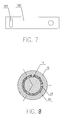
- Figure 8 relates to the disclosure of DE-4418102A in which a braking mechanism comprises an initiator device 12, a passive device 14, a retaining device 26 and a roller 24.
- the passive device 14 is a cylinder defining a uniform face to cooperate with the roller 24.
- the initiator device 12 drives the retaining device 26 to move in the same direction.
- the roller 24 interferes with the passive device 14 and the initiator device 12, the initiator device 12, the passive device 14 and the retaining device 26 move together.
- the retaining device 26 is retained, the roller 24 is displaced and the passive device 14 moves till the roller 24 interferes with the initiator device 12 and the passive device 14 again, whilst the initiator device 12 rolls on.
- This braking mechanism has two disadvantages.
- the uniform face of the passive device 12 is a climbing face and little free movement of the roller 24 is allowed so that if the precision of manufacture is low, brake failure may occur.
- the initiator device 12 drives the passive device 14 and brakes through the retaining force of the roller 24 so that the roller 24 may easily deform.
- the present invention is based on the recognition that a braking mechanism which is adapted to stop the reciprocation of a reciprocative power tool without intervening directly in the rotation of the rotary motor will prolong the lifetime of the power tool.
- the present invention provides a braking mechanism for a reciprocative power tool comprising:
- the present invention achieves a stable braking action with low noise output.
- the braking mechanism has convenient longevity, whilst being manufactured easily.
- the inner wheel decelerates until the stopper collides with the projection.
- the rolling device is a cylindrical roller or ball bearing.
- the rolling device eg cylindrical roller
- the rolling device is axially disposed in the notch.
- the transmission rack is a gear rim defining an axis hole along the axial direction.
- the transmission rack may be a gear rim with a toothed circumferential surface.
- the retaining rack comprises:
- the or each brake shoe is typically protruberant.
- the or each brake shoe may be stepped.
- the torsion spring is typically helical.
- the torsion spring may terminate at a first end in a first finger portion extending radially inwardly and at a second end in a second finger portion extending radially outwardly.
- the first finger portion may be captured in a part radial groove in a second end of the inner wheel and the second finger portion may be captured in a radial groove in the annular main body of the retaining rack.
- the second end of the cylindrical main body of the inner wheel is capped with an annular retaining plate and the braking mechanism further comprises:
- the inner wheel defines at least three (preferably three) cam surfaces, each positioned substantially adjacent to one of at least three (preferably three) radially projecting stoppers.
- the or each cam surface is typically a prominent cam surface.
- the prominent cam surface may have a tapered leading edge extending into a plateau.
- the plateau may extend into the stopper at its trailing edge.
- the plurality of pairs of spaced apart projections may be substantially evenly distributed on the end braking face of the annular main body.
- Each pair of projections may be unequally sized.
- a reciprocative power tool comprising:
- the reciprocative power tool is a jigsaw.
- the present invention provides a brake mechanism, characterized in that: it comprises a inner wheel, a transmission rack, a retain rack, a rolling device and a brake device, the inner wheel defines a cam face and a stopper on its side face, the transmission rack engages outside of the cam face of the inner wheel, the retain rack comprises a pair of projections defining a notch therebetween for receiving the rolling device extending from a side, the projection is received between the outside of the inner wheel and the transmission rack, the retain rack further comprises a brake portion for cooperating with the brake device; when the brake mechanism is under a first condition, the rolling device, the cam face and the transmission rack engages, when the brake mechanism is under a second condition, the rolling device depart from the transmission rack.
- Figure 1 illustrates an embodiment of a jigsaw of the invention in which an embodiment of the braking mechanism of the invention (in exploded view in Figure 2) is used to control the reciprocation of a reciprocating board 110, a reciprocating rod 100 and a saw blade 120.
- the saw blade 120 is connected to the reciprocating board 100 through the reciprocating rod 110.
- the braking mechanism comprises generally an inner wheel 30, a transmission rack 40 in the form of a gear rim engaged with a motor driven rotary gear 10, a torsion spring 50, a retaining rack 60, rollers 70, a retaining device 80 in the form of a check ring and a braking pin 90 cooperative with a switch.
- the retaining rack 60 comprises an annular main body 60a which defines a central hole 62 and two brake shoes 61 which are diametrically opposed on the circumferential surface of the annular main body 60a.
- the retaining rack 60 further comprises three pairs of spaced apart, unequally sized projections 63 evenly distributed on an end braking face of the annular main body 60a and a radial groove 67 in the end braking face. Each pair of projections 63 is spaced apart by an intervening notch 64 in which is captured an axially disposed roller 70.
- the inner wheel 30 is generally a stepped column which defines a first axial bore 31 and a second offset bore 32.
- the inner wheel 30 comprises a substantially cylindrical main body 34a whose circumferential surface adjacent to a first end of the main body 34a extends into an integral stepped sleeve 34.
- the stepped sleeve 34 defines three substantially circumferentially equidistant, prominent cam surfaces 35 each positioned substantially adjacent to one of three substantially circumferentially equidistant, radially projective stoppers 36.
- a first surface portion of the first end of the main body 34a extends into an offset substantially cylindrical body portion 300.
- the second offset bore 32 terminates at the surface portion of the first end of the main body 34a which does not extend into the body portion 300 ( ie which is not the first surface portion) and the first axial bore terminates at the end of the body portion 300.
- a second end of the main body 34a remote from the stepped sleeve 34 is capped with an annular retaining plate 38 in which the first axial bore 31 and the second offset bore 32 are coterminous.
- the annular retaining plate 38 defines a part radial groove 37.
- the transmission rack 40 is mounted radially on the circumferential faces of the stoppers 36.
- the retaining rack 60 is mounted radially on the inner wheel 30 with the projections 63 nested in the voids between the transmission rack 40 and the stepped sleeve 34 and with the end braking face seated on the stoppers 36.
- the torsion spring 50 is helical and terminates at a first end in a first finger portion 51 extending radially inwardly and at a second end in a second finger portion 52 extending radially outwardly.
- the first finger portion 51 is captured in the part radial groove 37 and the second finger portion 52 is captured in the radial groove 67.
- the torsion spring 50 urges the rollers 70 towards the cam surfaces 35.
- the retaining device 80 engages the annular retaining plate 38 and the retaining rack 60 to ensure that the retaining rack 60 does not run away from the inner wheel 30.
- the rotary power provided by the rotary gear 10 is transmitted to the inner wheel 30 through the transmission rack 40.
- the inner wheel 30 turns around a rotary axle 20 in the first axial bore 31.
- An eccentric rotary shaft 33 is received in the second offset bore 32 with one end engaged with a transverse slide slot 101 in the reciprocating board 100.
- the eccentric rotary shaft 33 drives the reciprocating board 100, the reciprocating rod 110 and the blade saw 120 to-and-fro.
- the braking device 90 cooperates with a power switch.
- the power switch When the power switch is moved to "on", the braking device 90 is remote from the brake shoes 61.
- the torsion spring 50 has a tendency to urge the roller 70 onto the cam surface 35 and into contact with the transmission rack 40.
- the frictional force induced between the transmission rack 40 and the roller 70 gives the roller 70 a tendency to roll on the cam surface 35.
- this tendency causes the transmission rack 40, the retaining rack 60 and the inner wheel 30 to rotate together at a constant speed.
- a spring 91 drives the braking device 90 to impinge on the brake shoes 61 to selectively decelerate the retaining rack 60. Due to inertia, the inner wheel 30 and the transmission rack 40 continue momentarily to rotate at a constant speed causing the roller 70 to be displaced from the cam surface 35 and decoupling the transmission rack 40 from the inner wheel 30. The inner wheel 30 then decelerates until the stopper 36 collides with the projection 63. The motor and the transmission rack 40 rotate until they lose inertia.
Landscapes
- Engineering & Computer Science (AREA)
- General Engineering & Computer Science (AREA)
- Mechanical Engineering (AREA)
- Braking Arrangements (AREA)
Abstract
The present invention relates to a braking mechanism comprising an inner wheel (30), a transmission rack (40) driven by a rotary gear (10) of the motor, a retaining rack (60), a rolling device (70) and a braking device (90). The inner wheel (30) defines a cylinder with a circumferential surface defining a cam surface (35) and a stopper (36). The retaining rack (60) comprises at least a pair of projections (63) defining a notch (64) therebetween for receiving a rolling device (70). The retaining rack (60) is mounted radially on the inner wheel (30) with the projections (63) nested between the inner wheel (30) and the transmission rack (40). In the non-braking state, the transmission rack (40) engages the cam surface (35) through the rolling device (70). During braking, the braking device stops the retaining rack (60), the rolling device (70) rolls away from the cam surface (35) and the projections (63) contact the stopper (36) to stop the inner wheel (30).
Description
- The present invention relates to a braking mechanism for a power tool.
- A power tool generally exploits a rotary motor to drive a working mechanism via a transmission mechanism. When power is switched off, the working mechanism should stop instantly for safety reasons. Due to the large inertia of the rotary motor, the power tool often incorporates a braking mechanism to assist in decelerating the working mechanism. However if the braking mechanism is also arranged to halt the rotary motor and the transmission mechanism, the size of the rotary motor may induce an internal force which damages the transmission mechanism and makes a loud noise.
- Figure 8 relates to the disclosure of DE-4418102A in which a braking mechanism comprises an
initiator device 12, apassive device 14, aretaining device 26 and aroller 24. Thepassive device 14 is a cylinder defining a uniform face to cooperate with theroller 24. Theinitiator device 12 drives theretaining device 26 to move in the same direction. When theroller 24 interferes with thepassive device 14 and theinitiator device 12, theinitiator device 12, thepassive device 14 and theretaining device 26 move together. During braking, theretaining device 26 is retained, theroller 24 is displaced and thepassive device 14 moves till theroller 24 interferes with theinitiator device 12 and thepassive device 14 again, whilst theinitiator device 12 rolls on. This braking mechanism has two disadvantages. Firstly, the uniform face of thepassive device 12 is a climbing face and little free movement of theroller 24 is allowed so that if the precision of manufacture is low, brake failure may occur. Secondly, theinitiator device 12 drives thepassive device 14 and brakes through the retaining force of theroller 24 so that theroller 24 may easily deform. - The present invention is based on the recognition that a braking mechanism which is adapted to stop the reciprocation of a reciprocative power tool without intervening directly in the rotation of the rotary motor will prolong the lifetime of the power tool.
- Thus viewed from one aspect the present invention provides a braking mechanism for a reciprocative power tool comprising:
- an inner wheel having a generally columnar configuration which defines a first
axial bore for receiving a rotary axle and a second offset bore capable of
receiving a coupling shaft for coupling the inner wheel to a reciprocative blade,
said inner wheel comprising:
- a substantially cylindrical main body whose circumferential surface adjacent to a first end extends into a stepped sleeve, wherein the stepped sleeve defines a plurality of substantially circumferentially equidistant cam surfaces, each cam surface positioned at or near to one of a plurality of radially projecting stoppers;
- a transmission rack mounted radially on the circumferential faces of the stoppers, wherein the transmission rack is engageable with a rotary gear;
- a retaining rack comprising
an annular main body which defines a substantially central hole and at least one brake shoe on its circumferential surface,
a plurality of pairs of spaced apart projections distributed on an end braking face of the annular main body, each pair of projections being spaced apart by an intervening notch,
wherein the retaining rack is mounted radially on the inner wheel with the projections nested in voids between the transmission rack and the stepped sleeve and with the end braking face seated on the stoppers; - a rolling device captured in each intervening notch; and
- a braking device capable of impinging on the brake shoe,
whereby: - when the braking mechanism is in a non-braking state, the braking device is remote from the brake shoe and the rolling device engages the cam surface so as to rotationally couple the transmission rack and the inner wheel to cause the inner wheel to rotate on the rotary axle and drive the reciprocative blade reciprocatively and
- when the braking mechanism is in a braking state, the braking device impinges on the brake shoe to selectively decelerate the retaining rack and displace the rolling device from the cam surface so as to decouple the inner wheel and the transmission rack and to cause the inner wheel to decelerate and stop the reciprocation of the reciprocative blade.
-
- The present invention achieves a stable braking action with low noise output. The braking mechanism has convenient longevity, whilst being manufactured easily.
- Preferably when the braking mechanism is in a braking state, the inner wheel decelerates until the stopper collides with the projection.
- Preferably the rolling device is a cylindrical roller or ball bearing. Preferably the rolling device (eg cylindrical roller) is axially disposed in the notch.
- Preferably the transmission rack is a gear rim defining an axis hole along the axial direction. The transmission rack may be a gear rim with a toothed circumferential surface.
- Preferably the retaining rack comprises:
- an annular main body which defines at least one pair of brake shoes which are diametrically opposed on the circumferential surface of the annular main body.
-
- The or each brake shoe is typically protruberant. The or each brake shoe may be stepped.
- In a preferred embodiment the braking mechanism further comprises:
- a torsion spring restrained between the inner wheel and the retaining rack with a tendency to urge the rolling device onto the cam surface.
-
- The torsion spring is typically helical. The torsion spring may terminate at a first end in a first finger portion extending radially inwardly and at a second end in a second finger portion extending radially outwardly. The first finger portion may be captured in a part radial groove in a second end of the inner wheel and the second finger portion may be captured in a radial groove in the annular main body of the retaining rack.
- Preferably the second end of the cylindrical main body of the inner wheel is capped with an annular retaining plate and the braking mechanism further comprises:
- a retaining device engaged with the retaining plate and the retaining rack.
Particularly preferably the retaining device is a check ring or a forelock. -
- Preferably the inner wheel defines at least three (preferably three) cam surfaces, each positioned substantially adjacent to one of at least three (preferably three) radially projecting stoppers.
- The or each cam surface is typically a prominent cam surface. The prominent cam surface may have a tapered leading edge extending into a plateau. The plateau may extend into the stopper at its trailing edge.
- The plurality of pairs of spaced apart projections may be substantially evenly distributed on the end braking face of the annular main body. Each pair of projections may be unequally sized.
- Viewed from a further aspect the present invention provides a reciprocative power tool comprising:
- a motor-driven rotary gear;
- a rotary axle;
- a coupling shaft;
- a reciprocative blade; and
- a braking mechanism as hereinbefore defined wherein the transmission rack engages the rotary gear, the rotary axle is received in the first axial bore and the coupling shaft is received in the second offset bore and couples the inner wheel to the reciprocative blade.
-
- Preferably the reciprocative power tool is a jigsaw.
- Viewed from a yet further aspect the present invention provides a brake mechanism, characterized in that: it comprises a inner wheel, a transmission rack, a retain rack, a rolling device and a brake device, the inner wheel defines a cam face and a stopper on its side face, the transmission rack engages outside of the cam face of the inner wheel, the retain rack comprises a pair of projections defining a notch therebetween for receiving the rolling device extending from a side, the projection is received between the outside of the inner wheel and the transmission rack, the retain rack further comprises a brake portion for cooperating with the brake device; when the brake mechanism is under a first condition, the rolling device, the cam face and the transmission rack engages, when the brake mechanism is under a second condition, the rolling device depart from the transmission rack.
- The present invention will now be described in a non-limitative sense with reference to accompanying Figures 1 to 7 in which:
- Fig. 1 is a partial cross-sectional view of an embodiment of a jigsaw of the present invention;
- Fig. 2 is a perspective exploded view of an embodiment of a braking mechanism of the present invention;
- Fig. 3 is a perspective view of the retaining rack illustrated in Figure 2;
- Fig. 4 is a perspective view of the inner wheel illustrated in Figure 2;
- Fig. 5 is an assembled view of the embodiment of Figure 2;
- Fig. 6 is a cross-sectional view along A-A of Fig. 5; and
- Fig. 7 is a perspective view of the reciprocating board illustrated in Figure 1.
-
- Figure 1 illustrates an embodiment of a jigsaw of the invention in which an embodiment of the braking mechanism of the invention (in exploded view in Figure 2) is used to control the reciprocation of a
reciprocating board 110, areciprocating rod 100 and a saw blade 120. The saw blade 120 is connected to thereciprocating board 100 through thereciprocating rod 110. - Referring to figures 1 and 2, the braking mechanism comprises generally an
inner wheel 30, atransmission rack 40 in the form of a gear rim engaged with a motor drivenrotary gear 10, atorsion spring 50, aretaining rack 60,rollers 70, a retainingdevice 80 in the form of a check ring and abraking pin 90 cooperative with a switch. - The retaining
rack 60 comprises an annularmain body 60a which defines acentral hole 62 and twobrake shoes 61 which are diametrically opposed on the circumferential surface of the annularmain body 60a. The retainingrack 60 further comprises three pairs of spaced apart, unequallysized projections 63 evenly distributed on an end braking face of the annularmain body 60a and aradial groove 67 in the end braking face. Each pair ofprojections 63 is spaced apart by an interveningnotch 64 in which is captured an axially disposedroller 70. - Referring to figure 4, the
inner wheel 30 is generally a stepped column which defines a firstaxial bore 31 and a second offset bore 32. Specifically, theinner wheel 30 comprises a substantially cylindrical main body 34a whose circumferential surface adjacent to a first end of the main body 34a extends into an integral steppedsleeve 34. The steppedsleeve 34 defines three substantially circumferentially equidistant, prominent cam surfaces 35 each positioned substantially adjacent to one of three substantially circumferentially equidistant, radiallyprojective stoppers 36. A first surface portion of the first end of the main body 34a extends into an offset substantially cylindrical body portion 300. The second offset bore 32 terminates at the surface portion of the first end of the main body 34a which does not extend into the body portion 300 (ie which is not the first surface portion) and the first axial bore terminates at the end of the body portion 300. A second end of the main body 34a remote from the steppedsleeve 34 is capped with anannular retaining plate 38 in which the firstaxial bore 31 and the second offset bore 32 are coterminous. Theannular retaining plate 38 defines apart radial groove 37. - Referring to figures 2 and 5, the
transmission rack 40 is mounted radially on the circumferential faces of thestoppers 36. The retainingrack 60 is mounted radially on theinner wheel 30 with theprojections 63 nested in the voids between thetransmission rack 40 and the steppedsleeve 34 and with the end braking face seated on thestoppers 36. - The
torsion spring 50 is helical and terminates at a first end in afirst finger portion 51 extending radially inwardly and at a second end in asecond finger portion 52 extending radially outwardly. Thefirst finger portion 51 is captured in thepart radial groove 37 and thesecond finger portion 52 is captured in theradial groove 67. Thetorsion spring 50 urges therollers 70 towards the cam surfaces 35. - The retaining
device 80 engages theannular retaining plate 38 and theretaining rack 60 to ensure that the retainingrack 60 does not run away from theinner wheel 30. - Referring to figures 1, 5 and 7, the rotary power provided by the
rotary gear 10 is transmitted to theinner wheel 30 through thetransmission rack 40. Theinner wheel 30 turns around arotary axle 20 in the firstaxial bore 31. An eccentricrotary shaft 33 is received in the second offset bore 32 with one end engaged with atransverse slide slot 101 in thereciprocating board 100. When theinner wheel 30 rotates, the eccentricrotary shaft 33 drives thereciprocating board 100, thereciprocating rod 110 and the blade saw 120 to-and-fro. - The
braking device 90 cooperates with a power switch. When the power switch is moved to "on", thebraking device 90 is remote from thebrake shoes 61. Referring to figure 6, thetorsion spring 50 has a tendency to urge theroller 70 onto thecam surface 35 and into contact with thetransmission rack 40. When thetransmission rack 40 rotates, the frictional force induced between thetransmission rack 40 and theroller 70 gives the roller 70 a tendency to roll on thecam surface 35. Provided that the frictional force is large enough, this tendency causes thetransmission rack 40, the retainingrack 60 and theinner wheel 30 to rotate together at a constant speed. - When the power switch is moved to "off", a
spring 91 drives thebraking device 90 to impinge on thebrake shoes 61 to selectively decelerate theretaining rack 60. Due to inertia, theinner wheel 30 and thetransmission rack 40 continue momentarily to rotate at a constant speed causing theroller 70 to be displaced from thecam surface 35 and decoupling thetransmission rack 40 from theinner wheel 30. Theinner wheel 30 then decelerates until thestopper 36 collides with theprojection 63. The motor and thetransmission rack 40 rotate until they lose inertia.
Claims (11)
- A braking mechanism for a reciprocative power tool comprising:an inner wheel 30 having a generally columnar configuration which defines a first axial bore 31 for receiving a rotary axle 20 and a second offset bore 32 capable of receiving a coupling shaft 33 for coupling the inner wheel 30 to a reciprocative blade 120, said inner wheel 30 comprising:a substantially cylindrical main body 34a whose circumferential surface adjacent to a first end extends into a stepped sleeve 34, wherein the stepped sleeve 34 defines a plurality of substantially circumferentially equidistant cam surfaces 35, each cam surface 35 positioned at or near to one of a plurality of radially projecting stoppers 36; a transmission rack 40 mounted radially on the circumferential faces of the stoppers 36, wherein the transmission rack 40 is engageable with a rotary gear 10;a retaining rack 60 comprising
an annular main body 60a which defines a substantially central hole 62 and at least one brake shoe 61 on its circumferential surface,
a plurality of pairs of spaced apart projections 63 distributed on an end braking face of the annular main body 60a, each pair of projections 63 being spaced apart by an intervening notch 64,
wherein the retaining rack 60 is mounted radially on the inner wheel 30 with the projections 63 nested in voids between the transmission rack 40 and the stepped sleeve 34 and with the end braking face seated on the stoppers 36;a rolling device 70 captured in each intervening notch 64; anda braking device 90 capable of impinging on the brake shoe 61,
whereby:when the braking mechanism is in a non-braking state, the braking device 90 is remote from the brake shoe 61 and the rolling device 70 engages the cam surface 35 so as to rotationally couple the transmission rack 40 and the inner wheel 30 to cause the inner wheel 30 to rotate on the rotary axle 20 and drive the reciprocative blade 120 reciprocatively andwhen the braking mechanism is in a braking state, the braking device 90 impinges on the brake shoe 61 to selectively decelerate the retaining rack 60 and displace the rolling device 70 from the cam surface so as to decouple the inner wheel 30 and the transmission rack 40 and to cause the inner wheel 30 to decelerate and stop the reciprocation of the reciprocative blade 120. - A braking mechanism as claimed in claim 1 wherein when the braking mechanism is in a braking state, the inner wheel 30 decelerates until the stopper 36 collides with the projection 63.
- A braking mechanism as claimed in claim 1 wherein the rolling device 70 is a roller or ball bearing.
- A braking mechanism as claimed in claim 1, 2 or 3 wherein the transmission rack 40 is a gear rim defining an axis hole along the axial direction.
- A braking mechanism as claim in any preceding claim 1 wherein the retaining rack 60 comprises:an annular main body 60a which defines at least one pair of brake shoes 61 which are diametrically opposed on the circumferential surface of the annular main body 60a.
- A braking mechanism as claimed in any preceding claim further comprising:a torsion spring 50 restrained between the inner wheel 30 and the retaining rack 60 with a tendency to urge the rolling device 70 onto the cam surface 35.
- A braking mechanism as claimed in any preceding claim wherein a second end of the main body 34a is capped with an annular retaining plate 38 and the braking mechanism further comprises:a retaining device 80 engaged with the retaining plate 38 and the retaining rack 60.
- A braking mechanism as claimed in claim 7 wherein the retaining device 80 is a check ring.
- A braking mechanism as claimed in any preceding claim wherein the inner wheel 30 defines three cam surfaces 35, each positioned substantially adjacent to one of three radially projecting stoppers 36.
- A reciprocative power tool comprising:a motor-driven rotary gear 10;a rotary axle 20;a coupling shaft 33;a reciprocative blade 120; anda braking mechanism as defined in any preceding claim wherein the transmission rack 40 engages the rotary gear 10, the rotary axle 20 is received in the first axial bore 31 and the coupling shaft 33 is received in the second offset bore 32 and couples the inner wheel 10 to the reciprocative blade.
- A reciprocative power tool as claimed in claim 10 being a jigsaw.
Applications Claiming Priority (2)
| Application Number | Priority Date | Filing Date | Title |
|---|---|---|---|
| CNU2004200255248U CN2688041Y (en) | 2004-03-16 | 2004-03-16 | Braker |
| CN200420025524 | 2004-03-16 |
Publications (1)
| Publication Number | Publication Date |
|---|---|
| EP1577039A1 true EP1577039A1 (en) | 2005-09-21 |
Family
ID=34669933
Family Applications (1)
| Application Number | Title | Priority Date | Filing Date |
|---|---|---|---|
| EP05251469A Withdrawn EP1577039A1 (en) | 2004-03-16 | 2005-03-10 | Braking mechanism for a jig saw |
Country Status (2)
| Country | Link |
|---|---|
| EP (1) | EP1577039A1 (en) |
| CN (1) | CN2688041Y (en) |
Cited By (5)
| Publication number | Priority date | Publication date | Assignee | Title |
|---|---|---|---|---|
| WO2012126660A1 (en) * | 2011-03-18 | 2012-09-27 | Robert Bosch Gmbh | Power tool braking device |
| CN103934810A (en) * | 2013-01-21 | 2014-07-23 | 罗伯特·博世有限公司 | Power tool braking device |
| CN107023591A (en) * | 2016-02-02 | 2017-08-08 | 立多禄工业股份有限公司 | Overrunning clutch with delay function |
| CN110508870A (en) * | 2019-08-28 | 2019-11-29 | 六安永贞匠道机电科技有限公司 | A kind of multi-stage protection Pneumatic reciprocating saw |
| CN114735416A (en) * | 2022-03-22 | 2022-07-12 | 立之力机械(广州)股份有限公司 | Discharging trolley for power battery raw material production line |
Citations (3)
| Publication number | Priority date | Publication date | Assignee | Title |
|---|---|---|---|---|
| DE3807308A1 (en) * | 1988-03-05 | 1989-09-14 | Licentia Gmbh | Radially acting safety friction clutch of a power tool |
| DE4101705A1 (en) * | 1990-09-19 | 1992-03-26 | Licentia Gmbh | Positive clutch for portable power tool - has locking ring to disengage main gear from driven bush by moving drive rollers into clear space |
| DE4418102A1 (en) * | 1994-05-24 | 1995-12-07 | Mogatec Moderne Gartentechnik | Motor driven hedge shears with blade action coupling |
-
2004
- 2004-03-16 CN CNU2004200255248U patent/CN2688041Y/en not_active Expired - Fee Related
-
2005
- 2005-03-10 EP EP05251469A patent/EP1577039A1/en not_active Withdrawn
Patent Citations (3)
| Publication number | Priority date | Publication date | Assignee | Title |
|---|---|---|---|---|
| DE3807308A1 (en) * | 1988-03-05 | 1989-09-14 | Licentia Gmbh | Radially acting safety friction clutch of a power tool |
| DE4101705A1 (en) * | 1990-09-19 | 1992-03-26 | Licentia Gmbh | Positive clutch for portable power tool - has locking ring to disengage main gear from driven bush by moving drive rollers into clear space |
| DE4418102A1 (en) * | 1994-05-24 | 1995-12-07 | Mogatec Moderne Gartentechnik | Motor driven hedge shears with blade action coupling |
Cited By (8)
| Publication number | Priority date | Publication date | Assignee | Title |
|---|---|---|---|---|
| WO2012126660A1 (en) * | 2011-03-18 | 2012-09-27 | Robert Bosch Gmbh | Power tool braking device |
| CN103429385A (en) * | 2011-03-18 | 2013-12-04 | 罗伯特·博世有限公司 | Power tool braking device |
| CN103429385B (en) * | 2011-03-18 | 2016-10-19 | 罗伯特·博世有限公司 | Power tool brake mechanism |
| CN103934810A (en) * | 2013-01-21 | 2014-07-23 | 罗伯特·博世有限公司 | Power tool braking device |
| CN107023591A (en) * | 2016-02-02 | 2017-08-08 | 立多禄工业股份有限公司 | Overrunning clutch with delay function |
| CN110508870A (en) * | 2019-08-28 | 2019-11-29 | 六安永贞匠道机电科技有限公司 | A kind of multi-stage protection Pneumatic reciprocating saw |
| CN110508870B (en) * | 2019-08-28 | 2020-08-07 | 永康市亿科锯业有限公司 | Multistage protection pneumatic reciprocating saw |
| CN114735416A (en) * | 2022-03-22 | 2022-07-12 | 立之力机械(广州)股份有限公司 | Discharging trolley for power battery raw material production line |
Also Published As
| Publication number | Publication date |
|---|---|
| CN2688041Y (en) | 2005-03-30 |
Similar Documents
| Publication | Publication Date | Title |
|---|---|---|
| US5277259A (en) | Hammer drill with hammer drive action coupling | |
| US8944180B2 (en) | Power tool with a torque transmitting mechanism | |
| US7048107B1 (en) | Driving device | |
| EP4088874B1 (en) | Power tool including electromagnetic clutch | |
| CN102725553B (en) | Power transmission device | |
| US5186685A (en) | Flange mounting arrangement | |
| JP2017155883A (en) | Power transmission device | |
| EP3300835B1 (en) | Accessory clamp and spindle lock mechanism for power tool lock | |
| US20140206265A1 (en) | Power tool braking device | |
| US20140124307A1 (en) | Power tool braking device | |
| JP2004514568A (en) | Hand-held machine tool | |
| EP1914436A1 (en) | Braking mechanism | |
| CN102159847B (en) | Clutch-brake assembly | |
| US8973721B2 (en) | Braking apparatus | |
| US7635032B2 (en) | Hand-held tool comprising a shaft and a lifting bearing which is mounted on the shaft | |
| US20250018519A1 (en) | Tool-Receiving Devices for Portable Machine Tools, in Particular Angle Grinders | |
| US7594856B2 (en) | Overload clutch device, clutch disk, and driving toothed wheel | |
| JP3992590B2 (en) | Clutch device with brake | |
| JP2011043223A (en) | Electric brake device | |
| CN223215637U (en) | Clutch device for electric tool and electric tool | |
| GB2324127A (en) | Brake assembly for a powered rotary tool e.g. a lawnmower or a hedge trimmer | |
| CN109562469B (en) | Reciprocating tool with linear ball guide | |
| KR100670953B1 (en) | Air brake with adjustable braking force | |
| US3061059A (en) | Cycle clutch mechanism | |
| JPS6034828Y2 (en) | Clutch brake device |
Legal Events
| Date | Code | Title | Description |
|---|---|---|---|
| PUAI | Public reference made under article 153(3) epc to a published international application that has entered the european phase |
Free format text: ORIGINAL CODE: 0009012 |
|
| AK | Designated contracting states |
Kind code of ref document: A1 Designated state(s): AT BE BG CH CY CZ DE DK EE ES FI FR GB GR HU IE IS IT LI LT LU MC NL PL PT RO SE SI SK TR |
|
| AX | Request for extension of the european patent |
Extension state: AL BA HR LV MK YU |
|
| 17P | Request for examination filed |
Effective date: 20060303 |
|
| AKX | Designation fees paid |
Designated state(s): DE FR GB |
|
| STAA | Information on the status of an ep patent application or granted ep patent |
Free format text: STATUS: THE APPLICATION IS DEEMED TO BE WITHDRAWN |
|
| 18D | Application deemed to be withdrawn |
Effective date: 20091001 |