EP1576922A1 - Skin condition estimating apparatus - Google Patents
Skin condition estimating apparatus Download PDFInfo
- Publication number
- EP1576922A1 EP1576922A1 EP05003677A EP05003677A EP1576922A1 EP 1576922 A1 EP1576922 A1 EP 1576922A1 EP 05003677 A EP05003677 A EP 05003677A EP 05003677 A EP05003677 A EP 05003677A EP 1576922 A1 EP1576922 A1 EP 1576922A1
- Authority
- EP
- European Patent Office
- Prior art keywords
- impedance
- internal
- skin condition
- external standard
- measured
- Prior art date
- Legal status (The legal status is an assumption and is not a legal conclusion. Google has not performed a legal analysis and makes no representation as to the accuracy of the status listed.)
- Granted
Links
Images




Classifications
-
- A—HUMAN NECESSITIES
- A61—MEDICAL OR VETERINARY SCIENCE; HYGIENE
- A61B—DIAGNOSIS; SURGERY; IDENTIFICATION
- A61B5/00—Measuring for diagnostic purposes; Identification of persons
- A61B5/05—Detecting, measuring or recording for diagnosis by means of electric currents or magnetic fields; Measuring using microwaves or radio waves
- A61B5/053—Measuring electrical impedance or conductance of a portion of the body
- A61B5/0537—Measuring body composition by impedance, e.g. tissue hydration or fat content
-
- A—HUMAN NECESSITIES
- A61—MEDICAL OR VETERINARY SCIENCE; HYGIENE
- A61B—DIAGNOSIS; SURGERY; IDENTIFICATION
- A61B5/00—Measuring for diagnostic purposes; Identification of persons
- A61B5/05—Detecting, measuring or recording for diagnosis by means of electric currents or magnetic fields; Measuring using microwaves or radio waves
- A61B5/053—Measuring electrical impedance or conductance of a portion of the body
- A61B5/0531—Measuring skin impedance
-
- A—HUMAN NECESSITIES
- A61—MEDICAL OR VETERINARY SCIENCE; HYGIENE
- A61B—DIAGNOSIS; SURGERY; IDENTIFICATION
- A61B5/00—Measuring for diagnostic purposes; Identification of persons
- A61B5/44—Detecting, measuring or recording for evaluating the integumentary system, e.g. skin, hair or nails
- A61B5/441—Skin evaluation, e.g. for skin disorder diagnosis
- A61B5/442—Evaluating skin mechanical properties, e.g. elasticity, hardness, texture, wrinkle assessment
Definitions
- the present invention relates to a skin condition estimating apparatus which estimates a skin condition in accordance with an impedance method.
- apparatuses which estimate a skin condition there are disclosed apparatuses which measure the content of water in the skin with electrodes incorporated in a grip applied to the skin (refer to Patent Publications 1 and 2). These apparatuses determine the content of water in the skin by determining a change in the capacitance or resistance of the skin-forming horny layer which is a dielectric or resistor and allow a user to know a skin condition easily.
- an object of the present invention is to provide a skin condition estimating apparatus which allows a user to know a skin condition by more sensory characteristics.
- a skin condition estimating apparatus of the present invention comprises:
- the apparatus further comprises biological equivalent model associated parameter estimating means, wherein the biological equivalent model associated parameter estimating means estimates parameters associated with an equivalent model constituting a living tissue based on the frequencies of the currents passed by the impedance measuring means and the measured internal impedance, and the skin condition estimating means estimates a skin condition based on at least one of the contact impedance measured by the impedance measuring means, the internal impedance measured by the impedance measuring means and the parameters estimated by the biological equivalent model associated parameter estimating means.
- the parameters associated with the equivalent model constituting the living tissue are an extracellular fluid resistance, an intracellular fluid resistance, distributed membrane capacitance, a parallel combined resistance of the extracellular fluid resistance and the intracellular fluid resistance, and an angle formed by the real part axis and a straight line which connects the real part axis with an internal impedance measured when a vector locus corresponding to the internal impedances measured by the impedance measuring means using the alternating currents of multiple frequencies is drawn on the real part axis and the imaginary part axis based on the arc law representing a vector locus of impedances dependent on frequencies.
- the alternating currents of multiple frequencies are an alternating current of 50 kHz and an alternating current of 6.25 kHz.
- the skin condition estimating means estimates at least one characteristic selected from the group consisting of moisture (or dryness), resilience (or swelling), texture and oiliness (or gloss) as a skin condition.
- the skin condition estimating apparatus passes alternating currents of multiple frequencies through the skin layer so as to measure a contact impedance and an internal impedance based on the overall cellular structure of the skin layer by the impedance measuring means and estimates a skin condition based on at least one of these impedances by the skin condition estimating means. Accordingly, the apparatus allows a user to know a skin condition by more sensory characteristics.
- the apparatus further estimates parameters associated with a living tissue forming the base of a skin condition by the biological equivalent model associated parameter estimating means and estimates a skin condition based on these parameters in addition to the above impedances by the skin condition estimating means. Therefore, the apparatus allows a user to know a skin condition by more sensory characteristics.
- a skin condition estimating apparatus will be described in detail with reference to a functional constitution block diagram shown in Fig. 1, a bioelectrical equivalent model diagram shown in Fig. 2, and a diagram shown in Fig. 3 which illustrates a vector locus of impedances dependent on frequencies.
- the skin condition estimating apparatus comprises impedance measuring means, biological equivalent model associated parameter estimating means, and skin condition estimating means.
- the impedance measuring means has electrodes to make contact with a body and passes alternating currents of multiple frequencies through the body when the body is in contact with the electrodes to measure a contact impedance and an internal impedance which occur during the energization. More specifically, the impedance measuring means comprises a measuring section, a computing equation storing section, a constant computing section, a constant storing section, a contact impedance computing section and an internal impedance computing section and measures a contact impedance value and an internal impedance value.
- the measuring section has a plurality of electrodes and an internal standard impedance and measures the following voltage values, i.e., (i) a first external standard voltage value generated between both ends of a first external standard impedance and a first internal standard voltage value generated between both ends of the internal standard impedance when the first external standard impedance is in contact with the electrodes, (ii) a second external standard voltage value generated between both ends of a second external standard impedance and a second internal standard voltage value generated between both ends of the internal standard impedance when the second external standard impedance is in contact with the electrodes, (iii) a third external standard voltage value generated between both ends of the first external standard impedance and a third internal standard voltage value generated between both ends of the internal standard impedance when the first external standard impedance and the third external standard impedance are in contact with the electrodes and (iv) a body voltage value generated between body parts in contact with the electrodes and a fourth internal standard voltage value generated between both ends of the internal standard impedance when
- the computing equation storing section stores the following computing equations, i.e., (i) a first external standard impedance computing equation for computing a first external standard impedance value based on variation constants based on impedance variation factors, a first external standard voltage value and a first internal standard voltage value, (ii) a second external standard impedance computing equation for computing a second external standard impedance value based on the variation constants based on impedance variation factors, a second external standard voltage value and a second internal standard voltage value, (iii) an inclination computing equation for computing an inclination constant of an internal external standard impedance relationship based on the first external standard impedance value, the second external standard impedance value, a third external standard impedance value, a third internal standard voltage value and a second internal standard voltage value, (iv) a total impedance computing equation for computing a total impedance in measuring a body based on the inclination constant of the internal external standard impedance relationship, a fourth internal standard voltage
- the first external standard impedance value, the second external standard impedance value, the third external standard impedance value and the internal standard impedance in the first external standard impedance computing equation, the second external standard impedance computing equation, the inclination computing equation, the external standard contact impedance computing equation and the external standard impedance computing equation are default values determined based on values expected in measuring a body.
- the constant computing section computes the following constants. That is, the constant computing section computes (i) the variation constants based on impedance variation factors by substituting the first external standard voltage value and the first internal standard voltage value which have been measured by the measuring section into the first external standard impedance computing equation stored in the computing equation storing section and substituting the second external standard voltage value and the second internal standard voltage value which have been measured by the measuring section into the second external standard impedance computing equation stored in the computing equation storing section, (ii) the inclination constant of the internal external standard impedance relationship by substituting the third internal standard voltage value and the second internal standard voltage value which have been measured by the measuring section into the inclination computing equation stored in the computing equation storing section, and (iii) the correction constant by substituting the provisional internal impedance value in measuring the first external standard impedance and the third external standard impedance and the contact impedance value in measuring the external standard impedance which have been computed by the contact impedance computing section into the external standard impedance computing equation stored in
- the constant storing section stores the following constants, i.e., (i) the variation constants based on impedance variation factors which have been computed by the constant computing section, (ii) the inclination constant of the internal external standard impedance relationship which has been computed by the constant computing section, (iii) the second internal standard voltage value (section constant of the internal external standard impedance relationship) measured by the measuring section, and (iv) the correction constant computed by the constant computing section.
- the contact impedance computing section computes the following impedance values, i.e., (i) the total impedance value in measuring the body by substituting the inclination constant of the internal external standard impedance relationship which has been stored in the constant storing section and the fourth internal standard voltage value and the second internal standard voltage value which have been measured by the measuring section into the total impedance computing equation stored in the computing equation storing section, (ii) the provisional internal impedance value in measuring the body by substituting the variation constants based on impedance variation factors which have been stored in the constant storing section and the body voltage value and the fourth internal standard voltage value which have been measured by the measuring section into the first provisional internal impedance computing equation stored in the computing equation storing section, (iii) the contact impedance value in measuring the body by substituting the above computed total impedance value in measuring the body and provisional internal impedance value in measuring the body into the body contact impedance computing equation stored in the computing equation storing section, (iv) the provisional internal impedance
- the internal impedance computing section computes the internal impedance (resistance component and reactance component) value in measuring the body by substituting the contact impedance value in measuring the body and the provisional internal impedance value in measuring the body which have been computed by the body contact impedance computing section and the correction constant stored in the constant storing section into the internal impedance computing equation stored in the computing equation storing section.
- the biological equivalent model associated parameter estimating means estimates parameters associated with an equivalent model constituting a living tissue based on the frequencies of the currents passed by the impedance measuring means and the measured internal impedance (resistance component and reactance component). More specifically, the biological equivalent model associated parameter estimating means comprises the computing equation storing section (which is shared by the impedance measuring means) and an equivalent model associated parameter computing section.
- the equivalent model associated parameter computing section computes the values of an extracellular fluid resistance Re, an intracellular fluid resistance Ri and distributed membrane capacitance Cm as shown in Fig.
- the skin condition estimating means estimates a skin condition based on at least one of the contact impedance measured by the impedance measuring means, the internal impedance measured by the impedance measuring means and the parameters associated with an equivalent model constituting a living tissue which have been estimated by the biological equivalent model associated parameter estimating means. More specifically, the skin condition estimating means comprises the computing equation storing section (which is shared by the impedance measuring means) and a skin condition computing section.
- the skin condition computing section computes the values of moisture (or dryness), resilience (or swelling), texture, oiliness (or gloss) and the like as characteristics representing a skin condition by substituting the contact impedance computed in the contact impedance computing section, the internal impedance value measured by the impedance measuring means, the internal impedance value computed in the internal impedance computing section and the values of the extracellular fluid resistance Re, intracellular fluid resistance Ri, distributed membrane capacitance Cm, angle ⁇ and parallel combined resistance R ⁇ which have been computed in the equivalent model associated parameter computing section into skin condition computing equations stored in the computing equation storing section.
- the biological equivalent model associated parameter estimating means is omitted and the characteristics representing a skin condition are estimated by use of only the internal impedance (resistance component and reactance component) value measured by the impedance measuring means in the skin condition estimating means.
- the skin condition estimating apparatus comprises a chassis 51, a grip 52, and a cord 53 which connects the grip 52 to the chassis 51.
- the chassis 51 comprises a measuring section 1 excluding electrodes A 11 and B 12, an EEPROM 2, a microcontroller 3, a display section 4, an input section 6 (comprising a power key 6a, a selection key 6b and a setting key 6c), and a power supply section 7.
- the grip 52 comprises the electrodes A 11 and the electrodes B 12.
- the measuring section 1 measures a voltage value based on an impedance for a body, an external standard impedance (resistance) or an internal standard impedance (resistance).
- the measuring section 1 comprises a constant voltage (sinusoidal alternating current) generator 8, a V/I converter 9, an internal standard impedance 10, the electrodes A 11, the electrodes B 12, a switcher 13, an amplifier 14, a filter 15, and an A/D converter 16.
- three 800- ⁇ resistances and one 200- ⁇ resistance are used for the external standard impedance, and one 800- ⁇ resistance is used for the internal standard impedance 10. These resistance values are determined based on values expected at the time of measurement of body (skin layer) .
- the constant voltage (sinusoidal alternating current) generator 8 generates a high-frequency constant voltage.
- the V/I converter 9 converts a constant voltage received from the constant voltage (sinusoidal alternating current) generator 8 into a constant current.
- the internal standard impedance 10 is referred to as a standard for correcting a change in constant current which is caused by a change in the temperature of an environment or the like, stray capacitance and a contact impedance which occurs when a body makes contact with the electrodes.
- the electrodes A 11 are terminals for passing a constant current which is output from the V/I converter 9 and passed through the internal standard impedance 10 through a body or the external standard impedance.
- the electrodes B 12 are terminals for detecting a voltage generated in the body or external standard impedance.
- the electrodes A 11 and B 12 are disposed on an end face of the grip 52 which is not connected the cord 53.
- the switcher 13 switches between detection of voltage value generated between both ends of the internal standard impedance when a constant current passes through the internal standard impedance 10 and detection of voltage value generated between the two electrodes B when a constant current passes through a body between the two electrodes B or the external standard impedance.
- the switcher 13 switches (i) between detection of first external standard voltage value generated between both ends of the first external standard impedance and detection of first internal standard voltage value generated between both ends of the internal standard impedance when the first external standard impedance is in contact with the electrodes, (ii) between detection of second external standard voltage value generated between both ends of the second external standard impedance and detection of second internal standard voltage value generated between both ends of the internal standard impedance when the second external standard impedance is in contact with the electrodes, (iii) between detection of third external standard voltage value generated between both ends of the first external standard impedance and detection of third internal standard voltage value generated between both ends of the internal standard impedance when the first external standard impedance and the third external standard impedance are in contact with the electrodes and (iv) between detection of body voltage value generated between body parts in contact with the electrodes and detection of fourth internal standard voltage value generated between both ends of the internal standard impedance when a body is in contact with the electrodes.
- the amplifier 14 amplifies the voltage value based on the impedance of the internal standard impedance 10 or the voltage value based on the impedance of the body or external standard impedance.
- the filter 15 removes a noise component from the voltage amplified by the amplifier 14.
- the A/D converter 16 digitizes the voltage (analog) denoised by the filter 15.
- the EEPROM 2 comprises a computing equation storing section 17 and a constant storing section 18 and stores various computing equations and various constants in advance. More specifically, the EEPROM 2 stores:
- first external standard impedance computing equation second external standard impedance computing equation
- first provisional internal impedance computing equation second provisional internal impedance computing equation
- Z R represents an internal standard impedance
- Z C represents a contact impedance in measuring a body
- Z B represents an internal impedance in measuring the body
- Z TOTAL represents a total impedance in measuring the body
- Z S represents an impedance by stray capacitance or the like
- Z P represents a parasitic impedance
- V O represents a voltage occurring over the internal standard impedance and the body
- I C represents a constant current
- AMP represents a circuit related to voltage detection.
- the variation constant c based on impedance variation factors is a scale factor variation constant
- the variation constant os based on impedance variation factors is an offset voltage variation factor.
- the biological equivalent model associated parameter computing equation is derived from the bioelectrical equivalent model in Fig.
- the skin condition computing equations are derived by classifying skin conditions into sensory characteristics (moisture (or dryness), resilience (or swelling), texture, oiliness (or gloss)) and determining the relationships in between these sensory characteristics and resistance and reactance components in contact and internal impedances and parameters (Re, Ri, Cm, R ⁇ , ⁇ ) associated with an equivalent model constituting a living tissue for a number of subjects.
- the microcontroller 3 comprises the constant computing section 19 which computes the variation constants, inclination constant and correction constant, a contact impedance computing section 20 which computes the total impedance value in measuring the body, the provisional internal impedance value in measuring the body, the contact impedance value in measuring the body, the provisional internal impedance value in measuring the first external standard impedance and the third external impedance and the contact impedance value in measuring the external standard impedance, an internal impedance computing section 21 which computes the internal impedance value in measuring the body, a biological equivalent model associated parameter computing section 22 which computes the parameters associated with the equivalent model constituting the living tissue, and a skin condition computing section 23 which computes a skin condition and performs various computations, controls and internal storages. Specific operations in the constant computing section 19, the contact impedance computing section 20, the internal impedance computing section 21, the biological equivalent model associated parameter computing section 22 and the skin condition computing section 23 will be described in the following description of the operations of the skin
- the display section 4 displays results computed by the microcontroller 3 and other data.
- the input section 6 turns on power and switches to a constant acquiring mode.
- the power supply section 7 supplies electric power to each section of the electrical system based on a signal from the input section 6.
- the skin condition estimating apparatus acquires various constants prior to measurements of contact impedance and internal impedance.
- the apparatus acquires various constants in making measurements with an alternating current of 50 kHz (STEP S1) first and then acquires various constants in making measurements with an alternating current of 6.25 kHz (STEP S2) .
- the first external standard voltage value V O1 and the first internal standard voltage value V R1 which have been measured in the measuring section 1 are substituted into the first external standard impedance computing equation stored in advance in the computing equation storing section 17, the second external standard voltage value V O2 and the second internal standard voltage value V R2 which have been measured in the measuring section 1 are substituted into the second external standard impedance computing equation stored in the computing equation storing section 17, and the two computing equations are solved as simultaneous equations so as to compute the variation constants c and os based on impedance variation factors (STEP S28).
- the variation constants c and os based on impedance variation factors are stored in the constant storing section 18 (STEP S29) .
- the third internal standard voltage value V R3 and the second internal standard voltage value V R2 which have been measured in the measuring section 1 are substituted into the inclination computing equation stored in the computing equation storing section 17 so as to compute the inclination constant p (STEP S33).
- the inclination constant p is stored in the constant storing section 18 (STEP S34).
- the third external standard voltage value V O3 and the third internal standard voltage value V R3 which have been measured in the measuring section 1 and the variation constants c and os based on impedance variation factors which are stored in the constant storing section 18 are substituted into the second provisional internal impedance computing equation stored in the computing equation storing section 17 so as to compute the provisional internal impedance value Z O1-TEMP in measuring the first external standard impedance and the third external standard impedance (STEP S35) .
- the provisional internal impedance value Z O1-TEMP in measuring the first external standard impedance and the third external standard impedance is substituted into the external standard contact impedance computing equation stored in the computing equation storing section 17 so as to compute the contact impedance value Z CO in measuring the external standard in measuring the first external standard impedance and the third external standard impedance (STEP S36).
- the contact impedance value Z CO and the provisional internal impedance value Z O1-TEMP which have been computed in the contact impedance computing section 20 are substituted into the external standard impedance computing equation stored in the computing equation storing section 17 so as to compute the correction constant k (STEP S37) which is then stored in the constant storing section 18 (STEP S38), thereby ending the constant acquiring mode.
- the skin condition estimating apparatus After acquiring various constants required to determine a contact impedance value and an internal impedance value, the skin condition estimating apparatus executes processes to determine a skin condition in accordance with the flowcharts shown in Figs. 8 and 10, unless switched to the constant acquiring mode.
- a contact impedance value Z C50 (R C50 , X C50 ) and an internal impedance value Z B50 (R B50 , X B50 ) in making measurements with an alternating current of 50 kHz are acquired (STEP S11), and a contact impedance value Z C6.25 (R C6.25 . X C6.25 ) and an internal impedance value Z B6.25 (R B6.25 , X B6.25 ) in making measurements with an alternating current of 6.25 kHz are acquired (STEP S12). Details of these acquiring processes will be described later by use of Fig. 10.
- the skin condition estimating apparatus enters the measuring mode and retrieves the variation constants c and os, the inclination constant p, the section constant q and the correction constant k which are stored in the constant storing section 18 in the contact impedance computing section 20 (STEP S41).
- the body voltage value V HUM and the fourth internal standard voltage value V R4 which have been measured in the measuring section 1 and the variation constants c and os based on impedance variation factors which have been retrieved from the constant storing section 18 are substituted into the first provisional internal impedance computing equation stored in advance in the computing equation storing section so as to compute the provisional internal impedance value Z B-TEMP in measuring the body (STEP S45) .
- the above computed total impedance value Z TOTAL and provisional internal impedance value Z B-TEMP in measuring the body are substituted into the body contact impedance computing equation stored in advance in the computing equation storing section so as to compute the contact impedance value Z C in measuring the body.
- the contact impedance value Z C in measuring the body and the provisional internal impedance value Z B-TEMP in measuring the body which have been computed in the contact impedance computing section 20 and the correction constant k retrieved from the constant storing section 18 are substituted into the internal impedance computing equation stored in advance in the computing equation storing section so as to compute the internal impedance value Z B in measuring the body (STEP S47) .
Landscapes
- Health & Medical Sciences (AREA)
- Life Sciences & Earth Sciences (AREA)
- Molecular Biology (AREA)
- Surgery (AREA)
- Biophysics (AREA)
- Pathology (AREA)
- Engineering & Computer Science (AREA)
- Biomedical Technology (AREA)
- Heart & Thoracic Surgery (AREA)
- Medical Informatics (AREA)
- Veterinary Medicine (AREA)
- Physics & Mathematics (AREA)
- Animal Behavior & Ethology (AREA)
- General Health & Medical Sciences (AREA)
- Public Health (AREA)
- Dermatology (AREA)
- Nuclear Medicine, Radiotherapy & Molecular Imaging (AREA)
- Radiology & Medical Imaging (AREA)
- Measurement And Recording Of Electrical Phenomena And Electrical Characteristics Of The Living Body (AREA)
- Measuring And Recording Apparatus For Diagnosis (AREA)
Abstract
Description
- The present invention relates to a skin condition estimating apparatus which estimates a skin condition in accordance with an impedance method.
- In recent years, as apparatuses which estimate a skin condition, there are disclosed apparatuses which measure the content of water in the skin with electrodes incorporated in a grip applied to the skin (refer to
Patent Publications 1 and 2). These apparatuses determine the content of water in the skin by determining a change in the capacitance or resistance of the skin-forming horny layer which is a dielectric or resistor and allow a user to know a skin condition easily. -
Patent Publication 1
Japanese Patent Laid-Open Publication No. 2003-169784 -
Patent Publication 2
Japanese Patent Laid-Open Publication No. 2003-169785 -
- Meanwhile, in the current society which demands information of higher quality, it has been increasingly demanded to know a skin condition by a more sensory characteristic than the water content, e.g., moisture, resilience, texture and oiliness. Such more sensory characteristics as moisture, resilience, texture and oiliness are based not only on the horny layer but also on the overall cellular structure of the skin layer associated with formation of the skin. Therefore, the more sensory characteristics such as moisture, resilience, texture and oiliness cannot be determined by use of apparatuses such as those disclosed in the
above Patent Publications - In view of the above problem of the prior art, an object of the present invention is to provide a skin condition estimating apparatus which allows a user to know a skin condition by more sensory characteristics.
- A skin condition estimating apparatus of the present invention comprises:
- impedance measuring means, and
- skin condition estimating means, wherein
-
- Further, the apparatus further comprises biological equivalent model associated parameter estimating means,
wherein
the biological equivalent model associated parameter estimating means estimates parameters associated with an equivalent model constituting a living tissue based on the frequencies of the currents passed by the impedance measuring means and the measured internal impedance, and
the skin condition estimating means estimates a skin condition based on at least one of the contact impedance measured by the impedance measuring means, the internal impedance measured by the impedance measuring means and the parameters estimated by the biological equivalent model associated parameter estimating means. - Further, the parameters associated with the equivalent model constituting the living tissue are an extracellular fluid resistance, an intracellular fluid resistance, distributed membrane capacitance, a parallel combined resistance of the extracellular fluid resistance and the intracellular fluid resistance, and an angle formed by the real part axis and a straight line which connects the real part axis with an internal impedance measured when a vector locus corresponding to the internal impedances measured by the impedance measuring means using the alternating currents of multiple frequencies is drawn on the real part axis and the imaginary part axis based on the arc law representing a vector locus of impedances dependent on frequencies.
- Further, the biological equivalent model associated parameter estimating means estimates the extracellular fluid resistance, the intracellular fluid resistance and the distributed membrane capacitance by use of the following equation:
- Further, the alternating currents of multiple frequencies are an alternating current of 50 kHz and an alternating current of 6.25 kHz.
- Further, the skin condition estimating means estimates at least one characteristic selected from the group consisting of moisture (or dryness), resilience (or swelling), texture and oiliness (or gloss) as a skin condition.
- Further, the skin condition estimating means estimates moisture (or dryness), resilience (or swelling), texture and oiliness (or gloss) by use of the following equations:
- The skin condition estimating apparatus according to the present invention passes alternating currents of multiple frequencies through the skin layer so as to measure a contact impedance and an internal impedance based on the overall cellular structure of the skin layer by the impedance measuring means and estimates a skin condition based on at least one of these impedances by the skin condition estimating means. Accordingly, the apparatus allows a user to know a skin condition by more sensory characteristics.
- Further, the apparatus further estimates parameters associated with a living tissue forming the base of a skin condition by the biological equivalent model associated parameter estimating means and estimates a skin condition based on these parameters in addition to the above impedances by the skin condition estimating means. Therefore, the apparatus allows a user to know a skin condition by more sensory characteristics.
-
- Fig. 1 is a block diagram illustrating the functional constitution of a skin condition estimating apparatus.
- Fig. 2 is a bioelectrical equivalent model.
- Fig. 3 is a diagram illustrating a vector locus of impedances dependent on frequencies.
- Fig. 4 is a diagram illustrating the appearance of the skin condition estimating apparatus.
- Fig. 5 is a block diagram illustrating the structural constitution of the skin condition estimating apparatus.
- Fig. 6 is a circuit model in measuring a body.
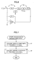
- Fig. 7 is a main flowchart illustrating the flow of operations of the skin condition estimating apparatus in the constant acquiring mode.
- Fig. 8 is a main flowchart illustrating the flow of operations of the skin condition estimating apparatus in the measuring mode.
- Fig. 9 is a subroutine flowchart illustrating the flow of operations of the skin condition estimating apparatus in the constant acquiring mode.
- Fig. 10 is a subroutine flowchart illustrating the flow of operations of the skin condition estimating apparatus in the measuring mode.
-
- A skin condition estimating apparatus according to the present invention will be described in detail with reference to a functional constitution block diagram shown in Fig. 1, a bioelectrical equivalent model diagram shown in Fig. 2, and a diagram shown in Fig. 3 which illustrates a vector locus of impedances dependent on frequencies. As shown in Fig. 1, the skin condition estimating apparatus according to the present invention comprises impedance measuring means, biological equivalent model associated parameter estimating means, and skin condition estimating means.
- The impedance measuring means has electrodes to make contact with a body and passes alternating currents of multiple frequencies through the body when the body is in contact with the electrodes to measure a contact impedance and an internal impedance which occur during the energization. More specifically, the impedance measuring means comprises a measuring section, a computing equation storing section, a constant computing section, a constant storing section, a contact impedance computing section and an internal impedance computing section and measures a contact impedance value and an internal impedance value.
- The measuring section has a plurality of electrodes and an internal standard impedance and measures the following voltage values, i.e., (i) a first external standard voltage value generated between both ends of a first external standard impedance and a first internal standard voltage value generated between both ends of the internal standard impedance when the first external standard impedance is in contact with the electrodes, (ii) a second external standard voltage value generated between both ends of a second external standard impedance and a second internal standard voltage value generated between both ends of the internal standard impedance when the second external standard impedance is in contact with the electrodes, (iii) a third external standard voltage value generated between both ends of the first external standard impedance and a third internal standard voltage value generated between both ends of the internal standard impedance when the first external standard impedance and the third external standard impedance are in contact with the electrodes and (iv) a body voltage value generated between body parts in contact with the electrodes and a fourth internal standard voltage value generated between both ends of the internal standard impedance when a body is in contact with the electrodes. An internal impedance component of a body is assumed for the first external standard impedance and the second external standard impedance, and a contact impedance component is assumed for the third external standard impedance.
- The computing equation storing section stores the following computing equations, i.e., (i) a first external standard impedance computing equation for computing a first external standard impedance value based on variation constants based on impedance variation factors, a first external standard voltage value and a first internal standard voltage value, (ii) a second external standard impedance computing equation for computing a second external standard impedance value based on the variation constants based on impedance variation factors, a second external standard voltage value and a second internal standard voltage value, (iii) an inclination computing equation for computing an inclination constant of an internal external standard impedance relationship based on the first external standard impedance value, the second external standard impedance value, a third external standard impedance value, a third internal standard voltage value and a second internal standard voltage value, (iv) a total impedance computing equation for computing a total impedance in measuring a body based on the inclination constant of the internal external standard impedance relationship, a fourth internal standard voltage value and a section constant (second internal standard voltage value) of the internal external standard impedance relationship, (v) a first provisional internal impedance computing equation for computing a provisional internal impedance in measuring the body based on the variation constants based on impedance variation factors, a body voltage value and the fourth internal standard voltage value, (vi) a body contact impedance computing equation for computing a contact impedance value in measuring the body based on the total impedance value and the provisional internal impedance value in measuring the body, (vii) a second provisional internal impedance computing equation for computing a provisional internal impedance value in measuring the first external standard impedance and the third external standard impedance based on the variation constants based on impedance variation factors, the third internal standard voltage value and a third external standard voltage value, (viii) an external standard contact impedance computing equation for computing a contact impedance value in measuring the external standard impedance based on the provisional internal impedance value in measuring the first external standard impedance and the third external standard impedance, the first external standard impedance value and the third external standard impedance value, (ix) an external standard impedance computing equation for computing a first external standard impedance value based on the provisional internal impedance value in measuring the first external standard impedance and the third external standard impedance, the contact impedance value in measuring the external standard impedance and a correction constant, and (x) an internal impedance computing equation for computing an internal impedance value in measuring the body based on the contact impedance value in measuring the body, the provisional internal impedance value in measuring the body and the correction constant. The first external standard impedance value, the second external standard impedance value, the third external standard impedance value and the internal standard impedance in the first external standard impedance computing equation, the second external standard impedance computing equation, the inclination computing equation, the external standard contact impedance computing equation and the external standard impedance computing equation are default values determined based on values expected in measuring a body.
- The constant computing section computes the following constants. That is, the constant computing section computes (i) the variation constants based on impedance variation factors by substituting the first external standard voltage value and the first internal standard voltage value which have been measured by the measuring section into the first external standard impedance computing equation stored in the computing equation storing section and substituting the second external standard voltage value and the second internal standard voltage value which have been measured by the measuring section into the second external standard impedance computing equation stored in the computing equation storing section, (ii) the inclination constant of the internal external standard impedance relationship by substituting the third internal standard voltage value and the second internal standard voltage value which have been measured by the measuring section into the inclination computing equation stored in the computing equation storing section, and (iii) the correction constant by substituting the provisional internal impedance value in measuring the first external standard impedance and the third external standard impedance and the contact impedance value in measuring the external standard impedance which have been computed by the contact impedance computing section into the external standard impedance computing equation stored in the computing equation storing section.
- The constant storing section stores the following constants, i.e., (i) the variation constants based on impedance variation factors which have been computed by the constant computing section, (ii) the inclination constant of the internal external standard impedance relationship which has been computed by the constant computing section, (iii) the second internal standard voltage value (section constant of the internal external standard impedance relationship) measured by the measuring section, and (iv) the correction constant computed by the constant computing section.
- The contact impedance computing section computes the following impedance values, i.e., (i) the total impedance value in measuring the body by substituting the inclination constant of the internal external standard impedance relationship which has been stored in the constant storing section and the fourth internal standard voltage value and the second internal standard voltage value which have been measured by the measuring section into the total impedance computing equation stored in the computing equation storing section, (ii) the provisional internal impedance value in measuring the body by substituting the variation constants based on impedance variation factors which have been stored in the constant storing section and the body voltage value and the fourth internal standard voltage value which have been measured by the measuring section into the first provisional internal impedance computing equation stored in the computing equation storing section, (iii) the contact impedance value in measuring the body by substituting the above computed total impedance value in measuring the body and provisional internal impedance value in measuring the body into the body contact impedance computing equation stored in the computing equation storing section, (iv) the provisional internal impedance value in measuring the first external standard impedance and the third external standard impedance by substituting the third external standard voltage value and the third internal standard voltage value which have been measured by the measuring section and the variation constants based on impedance variation factors which have been stored in the constant storing section into the second provisional internal impedance computing equation stored in the computing equation storing section, and (v) the contact impedance (resistance component and reactance component) value in measuring the external standard impedance by substituting the provisional internal impedance value in measuring the first external standard impedance and the third external standard impedance into the external standard contact impedance computing equation stored in the computing equation storing section.
- The internal impedance computing section computes the internal impedance (resistance component and reactance component) value in measuring the body by substituting the contact impedance value in measuring the body and the provisional internal impedance value in measuring the body which have been computed by the body contact impedance computing section and the correction constant stored in the constant storing section into the internal impedance computing equation stored in the computing equation storing section.
- The biological equivalent model associated parameter estimating means estimates parameters associated with an equivalent model constituting a living tissue based on the frequencies of the currents passed by the impedance measuring means and the measured internal impedance (resistance component and reactance component). More specifically, the biological equivalent model associated parameter estimating means comprises the computing equation storing section (which is shared by the impedance measuring means) and an equivalent model associated parameter computing section. The equivalent model associated parameter computing section computes the values of an extracellular fluid resistance Re, an intracellular fluid resistance Ri and distributed membrane capacitance Cm as shown in Fig. 2 as parameters associated with an equivalent model constituting a living tissue by substituting the internal impedance value computed in the internal impedance computing section, the frequency of the current passed by the impedance measuring means and the like into a biological equivalent model associated parameter computing equation stored in the computing equation storing section and computes the value of an angle (1 or 2) formed by the real part axis and a straight line which connects the real part axis with the internal impedance ZB50 measured when a vector locus corresponding to internal impedances measured by the impedance measuring means using alternating currents of multiple frequencies is drawn on the real part axis and the imaginary part axis based on the arc law representing a vector locus of impedances dependent on frequencies and the value of a parallel combined resistance R∞ (= Re//Ri) of the extracellular fluid resistance and the intracellular fluid resistance as shown in Fig. 3 as parameters associated with an equivalent model constituting a living tissue by use of the above computed values, the internal impedance value computed in the internal impedance computing section and the frequency of the current passed by the impedance measuring means.
- The skin condition estimating means estimates a skin condition based on at least one of the contact impedance measured by the impedance measuring means, the internal impedance measured by the impedance measuring means and the parameters associated with an equivalent model constituting a living tissue which have been estimated by the biological equivalent model associated parameter estimating means. More specifically, the skin condition estimating means comprises the computing equation storing section (which is shared by the impedance measuring means) and a skin condition computing section. The skin condition computing section computes the values of moisture (or dryness), resilience (or swelling), texture, oiliness (or gloss) and the like as characteristics representing a skin condition by substituting the contact impedance computed in the contact impedance computing section, the internal impedance value measured by the impedance measuring means, the internal impedance value computed in the internal impedance computing section and the values of the extracellular fluid resistance Re, intracellular fluid resistance Ri, distributed membrane capacitance Cm, angle and parallel combined resistance R∞ which have been computed in the equivalent model associated parameter computing section into skin condition computing equations stored in the computing equation storing section.
- In the above embodiment, it is also possible that the biological equivalent model associated parameter estimating means is omitted and the characteristics representing a skin condition are estimated by use of only the internal impedance (resistance component and reactance component) value measured by the impedance measuring means in the skin condition estimating means.
- Hereinafter, a specific example of the skin condition estimating apparatus according to the present invention will be described.
- First, a specific constitution of the skin condition estimating apparatus according to the present invention will be described by use of an external view shown in Fig. 4, a structural block diagram shown in Fig. 5 and a circuit model diagram shown in Fig. 6.
- The skin condition estimating apparatus comprises a
chassis 51, agrip 52, and acord 53 which connects thegrip 52 to thechassis 51. Thechassis 51 comprises ameasuring section 1 excludingelectrodes A 11 andB 12, anEEPROM 2, amicrocontroller 3, adisplay section 4, an input section 6 (comprising apower key 6a, a selection key 6b and a setting key 6c), and apower supply section 7. Thegrip 52 comprises the electrodes A 11 and theelectrodes B 12. - Of these sections constituting the skin condition estimating apparatus, the measuring
section 1 measures a voltage value based on an impedance for a body, an external standard impedance (resistance) or an internal standard impedance (resistance). The measuringsection 1 comprises a constant voltage (sinusoidal alternating current)generator 8, a V/I converter 9, an internalstandard impedance 10, the electrodes A 11, theelectrodes B 12, aswitcher 13, anamplifier 14, afilter 15, and an A/D converter 16. In the present example, three 800-Ω resistances and one 200-Ω resistance are used for the external standard impedance, and one 800-Ω resistance is used for the internalstandard impedance 10. These resistance values are determined based on values expected at the time of measurement of body (skin layer) . - Of these sections constituting the measuring
section 1, the constant voltage (sinusoidal alternating current)generator 8 generates a high-frequency constant voltage. The V/I converter 9 converts a constant voltage received from the constant voltage (sinusoidal alternating current)generator 8 into a constant current. - The internal
standard impedance 10 is referred to as a standard for correcting a change in constant current which is caused by a change in the temperature of an environment or the like, stray capacitance and a contact impedance which occurs when a body makes contact with the electrodes. - The electrodes A 11 are terminals for passing a constant current which is output from the V/
I converter 9 and passed through the internalstandard impedance 10 through a body or the external standard impedance. Theelectrodes B 12 are terminals for detecting a voltage generated in the body or external standard impedance. Theelectrodes A 11 andB 12 are disposed on an end face of thegrip 52 which is not connected thecord 53. - The
switcher 13 switches between detection of voltage value generated between both ends of the internal standard impedance when a constant current passes through the internalstandard impedance 10 and detection of voltage value generated between the two electrodes B when a constant current passes through a body between the two electrodes B or the external standard impedance. More specifically, theswitcher 13 switches (i) between detection of first external standard voltage value generated between both ends of the first external standard impedance and detection of first internal standard voltage value generated between both ends of the internal standard impedance when the first external standard impedance is in contact with the electrodes, (ii) between detection of second external standard voltage value generated between both ends of the second external standard impedance and detection of second internal standard voltage value generated between both ends of the internal standard impedance when the second external standard impedance is in contact with the electrodes, (iii) between detection of third external standard voltage value generated between both ends of the first external standard impedance and detection of third internal standard voltage value generated between both ends of the internal standard impedance when the first external standard impedance and the third external standard impedance are in contact with the electrodes and (iv) between detection of body voltage value generated between body parts in contact with the electrodes and detection of fourth internal standard voltage value generated between both ends of the internal standard impedance when a body is in contact with the electrodes. - After the
switcher 13, theamplifier 14 amplifies the voltage value based on the impedance of the internalstandard impedance 10 or the voltage value based on the impedance of the body or external standard impedance. Thefilter 15 removes a noise component from the voltage amplified by theamplifier 14. The A/D converter 16 digitizes the voltage (analog) denoised by thefilter 15. - Of these sections constituting the skin condition estimating apparatus, the
EEPROM 2 comprises a computingequation storing section 17 and aconstant storing section 18 and stores various computing equations and various constants in advance. More specifically, theEEPROM 2 stores: - (i) a first external standard impedance computing equation:
- (ii) a second external standard impedance computing equation:
- (iii) an inclination computing equation:
wherein ZO1 (default = 800 Ω) represents a first external standard impedance value, ZO3 (default = 800 Ω) represents a third external standard impedance value, ZO2 (default = 200 Ω) represents a second external standard impedance value, VR3 represents a third internal standard voltage value, VR2 represents a second internal standard voltage value, and p represents an inclination constant of an internal external standard impedance relationship,

- (iv) a total impedance computing equation:
- (v) a first provisional internal impedance computing equation:
- (vi) a body contact impedance computing equation:
- (vii) a second provisional internal impedance computing
equation:
- (viii) an external standard contact impedance computing
equation:
wherein ZO1 (default = 800 Ω) represents a first external standard impedance value, ZO3 (default = 800 Ω) represents a third external standard impedance, ZO1-TEMP represents a provisional internal impedance value in measuring a first external standard impedance and a third external standard impedance, and ZCO represents a contact impedance value in measuring an external standard,

- (ix) an external standard impedance computing equation:
- (x) an internal impedance computing equation:
- (xi) a biological equivalent model associated parameter
computing equation:
- (xii) skin condition computing equations:
-
- The above first external standard impedance computing equation, second external standard impedance computing equation, first provisional internal impedance computing equation and second provisional internal impedance computing equation are derived from the circuit model in Fig. 6 taking into consideration variations based on impedance variation factors which occur in the
measuring section 1. In Fig. 6, ZR represents an internal standard impedance, ZC represents a contact impedance in measuring a body, ZB represents an internal impedance in measuring the body, ZTOTAL represents a total impedance in measuring the body, ZS represents an impedance by stray capacitance or the like, ZP represents a parasitic impedance, VO represents a voltage occurring over the internal standard impedance and the body, IC represents a constant current, and AMP represents a circuit related to voltage detection. The variation constant c based on impedance variation factors is a scale factor variation constant, and the variation constant os based on impedance variation factors is an offset voltage variation factor. Further, the biological equivalent model associated parameter computing equation is derived from the bioelectrical equivalent model in Fig. 2 assumed from a fact that the frequency domain in passing a current through a living body is attributable to a biological structure of extracellular electrolyte/cell membrane/intracellular electrolyte. Further, the skin condition computing equations are derived by classifying skin conditions into sensory characteristics (moisture (or dryness), resilience (or swelling), texture, oiliness (or gloss)) and determining the relationships in between these sensory characteristics and resistance and reactance components in contact and internal impedances and parameters (Re, Ri, Cm, R∞, ) associated with an equivalent model constituting a living tissue for a number of subjects. - Of these sections constituting the skin condition estimating apparatus, the
microcontroller 3 comprises theconstant computing section 19 which computes the variation constants, inclination constant and correction constant, a contactimpedance computing section 20 which computes the total impedance value in measuring the body, the provisional internal impedance value in measuring the body, the contact impedance value in measuring the body, the provisional internal impedance value in measuring the first external standard impedance and the third external impedance and the contact impedance value in measuring the external standard impedance, an internalimpedance computing section 21 which computes the internal impedance value in measuring the body, a biological equivalent model associated parameter computing section 22 which computes the parameters associated with the equivalent model constituting the living tissue, and a skin condition computing section 23 which computes a skin condition and performs various computations, controls and internal storages. Specific operations in theconstant computing section 19, the contactimpedance computing section 20, the internalimpedance computing section 21, the biological equivalent model associated parameter computing section 22 and the skin condition computing section 23 will be described in the following description of the operations of the skin condition estimating apparatus according to the present invention. - Of these sections constituting the skin condition estimating apparatus, the
display section 4 displays results computed by themicrocontroller 3 and other data. Theinput section 6 turns on power and switches to a constant acquiring mode. Thepower supply section 7 supplies electric power to each section of the electrical system based on a signal from theinput section 6. - Next, specific operations of the skin condition estimating apparatus according to the present invention will be described by use of a main flowchart in the constant acquiring mode shown in Fig. 7, a main flowchart in a measuring mode shown in Fig. 8, a subroutine flowchart in the constant acquiring mode shown in Fig. 9 and a subroutine flowchart in the measuring mode shown in Fig. 10.
- The skin condition estimating apparatus acquires various constants prior to measurements of contact impedance and internal impedance. In accordance with the flowchart shown in Fig. 7, the apparatus acquires various constants in making measurements with an alternating current of 50 kHz (STEP S1) first and then acquires various constants in making measurements with an alternating current of 6.25 kHz (STEP S2) .
- In these steps, the same operations are performed in accordance with the flowchart shown in Fig. 9 at different frequencies.
- First, when the skin condition estimating apparatus is switched to the constant acquiring mode by the
input section 6 and only the first external standard impedance (ZO1 = 800 Ω) is connected to the electrodes A and B (STEP S21) , a voltage value between both ends (i.e., between m and n in Fig. 5) of the internal standard impedance (ZR = 800 Ω) is measured as the first internal standard voltage value VR1 (STEP S22) and a voltage value between both ends (i.e., between b and c in Fig. 5) of the first external standard impedance (ZO1 = 800 Ω) is measured as the first external standard voltage value VO1 (STEP S23) in themeasuring section 1. - Then, when only the second external standard impedance (ZO2 = 200 Ω) is connected to the electrodes A and B (STEP S24) , a voltage value between both ends (i.e., between m and n in Fig. 5) of the internal standard impedance (ZR = 800 Ω) is measured as the second internal standard voltage value VR2 (STEP S25) and a voltage value between both ends (i.e., between f and g in Fig. 5) of the second external standard impedance (ZO2 = 200 Ω) is measured as the second external standard voltage value VO2 (STEP S26) in the
measuring section 1. The second external standard voltage value Vo2 is stored in the constant storing section 18 (STEP S27). - Then, in the
constant computing section 19, the first external standard voltage value VO1 and the first internal standard voltage value VR1 which have been measured in themeasuring section 1 are substituted into the first external standard impedance computing equation stored in advance in the computingequation storing section 17, the second external standard voltage value VO2 and the second internal standard voltage value VR2 which have been measured in themeasuring section 1 are substituted into the second external standard impedance computing equation stored in the computingequation storing section 17, and the two computing equations are solved as simultaneous equations so as to compute the variation constants c and os based on impedance variation factors (STEP S28). The variation constants c and os based on impedance variation factors are stored in the constant storing section 18 (STEP S29) . - Then, when the first external standard impedance (ZO1 = 800 Ω) and the third external standard impedance (ZO3 = 800 Ω) are connected to the electrodes A and B (STEP S30) , a voltage value between both ends (i.e., between m and n in Fig. 5) of the internal standard impedance (ZR = 800 Ω) is measured as the third internal standard voltage value VR3 (STEP S31) and a voltage value between both ends (i.e., between j and k in Fig. 5) of the first external standard impedance (ZO1 = 800 Ω) is measured as the third external standard voltage value VO3 (STEP S32) in the
measuring section 1. - Then, in the
constant computing section 19, the third internal standard voltage value VR3 and the second internal standard voltage value VR2 which have been measured in themeasuring section 1 are substituted into the inclination computing equation stored in the computingequation storing section 17 so as to compute the inclination constant p (STEP S33). The inclination constant p is stored in the constant storing section 18 (STEP S34). - Then, in the contact
impedance computing section 20, the third external standard voltage value VO3 and the third internal standard voltage value VR3 which have been measured in themeasuring section 1 and the variation constants c and os based on impedance variation factors which are stored in theconstant storing section 18 are substituted into the second provisional internal impedance computing equation stored in the computingequation storing section 17 so as to compute the provisional internal impedance value ZO1-TEMP in measuring the first external standard impedance and the third external standard impedance (STEP S35) . - Then, in the contact
impedance computing section 20, the provisional internal impedance value ZO1-TEMP in measuring the first external standard impedance and the third external standard impedance is substituted into the external standard contact impedance computing equation stored in the computingequation storing section 17 so as to compute the contact impedance value ZCO in measuring the external standard in measuring the first external standard impedance and the third external standard impedance (STEP S36). - Then, in the
constant computing section 19, the contact impedance value ZCO and the provisional internal impedance value ZO1-TEMP which have been computed in the contactimpedance computing section 20 are substituted into the external standard impedance computing equation stored in the computingequation storing section 17 so as to compute the correction constant k (STEP S37) which is then stored in the constant storing section 18 (STEP S38), thereby ending the constant acquiring mode. - After acquiring various constants required to determine a contact impedance value and an internal impedance value, the skin condition estimating apparatus executes processes to determine a skin condition in accordance with the flowcharts shown in Figs. 8 and 10, unless switched to the constant acquiring mode.
- As shown in the flowchart of Fig. 8, in the impedance measuring means, a contact impedance value ZC50 (RC50, XC50) and an internal impedance value ZB50 (RB50, XB50) in making measurements with an alternating current of 50 kHz are acquired (STEP S11), and a contact impedance value ZC6.25 (RC6.25. XC6.25) and an internal impedance value ZB6.25 (RB6.25, XB6.25) in making measurements with an alternating current of 6.25 kHz are acquired (STEP S12). Details of these acquiring processes will be described later by use of Fig. 10.
- Then, in the biological equivalent model associated parameter computing section 22, the internal impedance value ZB50 (RB50, XB50) or ZB6.25 (RB6.25, XB6.25) acquired by the impedance measuring means is substituted into the internal impedance ZB (= RB + j × XB) of the biological equivalent model associated parameter computing equation stored in the computing
equation storing section 17 and a frequency of 50 kHz or 6.25 kHz is substituted into the frequency f of the above equation so as to formulate four equations, and the four equations are solved as simultaneous equations so as to compute the values of the extracellular fluid resistance Re, intracellular fluid resistance Ri and distributed membrane capacitance Cm. Further, the value of an angle (1 or 2) formed by the real part axis and a straight line which connects the real part axis with the internal impedance ZB50 measured when a vector locus corresponding to internal impedances measured by the impedance measuring means using alternating currents of multiple frequencies (50 kHz and 6.25 kHz) as shown in Fig. 3 is drawn on the real part axis and the imaginary part axis based on the arc law (cole-cole's arc law) representing a vector locus of impedances dependent on frequencies, and the value of the parallel combined resistance R∞ (= Re//Ri) of the extracellular fluid resistance and the intracellular fluid resistance are calculated (STEP S13). - Then, in the skin condition computing section 23, the values of the resistance components RC50 and RC6.25 and reactance components XC50 and XC6.25 of the contact impedances and the resistance components RB50 and RB6.25 and reactance components XB50 and XB6.25 of the internal impedances which have been acquired by the impedance measuring means and the values of the extracellular fluid resistance Re, intracellular fluid resistance Ri, distributed membrane capacitance Cm, angle (1 or 2) and parallel combined resistance R∞ (= Re//Ri) which have been computed in the biological equivalent model associated parameter computing section 22 are substituted into the skin condition computing equations stored in the computing
equation storing section 17 so as to compute the values of the moisture (or dryness) Fw, resilience (or swelling) Ft, texture Fs and oiliness (or gloss) Ff (STEP S14). These values are displayed on the display section 4 (STEP S15), thereby ending a series of operations. - In the above STEPS S11 and S12 in the flowchart of Fig. 8, the same operations are performed in accordance with the flowchart shown in Fig. 10 at different frequencies.
- First, immediately after power is turn on or after the constant acquiring mode, the skin condition estimating apparatus enters the measuring mode and retrieves the variation constants c and os, the inclination constant p, the section constant q and the correction constant k which are stored in the
constant storing section 18 in the contact impedance computing section 20 (STEP S41). - Then, when the
grip 52 is applied to the skin so that the skin makes contact with the electrodes, the voltage value of the skin layer is measured as the body voltage value VHUM (STEP S42) and a voltage value between both ends (i.e. , between m and n in Fig. 1) of the internal standard impedance (ZR = 800 Ω) is measured as the fourth internal standard voltage value VR4 (STEP S43) in themeasuring section 1. - Then, in the contact
impedance computing section 20, the fourth internal standard voltage value VR4 measured in themeasuring section 1 and the inclination constant p and the section constant q (= second internal standard voltage value VR2) which have been retrieved from theconstant storing section 18 are substituted into the total impedance computing equation stored in advance in the computing equation storing section so as to compute the total impedance value ZTOTAL in measuring the body (STEP S44). - Then, in the contact
impedance computing section 20, the body voltage value VHUM and the fourth internal standard voltage value VR4 which have been measured in themeasuring section 1 and the variation constants c and os based on impedance variation factors which have been retrieved from theconstant storing section 18 are substituted into the first provisional internal impedance computing equation stored in advance in the computing equation storing section so as to compute the provisional internal impedance value ZB-TEMP in measuring the body (STEP S45) . - Then, in the contact
impedance computing section 20, the above computed total impedance value ZTOTAL and provisional internal impedance value ZB-TEMP in measuring the body are substituted into the body contact impedance computing equation stored in advance in the computing equation storing section so as to compute the contact impedance value ZC in measuring the body. - Then, in the internal
impedance computing section 21, the contact impedance value ZC in measuring the body and the provisional internal impedance value ZB-TEMP in measuring the body which have been computed in the contactimpedance computing section 20 and the correction constant k retrieved from theconstant storing section 18 are substituted into the internal impedance computing equation stored in advance in the computing equation storing section so as to compute the internal impedance value ZB in measuring the body (STEP S47) .
the impedance measuring means has electrodes to make contact with a body and passes alternating currents of multiple frequencies through the body when the body is in contact with the electrodes to measure a contact impedance and an internal impedance which occur during the energization, and the skin condition estimating means estimates a skin condition based on at least one of the contact impedance measured by the impedance measuring means and the internal impedance measured by the impedance measuring means.
Claims (7)
- A skin condition estimating apparatus comprising:whereinimpedance measuring means, andskin condition estimating means,
the impedance measuring means has electrodes to make contact with a body and passes alternating currents of multiple frequencies through the body when the body is in contact with the electrodes to measure a contact impedance and an internal impedance which occur during the energization, and
the skin condition estimating means estimates a skin condition based on at least one of the contact impedance measured by the impedance measuring means and the internal impedance measured by the impedance measuring means. - The apparatus of claim 1, further comprising biological equivalent model associated parameter estimating means,
wherein
the biological equivalent model associated parameter estimating means estimates parameters associated with an equivalent model constituting a living tissue based on the frequencies of the currents passed by the impedance measuring means and the measured internal impedance, and
the skin condition estimating means estimates a skin condition based on at least one of the contact impedance measured by the impedance measuring means, the internal impedance measured by the impedance measuring means and the parameters estimated by the biological equivalent model associated parameter estimating means. - The apparatus of claim 2, wherein the parameters associated with the equivalent model constituting the living tissue are an extracellular fluid resistance, an intracellular fluid resistance, distributed membrane capacitance, a parallel combined resistance of the extracellular fluid resistance and the intracellular fluid resistance, and an angle formed by the real part axis and a straight line which connects the real part axis with an internal impedance measured when a vector locus corresponding to the internal impedances measured by the impedance measuring means using the alternating currents of multiple frequencies is drawn on the real part axis and the imaginary part axis based on the arc law representing a vector locus of impedances dependent on frequencies.
- The apparatus of claim 3, wherein the biological equivalent model associated parameter estimating means estimates the extracellular fluid resistance, the intracellular fluid resistance and the distributed membrane capacitance by use of the following equation:
- The apparatus of claim 3 or 4, wherein the alternating currents of multiple frequencies are an alternating current of 50 kHz and an alternating current of 6.25 kHz.
- The apparatus of claim 5, wherein the skin condition estimating means estimates at least one characteristic selected from the group consisting of moisture (or dryness), resilience (or swelling), texture and oiliness (or gloss) as a skin condition.
- The apparatus of claim 6, wherein the skin condition estimating means estimates moisture (or dryness), resilience (or swelling), texture and oiliness (or gloss) by use of the following equations:
Applications Claiming Priority (2)
| Application Number | Priority Date | Filing Date | Title |
|---|---|---|---|
| JP2004072285A JP2005253840A (en) | 2004-03-15 | 2004-03-15 | Skin condition estimation device |
| JP2004072285 | 2004-03-15 |
Publications (2)
| Publication Number | Publication Date |
|---|---|
| EP1576922A1 true EP1576922A1 (en) | 2005-09-21 |
| EP1576922B1 EP1576922B1 (en) | 2007-08-22 |
Family
ID=34836487
Family Applications (1)
| Application Number | Title | Priority Date | Filing Date |
|---|---|---|---|
| EP05003677A Expired - Lifetime EP1576922B1 (en) | 2004-03-15 | 2005-02-21 | Skin condition estimating apparatus |
Country Status (4)
| Country | Link |
|---|---|
| US (1) | US20050203435A1 (en) |
| EP (1) | EP1576922B1 (en) |
| JP (1) | JP2005253840A (en) |
| DE (1) | DE602005002066T2 (en) |
Cited By (2)
| Publication number | Priority date | Publication date | Assignee | Title |
|---|---|---|---|---|
| EP2354771A1 (en) * | 2010-02-09 | 2011-08-10 | Leifheit AG | Body analysis scales |
| ITPI20110049A1 (en) * | 2011-04-29 | 2012-10-30 | Akern S R L | A DEVICE AND ITS METHOD FOR CALCULATING THE SKIN IMPEDANCE. |
Families Citing this family (53)
| Publication number | Priority date | Publication date | Assignee | Title |
|---|---|---|---|---|
| AUPQ113799A0 (en) | 1999-06-22 | 1999-07-15 | University Of Queensland, The | A method and device for measuring lymphoedema |
| WO2005122888A1 (en) | 2004-06-18 | 2005-12-29 | The University Of Queensland | Oedema detection |
| US8068906B2 (en) * | 2004-06-21 | 2011-11-29 | Aorora Technologies Pty Ltd | Cardiac monitoring system |
| US7869865B2 (en) * | 2005-01-07 | 2011-01-11 | Biosense Webster, Inc. | Current-based position sensing |
| US7155269B2 (en) * | 2005-03-11 | 2006-12-26 | Tanita Corporation | Stress evaluation apparatus |
| CA2609111C (en) | 2005-07-01 | 2016-10-18 | Scott Chetham | A method and apparatus for performing impedance measurements in accordance with determining an electrode arrangement using a displayed representation |
| EP2250963A3 (en) * | 2005-07-01 | 2012-02-29 | Intersection Medical, Inc. | Pulmonary monitoring system |
| AU2006265761B2 (en) | 2005-07-01 | 2011-08-11 | Impedimed Limited | Monitoring system |
| JP5161772B2 (en) | 2005-08-02 | 2013-03-13 | インぺディメッド リミテッド | Impedance parameter value |
| ES2476999T3 (en) | 2005-10-11 | 2014-07-15 | Impedimed Limited | Hydration Status Monitoring |
| CA2653406C (en) | 2006-05-30 | 2015-03-17 | The University Of Queensland | Impedance measurements |
| WO2008064426A1 (en) | 2006-11-30 | 2008-06-05 | Impedimed Limited | Measurement apparatus |
| AU2008207332B2 (en) | 2007-01-15 | 2013-05-23 | Impedimed Limited | Monitoring system |
| WO2008119166A1 (en) | 2007-03-30 | 2008-10-09 | Z-Tech (Canada) Inc. | Active guarding for reduction of resistive and capactive signal loading with adjustable control of compensation level |
| CA2684324C (en) | 2007-04-20 | 2017-05-30 | Impedimed Limited | Monitoring system and probe |
| WO2009036333A1 (en) | 2007-09-14 | 2009-03-19 | Corventis, Inc. | Dynamic pairing of patients to data collection gateways |
| EP2194864B1 (en) | 2007-09-14 | 2018-08-29 | Medtronic Monitoring, Inc. | System and methods for wireless body fluid monitoring |
| US8591430B2 (en) | 2007-09-14 | 2013-11-26 | Corventis, Inc. | Adherent device for respiratory monitoring |
| WO2009036306A1 (en) | 2007-09-14 | 2009-03-19 | Corventis, Inc. | Adherent cardiac monitor with advanced sensing capabilities |
| US8116841B2 (en) | 2007-09-14 | 2012-02-14 | Corventis, Inc. | Adherent device with multiple physiological sensors |
| WO2009036256A1 (en) | 2007-09-14 | 2009-03-19 | Corventis, Inc. | Injectable physiological monitoring system |
| US8897868B2 (en) | 2007-09-14 | 2014-11-25 | Medtronic, Inc. | Medical device automatic start-up upon contact to patient tissue |
| CA2704061C (en) | 2007-11-05 | 2017-06-20 | Impedimed Limited | Impedance determination |
| MX2010007982A (en) * | 2008-01-22 | 2010-09-28 | Yeda Res & Dev | METHOD AND DEVICE FOR MONITORING BREASTFEEDING. |
| AU2008207672B2 (en) | 2008-02-15 | 2013-10-31 | Impedimed Limited | Impedance Analysis |
| EP2257216B1 (en) | 2008-03-12 | 2021-04-28 | Medtronic Monitoring, Inc. | Heart failure decompensation prediction based on cardiac rhythm |
| WO2009146214A1 (en) | 2008-04-18 | 2009-12-03 | Corventis, Inc. | Method and apparatus to measure bioelectric impedance of patient tissue |
| US8358208B2 (en) | 2008-11-11 | 2013-01-22 | Infineon Technologies Ag | Method and device for sensing a body |
| JP5616900B2 (en) | 2008-11-28 | 2014-10-29 | インぺディメッド リミテッドImpedimed Limited | Impedance measurement process |
| US8790259B2 (en) | 2009-10-22 | 2014-07-29 | Corventis, Inc. | Method and apparatus for remote detection and monitoring of functional chronotropic incompetence |
| JP5643829B2 (en) | 2009-10-26 | 2014-12-17 | インぺディメッド リミテッドImpedimed Limited | Method and apparatus for use in impedance measurement analysis |
| AU2010321683B2 (en) | 2009-11-18 | 2014-06-26 | Impedimed Limited | Signal distribution for patient-electrode measurements |
| US9451897B2 (en) | 2009-12-14 | 2016-09-27 | Medtronic Monitoring, Inc. | Body adherent patch with electronics for physiologic monitoring |
| US8965498B2 (en) | 2010-04-05 | 2015-02-24 | Corventis, Inc. | Method and apparatus for personalized physiologic parameters |
| PT3581105T (en) | 2010-05-08 | 2022-10-19 | Univ California | DEVICE FOR EARLY DETECTION OF ULCER BY SUBEPIDERMAL MOISTURE SCREENING |
| US8700121B2 (en) | 2011-12-14 | 2014-04-15 | Intersection Medical, Inc. | Devices for determining the relative spatial change in subsurface resistivities across frequencies in tissue |
| CN102512169B (en) * | 2011-12-31 | 2013-06-05 | 重庆邮电大学 | Adaptive control method and device for deviation in skin electrical signal testing |
| JP6221043B2 (en) * | 2012-07-06 | 2017-11-01 | パナソニックIpマネジメント株式会社 | Skin characteristic measuring instrument and portable terminal |
| JP6210265B2 (en) * | 2012-12-05 | 2017-10-11 | パナソニックIpマネジメント株式会社 | Body composition measuring device, body composition measuring method, and correction method for body composition measuring method |
| CN105982672B (en) * | 2015-03-04 | 2021-07-06 | 林芳仪 | Skin detection method and skin detection device |
| US10182740B2 (en) | 2015-04-24 | 2019-01-22 | Bruin Biometrics, Llc | Apparatus and methods for determining damaged tissue using sub-epidermal moisture measurements |
| WO2016172264A1 (en) * | 2015-04-24 | 2016-10-27 | Bruin Biometrics Llc | Apparatus and methods for determining damaged tissue using sub-epidermal moisture measurements |
| KR101661902B1 (en) * | 2015-06-24 | 2016-10-04 | 주식회사 웨이웨어러블 | Portable device for measuring skin condition, method and program for analyzing skin condition |
| JP6900477B2 (en) | 2017-02-03 | 2021-07-07 | ブルーイン、バイオメトリクス、リミテッド、ライアビリティー、カンパニーBruin Biometrics, Llc | A device for assessing compartment syndrome and a computer-readable medium for detecting compartment syndrome |
| CN109890272B (en) | 2017-02-03 | 2022-05-17 | 布鲁恩生物有限责任公司 | Measurement of tissue viability |
| CN118177725A (en) | 2017-02-03 | 2024-06-14 | 布鲁恩医疗创新有限责任公司 | Measurement of susceptibility to diabetic foot ulcers |
| CN107678543B (en) * | 2017-09-25 | 2020-06-16 | 南昌大学 | A method for parameter estimation of human hand skin-electrode bioimpedance model based on electrotactile devices |
| KR20240159026A (en) | 2017-11-16 | 2024-11-05 | 브루인 바이오메트릭스, 엘엘씨 | Providing a continuity of care across multiple care settings |
| US11471094B2 (en) | 2018-02-09 | 2022-10-18 | Bruin Biometrics, Llc | Detection of tissue damage |
| SI3861601T1 (en) | 2018-10-11 | 2024-05-31 | Bruin Biometrics, Llc | A device with a single-use element |
| US11642075B2 (en) | 2021-02-03 | 2023-05-09 | Bruin Biometrics, Llc | Methods of treating deep and early-stage pressure induced tissue damage |
| US12611137B2 (en) * | 2021-06-25 | 2026-04-28 | Koya Medical, Inc. | Lymphatic diagnostic device |
| WO2025186309A1 (en) | 2024-03-08 | 2025-09-12 | Trinamix Gmbh | Bioimpedance device |
Citations (3)
| Publication number | Priority date | Publication date | Assignee | Title |
|---|---|---|---|---|
| EP1080686A1 (en) * | 1999-09-03 | 2001-03-07 | Tanita Corporation | Bioelectrical impedance measuring method and body composition measuring apparatus |
| JP2003169784A (en) | 2001-12-05 | 2003-06-17 | Matsushita Electric Ind Co Ltd | Body fat measurement device |
| JP2003169785A (en) | 2001-12-05 | 2003-06-17 | Matsushita Electric Ind Co Ltd | Body fat measurement device |
Family Cites Families (4)
| Publication number | Priority date | Publication date | Assignee | Title |
|---|---|---|---|---|
| JPH01126535A (en) * | 1987-11-12 | 1989-05-18 | Kao Corp | Method and apparatus for measuring content of skin moisture |
| US5086781A (en) * | 1989-11-14 | 1992-02-11 | Bookspan Mark A | Bioelectric apparatus for monitoring body fluid compartments |
| JP3699640B2 (en) * | 2000-08-01 | 2005-09-28 | 株式会社タニタ | Body water content state determination device by multi-frequency bioimpedance measurement |
| FI109651B (en) * | 2001-03-23 | 2002-09-30 | Delfin Technologies Ltd | Procedure for measuring edema in tissues |
-
2004
- 2004-03-15 JP JP2004072285A patent/JP2005253840A/en not_active Abandoned
-
2005
- 2005-02-21 EP EP05003677A patent/EP1576922B1/en not_active Expired - Lifetime
- 2005-02-21 DE DE602005002066T patent/DE602005002066T2/en not_active Expired - Lifetime
- 2005-03-07 US US11/072,300 patent/US20050203435A1/en not_active Abandoned
Patent Citations (3)
| Publication number | Priority date | Publication date | Assignee | Title |
|---|---|---|---|---|
| EP1080686A1 (en) * | 1999-09-03 | 2001-03-07 | Tanita Corporation | Bioelectrical impedance measuring method and body composition measuring apparatus |
| JP2003169784A (en) | 2001-12-05 | 2003-06-17 | Matsushita Electric Ind Co Ltd | Body fat measurement device |
| JP2003169785A (en) | 2001-12-05 | 2003-06-17 | Matsushita Electric Ind Co Ltd | Body fat measurement device |
Non-Patent Citations (3)
| Title |
|---|
| SALTER D C: "Examination of stratum corneum hydration state by electrical methods", CURRENT PROBLEMS IN DERMATOLOGY (BASEL); SKIN BIOENGINEERING: TECHNIQUES AND APPLICATIONS IN DERMATOLOGY AND COSMETOLOGY S. KARGER AG, P.O. BOX, ALLSCHWILERSTRASSE 10, CH-4009 BASEL, SWITZERLAND; S. KARGER AG, NEW YORK, NEW YORK, USA SERIES : CURRENT, 1998, pages 38 - 47, XP008048739, ISSN: 3-8055-6519-4 * |
| VILHUNEN T ET AL: "Simultaneous reconstruction of electrode contact impedances and internal electrical properties. I. Theory", MEASUREMENT SCIENCE & TECHNOLOGY IOP PUBLISHING UK, vol. 13, no. 12, December 2002 (2002-12-01), pages 1848 - 1854, XP002332619, ISSN: 0957-0233 * |
| YAMAMOTO Y ET AL: "MEASUREMENT PRINCIPLE FOR EVALUATING THE PERFORMANCE OF DRUGS AND COSMETICS BY SKIN IMPEDANCE", MED BIOL ENG COMPUT NOV 1978, vol. 16, no. 6, November 1978 (1978-11-01), pages 623 - 632, XP002332620 * |
Cited By (2)
| Publication number | Priority date | Publication date | Assignee | Title |
|---|---|---|---|---|
| EP2354771A1 (en) * | 2010-02-09 | 2011-08-10 | Leifheit AG | Body analysis scales |
| ITPI20110049A1 (en) * | 2011-04-29 | 2012-10-30 | Akern S R L | A DEVICE AND ITS METHOD FOR CALCULATING THE SKIN IMPEDANCE. |
Also Published As
| Publication number | Publication date |
|---|---|
| DE602005002066T2 (en) | 2008-05-29 |
| DE602005002066D1 (en) | 2007-10-04 |
| JP2005253840A (en) | 2005-09-22 |
| US20050203435A1 (en) | 2005-09-15 |
| EP1576922B1 (en) | 2007-08-22 |
Similar Documents
| Publication | Publication Date | Title |
|---|---|---|
| EP1576922B1 (en) | Skin condition estimating apparatus | |
| JP4064028B2 (en) | Physical fatigue assessment device | |
| US9615767B2 (en) | Fluid level indicator determination | |
| JP4646614B2 (en) | Body composition measuring device | |
| JP4024774B2 (en) | Body fat measuring device | |
| US9149235B2 (en) | Oedema detection | |
| KR100423675B1 (en) | Bioelectrical impedance measuring method and body composition measuring apparatus | |
| CA2262924C (en) | Device and method for measuring the composition of the body | |
| EP1898784B1 (en) | Method and apparatus for performing impedance measurements | |
| US20220007956A1 (en) | Evaluating impedance measurements | |
| EP1013221A1 (en) | Living body impedance measuring instrument and body composition measuring instrument | |
| US8099250B2 (en) | Impedance parameter values | |
| US7110809B2 (en) | Muscle fatigue measuring equipment | |
| JP2001070273A5 (en) | ||
| JP2001224568A (en) | Body fat measurement device | |
| WO2017008118A1 (en) | Fluid level determination | |
| JPH10185A (en) | Body fluid abnormality diagnosis device | |
| AU2011274290B2 (en) | Tissue indicator determination | |
| JP6941258B2 (en) | An arithmetic processing device and a program for evaluating the water content of the stratum corneum, an electronic device equipped with the arithmetic processing apparatus, and a method for evaluating the water content of the stratum corneum. | |
| US20050033192A1 (en) | Device for prompting to control physical condition for woman | |
| JP2001212101A (en) | Electrical property measurement device | |
| CN108652622B (en) | Method and system for automatically detecting human body components | |
| JP3984332B2 (en) | Body composition estimation device and computer-readable recording medium recording body composition estimation program | |
| JP2002153437A (en) | Body impedance measurement device | |
| KR20050105783A (en) | Measuring installation of fat in body using a mobile and measuring method thereof |
Legal Events
| Date | Code | Title | Description |
|---|---|---|---|
| PUAI | Public reference made under article 153(3) epc to a published international application that has entered the european phase |
Free format text: ORIGINAL CODE: 0009012 |
|
| 17P | Request for examination filed |
Effective date: 20050221 |
|
| AK | Designated contracting states |
Kind code of ref document: A1 Designated state(s): AT BE BG CH CY CZ DE DK EE ES FI FR GB GR HU IE IS IT LI LT LU MC NL PL PT RO SE SI SK TR |
|
| AX | Request for extension of the european patent |
Extension state: AL BA HR LV MK YU |
|
| AKX | Designation fees paid |
Designated state(s): DE FR GB |
|
| GRAP | Despatch of communication of intention to grant a patent |
Free format text: ORIGINAL CODE: EPIDOSNIGR1 |
|
| GRAS | Grant fee paid |
Free format text: ORIGINAL CODE: EPIDOSNIGR3 |
|
| GRAA | (expected) grant |
Free format text: ORIGINAL CODE: 0009210 |
|
| AK | Designated contracting states |
Kind code of ref document: B1 Designated state(s): DE FR GB |
|
| REG | Reference to a national code |
Ref country code: GB Ref legal event code: FG4D |
|
| REF | Corresponds to: |
Ref document number: 602005002066 Country of ref document: DE Date of ref document: 20071004 Kind code of ref document: P |
|
| ET | Fr: translation filed | ||
| PLBE | No opposition filed within time limit |
Free format text: ORIGINAL CODE: 0009261 |
|
| STAA | Information on the status of an ep patent application or granted ep patent |
Free format text: STATUS: NO OPPOSITION FILED WITHIN TIME LIMIT |
|
| 26N | No opposition filed |
Effective date: 20080526 |
|
| PGFP | Annual fee paid to national office [announced via postgrant information from national office to epo] |
Ref country code: FR Payment date: 20120221 Year of fee payment: 8 |
|
| PGFP | Annual fee paid to national office [announced via postgrant information from national office to epo] |
Ref country code: DE Payment date: 20120215 Year of fee payment: 8 |
|
| PGFP | Annual fee paid to national office [announced via postgrant information from national office to epo] |
Ref country code: GB Payment date: 20120215 Year of fee payment: 8 |
|
| GBPC | Gb: european patent ceased through non-payment of renewal fee |
Effective date: 20130221 |
|
| REG | Reference to a national code |
Ref country code: FR Ref legal event code: ST Effective date: 20131031 |
|
| REG | Reference to a national code |
Ref country code: DE Ref legal event code: R119 Ref document number: 602005002066 Country of ref document: DE Effective date: 20130903 |
|
| PG25 | Lapsed in a contracting state [announced via postgrant information from national office to epo] |
Ref country code: GB Free format text: LAPSE BECAUSE OF NON-PAYMENT OF DUE FEES Effective date: 20130221 Ref country code: DE Free format text: LAPSE BECAUSE OF NON-PAYMENT OF DUE FEES Effective date: 20130903 Ref country code: FR Free format text: LAPSE BECAUSE OF NON-PAYMENT OF DUE FEES Effective date: 20130228 |