EP1576741A1 - A calibrating method for time-varying channel in a time-slot division mobile communication system - Google Patents
A calibrating method for time-varying channel in a time-slot division mobile communication system Download PDFInfo
- Publication number
- EP1576741A1 EP1576741A1 EP03788747A EP03788747A EP1576741A1 EP 1576741 A1 EP1576741 A1 EP 1576741A1 EP 03788747 A EP03788747 A EP 03788747A EP 03788747 A EP03788747 A EP 03788747A EP 1576741 A1 EP1576741 A1 EP 1576741A1
- Authority
- EP
- European Patent Office
- Prior art keywords
- channel
- deviation
- time
- varying
- channel estimation
- Prior art date
- Legal status (The legal status is an assumption and is not a legal conclusion. Google has not performed a legal analysis and makes no representation as to the accuracy of the status listed.)
- Granted
Links
Images

Classifications
-
- H—ELECTRICITY
- H04—ELECTRIC COMMUNICATION TECHNIQUE
- H04L—TRANSMISSION OF DIGITAL INFORMATION, e.g. TELEGRAPHIC COMMUNICATION
- H04L25/00—Baseband systems
- H04L25/02—Details ; arrangements for supplying electrical power along data transmission lines
- H04L25/0202—Channel estimation
- H04L25/022—Channel estimation of frequency response
-
- H—ELECTRICITY
- H04—ELECTRIC COMMUNICATION TECHNIQUE
- H04J—MULTIPLEX COMMUNICATION
- H04J3/00—Time-division multiplex systems
- H04J3/02—Details
- H04J3/10—Arrangements for reducing cross-talk between channels
-
- H—ELECTRICITY
- H04—ELECTRIC COMMUNICATION TECHNIQUE
- H04B—TRANSMISSION
- H04B1/00—Details of transmission systems, not covered by a single one of groups H04B3/00 - H04B13/00; Details of transmission systems not characterised by the medium used for transmission
- H04B1/69—Spread spectrum techniques
- H04B1/707—Spread spectrum techniques using direct sequence modulation
-
- H—ELECTRICITY
- H04—ELECTRIC COMMUNICATION TECHNIQUE
- H04B—TRANSMISSION
- H04B1/00—Details of transmission systems, not covered by a single one of groups H04B3/00 - H04B13/00; Details of transmission systems not characterised by the medium used for transmission
- H04B1/69—Spread spectrum techniques
- H04B1/707—Spread spectrum techniques using direct sequence modulation
- H04B1/7097—Interference-related aspects
- H04B1/711—Interference-related aspects the interference being multi-path interference
- H04B1/7115—Constructive combining of multi-path signals, i.e. RAKE receivers
-
- H—ELECTRICITY
- H04—ELECTRIC COMMUNICATION TECHNIQUE
- H04L—TRANSMISSION OF DIGITAL INFORMATION, e.g. TELEGRAPHIC COMMUNICATION
- H04L25/00—Baseband systems
- H04L25/02—Details ; arrangements for supplying electrical power along data transmission lines
- H04L25/0202—Channel estimation
- H04L25/0224—Channel estimation using sounding signals
- H04L25/0228—Channel estimation using sounding signals with direct estimation from sounding signals
- H04L25/023—Channel estimation using sounding signals with direct estimation from sounding signals with extension to other symbols
- H04L25/0236—Channel estimation using sounding signals with direct estimation from sounding signals with extension to other symbols using estimation of the other symbols
-
- H—ELECTRICITY
- H04—ELECTRIC COMMUNICATION TECHNIQUE
- H04L—TRANSMISSION OF DIGITAL INFORMATION, e.g. TELEGRAPHIC COMMUNICATION
- H04L25/00—Baseband systems
- H04L25/02—Details ; arrangements for supplying electrical power along data transmission lines
- H04L25/0202—Channel estimation
- H04L25/024—Channel estimation channel estimation algorithms
-
- H—ELECTRICITY
- H04—ELECTRIC COMMUNICATION TECHNIQUE
- H04B—TRANSMISSION
- H04B1/00—Details of transmission systems, not covered by a single one of groups H04B3/00 - H04B13/00; Details of transmission systems not characterised by the medium used for transmission
- H04B1/69—Spread spectrum techniques
- H04B1/707—Spread spectrum techniques using direct sequence modulation
- H04B1/7097—Interference-related aspects
- H04B1/7103—Interference-related aspects the interference being multiple access interference
-
- H—ELECTRICITY
- H04—ELECTRIC COMMUNICATION TECHNIQUE
- H04B—TRANSMISSION
- H04B2201/00—Indexing scheme relating to details of transmission systems not covered by a single group of H04B3/00 - H04B13/00
- H04B2201/69—Orthogonal indexing scheme relating to spread spectrum techniques in general
- H04B2201/707—Orthogonal indexing scheme relating to spread spectrum techniques in general relating to direct sequence modulation
- H04B2201/70701—Orthogonal indexing scheme relating to spread spectrum techniques in general relating to direct sequence modulation featuring pilot assisted reception
Definitions
- the invention relates generally to the mobile communication technology, especially to a correction method for a time varying channel in a time-slot division mobile communication system.
- the invention proposes an iterative correction method for channel estimation, applicable to a time-slotted CDMA system or other similar block processing systems.
- Channel response is determined by characteristics of a transmitting device, propagation of RF carrier in a wireless channel, and a receiving device. Doppler frequency shift caused by a moving terminal, a radio propagation channel response varying, a fading varying, a frequency drift and deviation of devices etc. will lead to a time varying channel response and eventually affect performance of a system. Therefore, at the receiving end, the channel estimation and measurement must keep up with the channel varying in order to guarantee a good demodulation performance for received data.
- the channel response is time invariant.
- the assumption and other limitations bring great convenience to system design and relevant processing. Nevertheless, the assumption that the channel response is time invariant within a block has limited the application of the system, i.e. the application thereof has high requirements on frequency deviation and shift as well as on the moving speed of a terminal.
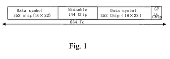
- the burst structure in a traffic time-slot in the TD-SCDMA (3GPP 1.28Mcps TDD) system is taken as an example for further description.
- a midamble at the middle of a burst signal is used for channel estimation and can be called a channel estimation code while at both sides of the midamble are traffic data fields.
- the parameters of a traffic time-slot are as follows: the time-slot length is 675 ⁇ s; the length of a symbol is 12.5 ⁇ s when the spread factor is 16; and the length of a chip is 781 ns.
- Each time-slot (or a burst signal) has two traffic data fields, each of which has 22 symbols (spread factor 16).
- each of the two traffic data fields has a total of 352 chips and a midamble of 144 (128 + 16) chips.
- the block processing method limits the system working conditions.
- the channel response varies within a time-slot, the system performance will become worse obviously.
- a phase varying caused by channel response varying will make worse the performance of demodulation that contains phase modulation signals, such as phase shift keying (PSK) and quadrature amplitude modulation (QAM); and an amplitude varying caused by channel response varying will make worse the performance of demodulation that contains amplitude modulation signals, such as QAM.
- phase modulation signals such as phase shift keying (PSK) and quadrature amplitude modulation (QAM)
- QAM quadrature amplitude modulation
- the main causes that lead to channel response varying are as follows: deviation between transmitting frequency and receiving frequency; Doppler frequency shift caused by a moving terminal and fast fading etc.
- the maximum Doppler frequency shift is 463 Hz when the terminal moving speed is 250 km/h
- the phase varying at one of the two ends of a TD-SCDMA time-slot relative to the phase at the center of the time-slot could be up to 1.25 ⁇ ⁇ /4, making it impossible to demodulate a QPSK signal.
- the limitation will become more strict when 8-PSK modulation or 16-QAM modulation is used.
- the other is the difficulty in obtaining the channel response varying: if only one channel estimation is given in one time-slot, and the two neighboring time-slots of a user are not consecutive, such as the time division duplex (TDD) system in 3GPP, then it is impossible to know the channel response varying situation from channel estimation results through interpolation and prediction.
- TDD time division duplex
- the object of the invention is to provide a correction method for time varying channel in a time-slotted mobile communication system.
- this simple and effective method is adaptive to the channel response varying in a certain degree within a time-slot.
- application scope of a time-slotted CDMA system or similar block processing systems can be enlarged and performance thereof can be improved even with a larger frequency deviation and shift in the system or a higher moving speed of the terminal.
- a correction method for time varying channels in a time slot division mobile communication system including,
- Step B demodulation of the detection result is implemented with the corrected channel estimation.
- the detection result is obtained. Part of the detection result is demodulated, and then with the demodulated result the channel deviation is estimated and corrected. In this way, the channel varying within the block is obtained. Then the detection result is demodulated again to recover the transmitted data.
- the correction method for time varying channels proposed by this invention is a simple method that can correct the channel varying which happens within a data block (field) to obtain the demodulated data. It is performed in an iterative mode along with selecting in each time of iteration a changing number of symbols that are close to the channel estimation code. With the increasing of iterative times, demodulated data increase gradually. When the set times of iteration is reached, all data are demodulated.
- the main characteristics of the invention are: performing channel estimation and signal detection with the time invariant block processing method; estimating the channel varying by using part of the symbols that are close to the channel estimation code; performing iterative corrections with the estimated deviations to obtain an increasingly accurate deviation estimation and eventually recover the transmitted data.
- the invention expands the application scope of the time slot CDMA system and other similar block processing systems, i.e. reducing the limiting conditions of the application thereof and improving the system performance when channels vary rapidly.
- the method of the invention mainly includes the following steps:
- the Steps 2 and 3 above can be executed once, e.g. for a mobile terminal, or for a plurality of times (for example, twice), e.g. for a base station.
- the embodiment is carried out in a traffic time-slot of a TD-SCDMA system, i.e. there are two data fields in a TD-SCDMA traffic time-slot.
- the implementation of channel correction is similar.
- Step 1 perform channel estimation and signal detection (Step 11) with the processing method that the channel response is time invariant within a data block (field).
- the signal detection algorithm may be a joint detection algorithm, such as Zero Forcing-Block Linear Equalization (ZF-BLE), Minimum Mean Square Error-Block Linear Equalization (MMSE-BLE) and Interference Cancellation (IC) etc., or matched filtering detection (MF) or a RAKE receiver may be used.
- ZF-BLE Zero Forcing-Block Linear Equalization
- MMSE-BLE Minimum Mean Square Error-Block Linear Equalization
- IC Interference Cancellation
- MF matched filtering detection
- RAKE receiver matched filtering detection
- the iterative correction operation takes the detection output of a block processing as the input signal (Step 12).
- the iterative times and the number of symbols M that are taken near the channel estimation code for each iteration are determined by the overhead of the algorithm and the results of simulation and practical tests (Step 13).
- the iteration is carried out twice, M of the first iteration is 8, and M of the second iteration is 16; M should be less than or equal to the total number of data symbols N in a code channel, i.e. M ⁇ N.
- N in a TD-SCDMA system is 22 (refer to Figure 1)
- d ( k ) 2 ( d ( k ) 2,1 , d ( k ) 2,2 , ⁇ , d ( k ) 2, n , ⁇ , d ( k ) 2, N )
- k 1, ...K representing the different code channels in a time-slot
- n 1, ...N representing the different symbols in a code channel, i.e. the total number of symbols in the code channel.
- Formula (1-1) is the detection result of the first data field in the burst structure
- formula (1-2) is the detection result of the second data field in the burst structure.
- Step 2 Perform demodulation and hard-decision for the detection result of some symbols (2M in number) that are near the channel estimation code (Step 22), then re-modulate the hard-decision results (Step 23), and then compare the re-modulated signal with the detection results of the 2M symbols before the demodulation to estimate the channel deviation (Step 24).
- the value of M is determined by the maximum varying of amplitude and phase allowed by the appropriate modulation mode: when the allowable varying scope of amplitude and phase is larger, a larger M is taken; and when the allowable varying scope of amplitude and phase is smaller, a smaller M is taken.
- the minimum phase difference on the constellation is ⁇ /2; the maximum allowable phase estimation error when there is no noise interference is ⁇ /4; the phase error should be less if taking into account the noise interference tolerance of a received signal, such as 0.5 ⁇ ⁇ /4.
- the minimum phase difference on the constellation is ⁇ /4; the maximum allowable phase estimation error when there is no noise interference is ⁇ /8; the phase error should be less if taking into account the noise interference tolerance of a received signal, e.g. 0.5 ⁇ ⁇ /8.
- An additional remark is that, for a multi-code-channel user, the deviation of different channels that belong to the same user, estimated at Step 24, can be averaged again to obtain a statistic mean value, which can be used to substitute the original estimated channel deviation.
- a difference method which is based on the phase difference between symbols (a relative deviation) also can be used to estimate the phase deviation of a channel. Namely, the phase difference between symbols (a relative deviation) also can be demodulated, performed hard decision on, re-modulated, and the re-modulated result is compared with the result before the demodulation to obtain the estimated phase deviation of a channel.
- Step 3 Take an approximate model of channel varying of which parameters are determined by the 2M deviations given by the 2M symbols.
- one is a linear approximate model, in which the channel varying in the whole time-slot is approximated with a linear with a fixed slope; the other is a ladder approximate model, in which the channel varying of two data fields are respectively approximated by being converted to a fixed values of the center of each data field.
- the parameter needed to be determined is the ⁇ ( K ) .
- an ⁇ ( K ) can be obtained with the formula (4-1) corresponding to each symbol, represented by ⁇ ( k ) / n , and finally the ⁇ ( K ) is:
- Step 4 With the approximate model of the channel response varying obtained in the last step, the deviation value of each symbol in each code channel can be computed. Revise the channel estimation by the obtained deviation value and correct the detective data d ( k ) / 1 and d ( k ) / 2 in the formulas (1-1) and (1-2) with the revised channel estimation to obtain the corrected data d "( k ) / 1 and d "( k ) / 2, then return to Step 21.
- the method of this invention not only an accurate deviation of a channel but also the final demodulated data of a current time-slot can be obtained for a time-slot data or a burst data.
- the method corrects deviation by comparing the detection result before demodulating some symbols that is near a channel estimation code with the result thereof after having been demodulated, decided and re-modulated.
- the method also provides an approximate model for representing the amplitude and phase of a channel response.
- the method can be used in the receiving processing of a base station and a mobile terminal.
Landscapes
- Engineering & Computer Science (AREA)
- Computer Networks & Wireless Communication (AREA)
- Signal Processing (AREA)
- Power Engineering (AREA)
- Digital Transmission Methods That Use Modulated Carrier Waves (AREA)
- Mobile Radio Communication Systems (AREA)
Abstract
Description
wherein between the said step A and step B the method further comprises,
ϕ (k) / 1,i, ϕ (k) / 2,i are phase deviation (difference).

y (k) / n is the channel deviation of the kth code channel corresponding to the time position. Suppose tn = 0 is corresponding to the center of a time-slot, then y (k) / 0 = 0.

Claims (10)
- A correction method for time varying channels in a time slot division mobile communication system including:the said detection result is demodulated in the said Step B by using the corrected channel estimation.A. performing channel estimation for a time-slot or burst signal received with a time invariant block processing method and performing signal detection by using the channel estimation result to obtain a detection result;B. demodulating the detection result to recover the transmitted data;
wherein between the said step A and step B the method further comprises,A1. estimating the channel deviation by the detection result of some symbols that are near the channel estimation code;A2. correcting the channel estimation with the estimated channel deviation; - A correction method according to Claim 1, wherein detecting the said signal in Step A is implemented by a joint detection method including a Zero Forcing-Block Linear Equalization (ZF-BLE), or a Minimum Mean Square Error-Block Linear Equalization (MMSE-BLE) or an Interference Cancellation (IC), or by a method of a matched filtering detection (MF) or a RAKE receiver.
- A correction method according to Claim 1, before executing the Step A1 further comprising, setting iterative times for repeating Steps A1 and A2; detecting before performing Step A1 whether the iterative times have been reached; if yes, going to Step B, otherwise repeating Steps A1 and A2, wherein, when Step A1 is executed, the number of symbols around the channel estimation code that are selected for the current iteration is greater than the number of symbols in the last iteration.
- A correction method according to Claim 1, wherein the said detection result of some symbols around the channel estimation code is the detection result of the selected number of data symbols, the selected number relates to the maximum varying of phase and amplitude allowed by the modulation mode adopted by the mobile communication system while the larger the allowable maximum varying of amplitude and phase, the larger the said number.
- A correction method according to Claim 1, wherein the said estimating the channel deviation in Step A1 comprises demodulating, making hard decision on, and re-modulating the detection result of the selected symbols near the channel estimation code by symbols; comparing the re-modulated result with the detection result before the demodulation to estimate the channel deviation including an amplitude deviation and a phase deviation.
- A correction method according to Claim 1, wherein the said estimating the channel deviation in Step A1 comprises, demodulating, making hard decision on, and re-modulating the detection result of the selected symbols near the channel estimation code by the phase difference between symbols, comparing the re-modulated result with the detection result before the demodulation to estimate the phase deviation of the channel.
- A correction method according to Claim 1, wherein the said estimating the channel deviation in Step A1 further comprises, for a multi-code-channel user, averaging the estimated value of the channel deviation of each code channel of the user to obtain a statistical mean value, which is used as the estimated value of the channel deviation of different code channels of the same user.
- A correction method according to Claim 1, wherein the Step A2 of correcting the channel estimation with the estimated channel deviation comprises, defining an approximate model of channel varying, the parameters of which are determined using the estimated channel deviation; computing a deviation value of each symbol in the data field with the approximate model of channel varying of which parameters have been determined, and then correcting the channel estimation with the deviation value.
- A correction method according to Claim 8, wherein the approximate model of channel varying is a linear model that approximates channel varying in one time slot with a linear line having a fixed slope.
- A correction method according to Claim 8, wherein the approximate model of channel varying is a ladder approximate model, where the channel varying of two data fields are approximated by being converted to a fixed values of the center of each data field, respectively.
Applications Claiming Priority (3)
| Application Number | Priority Date | Filing Date | Title |
|---|---|---|---|
| CNB021605009A CN1224280C (en) | 2002-12-27 | 2002-12-27 | Time-varying channel correction method for time-division slot mobile communication system |
| CN02160500 | 2002-12-27 | ||
| PCT/CN2003/001132 WO2004059859A1 (en) | 2002-12-27 | 2003-12-26 | A calibrating method for time-varying channel in a time-slot division mobile communication system |
Publications (3)
| Publication Number | Publication Date |
|---|---|
| EP1576741A1 true EP1576741A1 (en) | 2005-09-21 |
| EP1576741A4 EP1576741A4 (en) | 2011-06-22 |
| EP1576741B1 EP1576741B1 (en) | 2016-05-18 |
Family
ID=32661117
Family Applications (1)
| Application Number | Title | Priority Date | Filing Date |
|---|---|---|---|
| EP03788747.8A Expired - Lifetime EP1576741B1 (en) | 2002-12-27 | 2003-12-26 | A correction method of time-varying channel estimation in a time-slotted mobile communication system |
Country Status (7)
| Country | Link |
|---|---|
| US (1) | US7272166B2 (en) |
| EP (1) | EP1576741B1 (en) |
| JP (1) | JP4167655B2 (en) |
| KR (1) | KR100725215B1 (en) |
| CN (1) | CN1224280C (en) |
| AU (1) | AU2003296223A1 (en) |
| WO (1) | WO2004059859A1 (en) |
Cited By (1)
| Publication number | Priority date | Publication date | Assignee | Title |
|---|---|---|---|---|
| CN113497770A (en) * | 2020-04-01 | 2021-10-12 | 清华大学 | Fast time-varying channel parameter estimation method and device for OFDM system |
Families Citing this family (10)
| Publication number | Priority date | Publication date | Assignee | Title |
|---|---|---|---|---|
| KR20070090800A (en) * | 2006-03-03 | 2007-09-06 | 삼성전자주식회사 | Channel Estimation Apparatus and Method in Wireless Communication System |
| CN100512036C (en) * | 2006-11-17 | 2009-07-08 | 北京天碁科技有限公司 | Method and device for estimating channel in TD-SCDMA |
| CN101193094B (en) * | 2006-11-20 | 2011-10-19 | 电信科学技术研究院 | A method and system for sending broadcast/multicast service |
| JP2009065581A (en) * | 2007-09-10 | 2009-03-26 | Nec Corp | Wireless communication system |
| US8290091B2 (en) * | 2009-12-01 | 2012-10-16 | Telefonaktiebolaget L M Ericsson (Publ) | Method and apparatus for detecting a plurality of symbol blocks using a decoder |
| EP2769518A4 (en) * | 2011-10-19 | 2015-10-28 | Optis Cellular Technology Llc | Method and apparatus for channel predicting |
| CN103236886B (en) * | 2013-03-27 | 2015-05-06 | 大唐移动通信设备有限公司 | Method and system for detecting faults of channels of base station |
| US10244426B2 (en) * | 2014-08-19 | 2019-03-26 | Qualcomm Incorporated | Frequency error detection with PBCH frequency hypothesis |
| FR3038800A1 (en) * | 2015-07-09 | 2017-01-13 | Stmicroelectronics Rousset | METHOD FOR PROCESSING A SIGNAL FROM A TRANSMISSION CHANNEL, PARTICULARLY AN IN-LINE CARRIER CURRENT VEHICLE SIGNAL, AND ESPECIALLY CHANNEL ESTIMATION, AND CORRESPONDING RECEIVER |
| DE102018206132B4 (en) * | 2018-04-20 | 2019-11-21 | Fraunhofer-Gesellschaft zur Förderung der angewandten Forschung e.V. | Decoder-based iterative channel estimation |
Family Cites Families (10)
| Publication number | Priority date | Publication date | Assignee | Title |
|---|---|---|---|---|
| DE19614543C1 (en) * | 1996-04-12 | 1997-08-28 | Philips Patentverwaltung | Equalizer with extended channel estimation for a receiver in a digital transmission system |
| US6452917B1 (en) * | 1999-04-08 | 2002-09-17 | Qualcomm Incorporated | Channel estimation in a CDMA wireless communication system |
| US6504884B1 (en) * | 1999-05-12 | 2003-01-07 | Analog Devices, Inc. | Method for correcting DC offsets in a receiver |
| JP2001069117A (en) | 1999-08-31 | 2001-03-16 | Matsushita Electric Ind Co Ltd | OFDM communication apparatus and propagation path estimation method |
| US6700919B1 (en) * | 1999-11-30 | 2004-03-02 | Texas Instruments Incorporated | Channel estimation for communication system using weighted estimates based on pilot data and information data |
| CN1131653C (en) * | 2000-03-27 | 2003-12-17 | 信息产业部电信科学技术研究院 | Small-region initial search method for CDMA digital mobile communication system |
| US7027519B2 (en) * | 2001-02-28 | 2006-04-11 | Mitsubishi Electric Research Laboratories, Inc. | Iterative maximum likelihood channel estimation and signal detection for OFDM systems |
| US7379513B2 (en) | 2001-05-23 | 2008-05-27 | Chao Wang, legal representative | Channel estimation in CDMA communications systems using both lower power pilot channel and higher power date channel |
| JP2003069530A (en) * | 2001-08-24 | 2003-03-07 | Mitsubishi Electric Corp | Multi-carrier CDMA receiver |
| US7349379B2 (en) * | 2002-08-13 | 2008-03-25 | Texas Instruments Incorporated | Channel normalization |
-
2002
- 2002-12-27 CN CNB021605009A patent/CN1224280C/en not_active Expired - Lifetime
-
2003
- 2003-12-26 JP JP2004562469A patent/JP4167655B2/en not_active Expired - Lifetime
- 2003-12-26 EP EP03788747.8A patent/EP1576741B1/en not_active Expired - Lifetime
- 2003-12-26 WO PCT/CN2003/001132 patent/WO2004059859A1/en not_active Ceased
- 2003-12-26 AU AU2003296223A patent/AU2003296223A1/en not_active Abandoned
- 2003-12-26 KR KR20057012127A patent/KR100725215B1/en not_active Expired - Lifetime
-
2005
- 2005-06-24 US US11/165,957 patent/US7272166B2/en not_active Expired - Lifetime
Cited By (1)
| Publication number | Priority date | Publication date | Assignee | Title |
|---|---|---|---|---|
| CN113497770A (en) * | 2020-04-01 | 2021-10-12 | 清华大学 | Fast time-varying channel parameter estimation method and device for OFDM system |
Also Published As
| Publication number | Publication date |
|---|---|
| US7272166B2 (en) | 2007-09-18 |
| CN1224280C (en) | 2005-10-19 |
| AU2003296223A1 (en) | 2004-07-22 |
| KR20050086947A (en) | 2005-08-30 |
| US20050276357A1 (en) | 2005-12-15 |
| EP1576741B1 (en) | 2016-05-18 |
| WO2004059859A1 (en) | 2004-07-15 |
| JP4167655B2 (en) | 2008-10-15 |
| JP2006512808A (en) | 2006-04-13 |
| EP1576741A4 (en) | 2011-06-22 |
| CN1512796A (en) | 2004-07-14 |
| KR100725215B1 (en) | 2007-06-07 |
Similar Documents
| Publication | Publication Date | Title |
|---|---|---|
| EP1391048B9 (en) | Fast joint detection | |
| KR101017208B1 (en) | How to determine gain offset between transmission channels | |
| EP1671462B1 (en) | Method and apparatus for signal demodulation | |
| US6928104B2 (en) | Scaling using gain factors for use in data detection for wireless code division multiple access communication systems | |
| EP2514155B1 (en) | Hybrid channel estimation using correlation techniques and least squares | |
| US20020191578A1 (en) | Method for improving receivers for the 3GPP standard by employing coded control-symbols as additional pilot symbols | |
| US7167529B2 (en) | Method and device for radio signal reception | |
| EP1274179A1 (en) | Method for signal processing used in terminal device of code division multiple access mobile communication system | |
| EP0784888B1 (en) | Interference cancellation method, and receiver | |
| US6249518B1 (en) | TDMA single antenna co-channel interference cancellation | |
| US7272166B2 (en) | Correction method for time-varying channel in a time-slot division mobile communication system | |
| US7161972B2 (en) | Method and apparatus for downlink joint detection in a communication system | |
| US20020159547A1 (en) | Co-channel interference canceller | |
| US6442218B1 (en) | Demodulator | |
| KR100767652B1 (en) | Channel gain estimation in a rake receiver using complex weight generationcwg algorithms | |
| CN100372256C (en) | Method and device for estimating the signal-to-interference ratio of a signal | |
| US20040247018A1 (en) | Segment-wise channel equalization based data estimation | |
| US20030147455A1 (en) | Low complexity detection in digital receivers | |
| CN100382450C (en) | A Method for Post-processing of Channel Estimation in Array Antenna | |
| US9184785B2 (en) | Cellular communications system | |
| EP1513270B1 (en) | Method for estimating the Doppler spread in radio mobile telecommunication systems | |
| CN100369386C (en) | A combined detection method and apparatus with incorporated frequency deviation compensation | |
| US20120328060A1 (en) | Method and apparatus for channel estimation in multi-path channel | |
| CN101340206A (en) | Decision feedback multi-cell joint channel estimation method and device | |
| EP1156592A2 (en) | A reception method and a CDMA receiver |
Legal Events
| Date | Code | Title | Description |
|---|---|---|---|
| PUAI | Public reference made under article 153(3) epc to a published international application that has entered the european phase |
Free format text: ORIGINAL CODE: 0009012 |
|
| 17P | Request for examination filed |
Effective date: 20050623 |
|
| AK | Designated contracting states |
Kind code of ref document: A1 Designated state(s): AT BE BG CH CY CZ DE DK EE ES FI FR GB GR HU IE IT LI LU MC NL PT RO SE SI SK TR |
|
| AX | Request for extension of the european patent |
Extension state: AL LT LV MK |
|
| DAX | Request for extension of the european patent (deleted) | ||
| A4 | Supplementary search report drawn up and despatched |
Effective date: 20110519 |
|
| RAP1 | Party data changed (applicant data changed or rights of an application transferred) |
Owner name: CHINA ACADEMY OF TELECOMMUNICATIONS TECHNOLOGY |
|
| 17Q | First examination report despatched |
Effective date: 20110902 |
|
| REG | Reference to a national code |
Ref country code: DE Ref legal event code: R079 Ref document number: 60348967 Country of ref document: DE Free format text: PREVIOUS MAIN CLASS: H04B0001707000 Ipc: H04L0025020000 |
|
| GRAP | Despatch of communication of intention to grant a patent |
Free format text: ORIGINAL CODE: EPIDOSNIGR1 |
|
| RIC1 | Information provided on ipc code assigned before grant |
Ipc: H04L 25/00 20060101ALI20151104BHEP Ipc: H04B 1/7103 20110101ALI20151104BHEP Ipc: H04B 1/707 20110101ALI20151104BHEP Ipc: H04L 25/02 20060101AFI20151104BHEP |
|
| INTG | Intention to grant announced |
Effective date: 20151126 |
|
| GRAS | Grant fee paid |
Free format text: ORIGINAL CODE: EPIDOSNIGR3 |
|
| GRAA | (expected) grant |
Free format text: ORIGINAL CODE: 0009210 |
|
| AK | Designated contracting states |
Kind code of ref document: B1 Designated state(s): AT BE BG CH CY CZ DE DK EE ES FI FR GB GR HU IE IT LI LU MC NL PT RO SE SI SK TR |
|
| REG | Reference to a national code |
Ref country code: GB Ref legal event code: FG4D |
|
| REG | Reference to a national code |
Ref country code: DE Ref legal event code: R081 Ref document number: 60348967 Country of ref document: DE Owner name: DATANG MOBILE COMMUNICATIONS EQUIPMENT CO., LT, CN Free format text: FORMER OWNER: DA TANG MOBILE COMMUNICATIONS EQUIPMENT CO., LTD., PEKING/BEI-JING, CN |
|
| REG | Reference to a national code |
Ref country code: CH Ref legal event code: EP |
|
| REG | Reference to a national code |
Ref country code: IE Ref legal event code: FG4D Ref country code: AT Ref legal event code: REF Ref document number: 801292 Country of ref document: AT Kind code of ref document: T Effective date: 20160615 |
|
| REG | Reference to a national code |
Ref country code: DE Ref legal event code: R096 Ref document number: 60348967 Country of ref document: DE |
|
| REG | Reference to a national code |
Ref country code: NL Ref legal event code: MP Effective date: 20160518 |
|
| PG25 | Lapsed in a contracting state [announced via postgrant information from national office to epo] |
Ref country code: NL Free format text: LAPSE BECAUSE OF FAILURE TO SUBMIT A TRANSLATION OF THE DESCRIPTION OR TO PAY THE FEE WITHIN THE PRESCRIBED TIME-LIMIT Effective date: 20160518 Ref country code: FI Free format text: LAPSE BECAUSE OF FAILURE TO SUBMIT A TRANSLATION OF THE DESCRIPTION OR TO PAY THE FEE WITHIN THE PRESCRIBED TIME-LIMIT Effective date: 20160518 |
|
| REG | Reference to a national code |
Ref country code: AT Ref legal event code: MK05 Ref document number: 801292 Country of ref document: AT Kind code of ref document: T Effective date: 20160518 |
|
| PG25 | Lapsed in a contracting state [announced via postgrant information from national office to epo] |
Ref country code: PT Free format text: LAPSE BECAUSE OF FAILURE TO SUBMIT A TRANSLATION OF THE DESCRIPTION OR TO PAY THE FEE WITHIN THE PRESCRIBED TIME-LIMIT Effective date: 20160919 Ref country code: SE Free format text: LAPSE BECAUSE OF FAILURE TO SUBMIT A TRANSLATION OF THE DESCRIPTION OR TO PAY THE FEE WITHIN THE PRESCRIBED TIME-LIMIT Effective date: 20160518 Ref country code: GR Free format text: LAPSE BECAUSE OF FAILURE TO SUBMIT A TRANSLATION OF THE DESCRIPTION OR TO PAY THE FEE WITHIN THE PRESCRIBED TIME-LIMIT Effective date: 20160819 Ref country code: ES Free format text: LAPSE BECAUSE OF FAILURE TO SUBMIT A TRANSLATION OF THE DESCRIPTION OR TO PAY THE FEE WITHIN THE PRESCRIBED TIME-LIMIT Effective date: 20160518 |
|
| REG | Reference to a national code |
Ref country code: FR Ref legal event code: PLFP Year of fee payment: 14 |
|
| PG25 | Lapsed in a contracting state [announced via postgrant information from national office to epo] |
Ref country code: IT Free format text: LAPSE BECAUSE OF FAILURE TO SUBMIT A TRANSLATION OF THE DESCRIPTION OR TO PAY THE FEE WITHIN THE PRESCRIBED TIME-LIMIT Effective date: 20160518 |
|
| PG25 | Lapsed in a contracting state [announced via postgrant information from national office to epo] |
Ref country code: DK Free format text: LAPSE BECAUSE OF FAILURE TO SUBMIT A TRANSLATION OF THE DESCRIPTION OR TO PAY THE FEE WITHIN THE PRESCRIBED TIME-LIMIT Effective date: 20160518 Ref country code: CZ Free format text: LAPSE BECAUSE OF FAILURE TO SUBMIT A TRANSLATION OF THE DESCRIPTION OR TO PAY THE FEE WITHIN THE PRESCRIBED TIME-LIMIT Effective date: 20160518 Ref country code: RO Free format text: LAPSE BECAUSE OF FAILURE TO SUBMIT A TRANSLATION OF THE DESCRIPTION OR TO PAY THE FEE WITHIN THE PRESCRIBED TIME-LIMIT Effective date: 20160518 Ref country code: EE Free format text: LAPSE BECAUSE OF FAILURE TO SUBMIT A TRANSLATION OF THE DESCRIPTION OR TO PAY THE FEE WITHIN THE PRESCRIBED TIME-LIMIT Effective date: 20160518 Ref country code: SK Free format text: LAPSE BECAUSE OF FAILURE TO SUBMIT A TRANSLATION OF THE DESCRIPTION OR TO PAY THE FEE WITHIN THE PRESCRIBED TIME-LIMIT Effective date: 20160518 |
|
| REG | Reference to a national code |
Ref country code: DE Ref legal event code: R097 Ref document number: 60348967 Country of ref document: DE |
|
| PG25 | Lapsed in a contracting state [announced via postgrant information from national office to epo] |
Ref country code: BE Free format text: LAPSE BECAUSE OF FAILURE TO SUBMIT A TRANSLATION OF THE DESCRIPTION OR TO PAY THE FEE WITHIN THE PRESCRIBED TIME-LIMIT Effective date: 20160518 Ref country code: AT Free format text: LAPSE BECAUSE OF FAILURE TO SUBMIT A TRANSLATION OF THE DESCRIPTION OR TO PAY THE FEE WITHIN THE PRESCRIBED TIME-LIMIT Effective date: 20160518 |
|
| PLBE | No opposition filed within time limit |
Free format text: ORIGINAL CODE: 0009261 |
|
| STAA | Information on the status of an ep patent application or granted ep patent |
Free format text: STATUS: NO OPPOSITION FILED WITHIN TIME LIMIT |
|
| 26N | No opposition filed |
Effective date: 20170221 |
|
| PG25 | Lapsed in a contracting state [announced via postgrant information from national office to epo] |
Ref country code: SI Free format text: LAPSE BECAUSE OF FAILURE TO SUBMIT A TRANSLATION OF THE DESCRIPTION OR TO PAY THE FEE WITHIN THE PRESCRIBED TIME-LIMIT Effective date: 20160518 |
|
| PG25 | Lapsed in a contracting state [announced via postgrant information from national office to epo] |
Ref country code: MC Free format text: LAPSE BECAUSE OF FAILURE TO SUBMIT A TRANSLATION OF THE DESCRIPTION OR TO PAY THE FEE WITHIN THE PRESCRIBED TIME-LIMIT Effective date: 20160518 |
|
| REG | Reference to a national code |
Ref country code: CH Ref legal event code: PL |
|
| REG | Reference to a national code |
Ref country code: IE Ref legal event code: MM4A |
|
| PG25 | Lapsed in a contracting state [announced via postgrant information from national office to epo] |
Ref country code: CH Free format text: LAPSE BECAUSE OF NON-PAYMENT OF DUE FEES Effective date: 20161231 Ref country code: LI Free format text: LAPSE BECAUSE OF NON-PAYMENT OF DUE FEES Effective date: 20161231 Ref country code: LU Free format text: LAPSE BECAUSE OF NON-PAYMENT OF DUE FEES Effective date: 20161226 |
|
| PG25 | Lapsed in a contracting state [announced via postgrant information from national office to epo] |
Ref country code: IE Free format text: LAPSE BECAUSE OF NON-PAYMENT OF DUE FEES Effective date: 20161226 |
|
| REG | Reference to a national code |
Ref country code: FR Ref legal event code: PLFP Year of fee payment: 15 |
|
| PG25 | Lapsed in a contracting state [announced via postgrant information from national office to epo] |
Ref country code: HU Free format text: LAPSE BECAUSE OF FAILURE TO SUBMIT A TRANSLATION OF THE DESCRIPTION OR TO PAY THE FEE WITHIN THE PRESCRIBED TIME-LIMIT; INVALID AB INITIO Effective date: 20031226 Ref country code: CY Free format text: LAPSE BECAUSE OF FAILURE TO SUBMIT A TRANSLATION OF THE DESCRIPTION OR TO PAY THE FEE WITHIN THE PRESCRIBED TIME-LIMIT Effective date: 20160518 |
|
| PG25 | Lapsed in a contracting state [announced via postgrant information from national office to epo] |
Ref country code: TR Free format text: LAPSE BECAUSE OF FAILURE TO SUBMIT A TRANSLATION OF THE DESCRIPTION OR TO PAY THE FEE WITHIN THE PRESCRIBED TIME-LIMIT Effective date: 20160518 |
|
| PG25 | Lapsed in a contracting state [announced via postgrant information from national office to epo] |
Ref country code: BG Free format text: LAPSE BECAUSE OF FAILURE TO SUBMIT A TRANSLATION OF THE DESCRIPTION OR TO PAY THE FEE WITHIN THE PRESCRIBED TIME-LIMIT Effective date: 20160518 |
|
| REG | Reference to a national code |
Ref country code: DE Ref legal event code: R081 Ref document number: 60348967 Country of ref document: DE Owner name: DATANG MOBILE COMMUNICATIONS EQUIPMENT CO., LT, CN Free format text: FORMER OWNER: CHINA ACADEMY OF TELECOMMUNICATIONS TECHNOLOGY, BEIJING, CN |
|
| REG | Reference to a national code |
Ref country code: GB Ref legal event code: 732E Free format text: REGISTERED BETWEEN 20210729 AND 20210804 |
|
| PGFP | Annual fee paid to national office [announced via postgrant information from national office to epo] |
Ref country code: GB Payment date: 20221222 Year of fee payment: 20 Ref country code: FR Payment date: 20221222 Year of fee payment: 20 Ref country code: DE Payment date: 20221213 Year of fee payment: 20 |
|
| REG | Reference to a national code |
Ref country code: DE Ref legal event code: R071 Ref document number: 60348967 Country of ref document: DE |
|
| REG | Reference to a national code |
Ref country code: GB Ref legal event code: PE20 Expiry date: 20231225 |
|
| PG25 | Lapsed in a contracting state [announced via postgrant information from national office to epo] |
Ref country code: GB Free format text: LAPSE BECAUSE OF EXPIRATION OF PROTECTION Effective date: 20231225 |
|
| PG25 | Lapsed in a contracting state [announced via postgrant information from national office to epo] |
Ref country code: GB Free format text: LAPSE BECAUSE OF EXPIRATION OF PROTECTION Effective date: 20231225 |