EP1575279A2 - Image blur correcting device - Google Patents
Image blur correcting device Download PDFInfo
- Publication number
- EP1575279A2 EP1575279A2 EP05004586A EP05004586A EP1575279A2 EP 1575279 A2 EP1575279 A2 EP 1575279A2 EP 05004586 A EP05004586 A EP 05004586A EP 05004586 A EP05004586 A EP 05004586A EP 1575279 A2 EP1575279 A2 EP 1575279A2
- Authority
- EP
- European Patent Office
- Prior art keywords
- signal
- value
- angular velocity
- image blur
- digital filter
- Prior art date
- Legal status (The legal status is an assumption and is not a legal conclusion. Google has not performed a legal analysis and makes no representation as to the accuracy of the status listed.)
- Withdrawn
Links
Images


Classifications
-
- H—ELECTRICITY
- H04—ELECTRIC COMMUNICATION TECHNIQUE
- H04N—PICTORIAL COMMUNICATION, e.g. TELEVISION
- H04N23/00—Cameras or camera modules comprising electronic image sensors; Control thereof
- H04N23/60—Control of cameras or camera modules
- H04N23/68—Control of cameras or camera modules for stable pick-up of the scene, e.g. compensating for camera body vibrations
- H04N23/682—Vibration or motion blur correction
- H04N23/685—Vibration or motion blur correction performed by mechanical compensation
- H04N23/687—Vibration or motion blur correction performed by mechanical compensation by shifting the lens or sensor position
-
- G—PHYSICS
- G03—PHOTOGRAPHY; CINEMATOGRAPHY; ANALOGOUS TECHNIQUES USING WAVES OTHER THAN OPTICAL WAVES; ELECTROGRAPHY; HOLOGRAPHY
- G03B—APPARATUS OR ARRANGEMENTS FOR TAKING PHOTOGRAPHS OR FOR PROJECTING OR VIEWING THEM; APPARATUS OR ARRANGEMENTS EMPLOYING ANALOGOUS TECHNIQUES USING WAVES OTHER THAN OPTICAL WAVES; ACCESSORIES THEREFOR
- G03B5/00—Adjustment of optical system relative to image or object surface other than for focusing
-
- H—ELECTRICITY
- H04—ELECTRIC COMMUNICATION TECHNIQUE
- H04N—PICTORIAL COMMUNICATION, e.g. TELEVISION
- H04N23/00—Cameras or camera modules comprising electronic image sensors; Control thereof
- H04N23/60—Control of cameras or camera modules
- H04N23/68—Control of cameras or camera modules for stable pick-up of the scene, e.g. compensating for camera body vibrations
-
- G—PHYSICS
- G03—PHOTOGRAPHY; CINEMATOGRAPHY; ANALOGOUS TECHNIQUES USING WAVES OTHER THAN OPTICAL WAVES; ELECTROGRAPHY; HOLOGRAPHY
- G03B—APPARATUS OR ARRANGEMENTS FOR TAKING PHOTOGRAPHS OR FOR PROJECTING OR VIEWING THEM; APPARATUS OR ARRANGEMENTS EMPLOYING ANALOGOUS TECHNIQUES USING WAVES OTHER THAN OPTICAL WAVES; ACCESSORIES THEREFOR
- G03B2205/00—Adjustment of optical system relative to image or object surface other than for focusing
- G03B2205/0007—Movement of one or more optical elements for control of motion blur
-
- G—PHYSICS
- G03—PHOTOGRAPHY; CINEMATOGRAPHY; ANALOGOUS TECHNIQUES USING WAVES OTHER THAN OPTICAL WAVES; ELECTROGRAPHY; HOLOGRAPHY
- G03B—APPARATUS OR ARRANGEMENTS FOR TAKING PHOTOGRAPHS OR FOR PROJECTING OR VIEWING THEM; APPARATUS OR ARRANGEMENTS EMPLOYING ANALOGOUS TECHNIQUES USING WAVES OTHER THAN OPTICAL WAVES; ACCESSORIES THEREFOR
- G03B2217/00—Details of cameras or camera bodies; Accessories therefor
- G03B2217/005—Blur detection
Definitions
- the present invention relates to an image blur correcting device, and particularly to an image blur correcting device for correcting (preventing) image blur of a camera due to vibration.
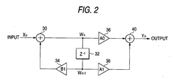
- the integration processing based on the digital filter is the operation processing containing at least an integration element which is carried out to determine from the angular velocity signal the position (target position) of the antivibration lens for correcting the image blur detected on the basis of the angular velocity signal.
- the angle signal achieved through the integration processing in the digital filter does not represent an accurate integration value of the angular velocity signal, it may be also called as an angle signal.
- the angle signal concerned indicates the value of the position (target position) of the antivibration lens for correcting the image blur detected on the basis of the angular velocity signal.
- the digital filter for carrying out digital integration has such a characteristic that when the frequency is low, the phase delay of the output signal of the digital filter approaches to 90 degrees as the frequency is increased as in the case of the related art and also the phase delay is gradually reduced as the frequency is increased when the frequency is equal to a certain frequency or more. Therefore, the phase delay caused by the processing times of the filter operation, etc. canbe reduced. It is general in the related art that the multiplication constants A0 and A1 of the digital filter are set to the same value and also set to a value near to zero.
- the angular velocity signal output from the angular velocity sensor 10 is amplified by an amplifying circuit 12, DC components are removed therefrom by a high pass filter 14, and high frequency noises are removed by a low pass filter 16. Subsequently, the analog angular velocity signal is converted to a digital signal by an A/D converter 18, and then sampled at a predetermined sampling period by a digital filter 20.
- Figs. 3A and 3B show filter characteristics based on the multiplication constants of this embodiment
- Figs. 4A and 4B show filter characteristics of the multiplication constants of the related art
- Figs. 3A, 3B, 4A and 4B show the filter characteristics to the frequency area (several Hz to several tens Hz) of vibration (angular velocity signal) to be subjected to the image blur correction
- Fig. 3A and Fig. 4A show gain characteristics
- Figs. 3B and Fig. 4B show phase characteristics.
Landscapes
- Engineering & Computer Science (AREA)
- Multimedia (AREA)
- Signal Processing (AREA)
- Physics & Mathematics (AREA)
- General Physics & Mathematics (AREA)
- Adjustment Of Camera Lenses (AREA)
- Studio Devices (AREA)
Abstract
Description
Claims (3)
- An image blur correcting device comprising: a vibration detecting unit that detects a vibration signal indicating a vibration of an optical system for focusing an image; and a digital filter that digitally integrates the vibration signal to generate an output signal, so as to correct an image blur based on the output signal,
wherein the digital filter performs(i) calculating an addition value Wn based on: Wn = Xn + B1 × Wn-1 (n=1,2,3···),
in which Xn is an input value input by sampling the vibration signal every a sampling period, B1 is a first multiplication constant, and Wn-1 is a first delay value calculated when an input value Xn-1 was previously input by one sampling,(ii) storing the addition value Wn as a delay value,(iii) calculating an addition value Yn based on: Yn = A0 × Wn + A1 × Wn-1 (n=1,2,3···),
in which A0 is a second multiplication constant which satisfies 0 < A0 < 1 and is near to 1, and A1 is a third multiplication constant which satisfies 0 < A1 < 1 and is near to 0, and(iv) outputting the addition value Yn as an output value Yn corresponding to the output signal. - The image blur correcting device according to claim 1, wherein the first multiplication constant B1 satisfies 0 < B1 < 1 and near to 1.
- The image blur correcting device according to claim 1, wherein the vibration detecting unit comprises an angular velocity sensor that detects an angular velocity of the vibration of the optical system, and the vibration signal is an angular velocity signal.
Applications Claiming Priority (2)
| Application Number | Priority Date | Filing Date | Title |
|---|---|---|---|
| JP2004067751A JP2005257919A (en) | 2004-03-10 | 2004-03-10 | Image blurring correction device |
| JP2004067751 | 2004-03-10 |
Publications (2)
| Publication Number | Publication Date |
|---|---|
| EP1575279A2 true EP1575279A2 (en) | 2005-09-14 |
| EP1575279A3 EP1575279A3 (en) | 2006-08-02 |
Family
ID=34824586
Family Applications (1)
| Application Number | Title | Priority Date | Filing Date |
|---|---|---|---|
| EP05004586A Withdrawn EP1575279A3 (en) | 2004-03-10 | 2005-03-02 | Image blur correcting device |
Country Status (3)
| Country | Link |
|---|---|
| US (1) | US20050201741A1 (en) |
| EP (1) | EP1575279A3 (en) |
| JP (1) | JP2005257919A (en) |
Families Citing this family (11)
| Publication number | Priority date | Publication date | Assignee | Title |
|---|---|---|---|---|
| US7424212B2 (en) * | 2004-11-12 | 2008-09-09 | Fujifilm Corporation | Camera shaking correcting method, camera shaking correcting device, and image pickup device |
| JP4760175B2 (en) * | 2005-07-12 | 2011-08-31 | 富士フイルム株式会社 | Image blur correction device |
| JP4817976B2 (en) * | 2006-06-08 | 2011-11-16 | キヤノン株式会社 | Drive control device, drive control method, and program |
| JP5237622B2 (en) * | 2007-12-21 | 2013-07-17 | セミコンダクター・コンポーネンツ・インダストリーズ・リミテッド・ライアビリティ・カンパニー | Vibration correction control circuit and imaging apparatus including the same |
| JP5242151B2 (en) * | 2007-12-21 | 2013-07-24 | セミコンダクター・コンポーネンツ・インダストリーズ・リミテッド・ライアビリティ・カンパニー | Vibration correction control circuit and imaging apparatus including the same |
| JP2009156946A (en) * | 2007-12-25 | 2009-07-16 | Sanyo Electric Co Ltd | Anti-vibration control circuit for imaging device |
| JP5147384B2 (en) * | 2007-12-25 | 2013-02-20 | オンセミコンダクター・トレーディング・リミテッド | Vibration compensation control circuit |
| JP5348881B2 (en) * | 2007-12-25 | 2013-11-20 | セミコンダクター・コンポーネンツ・インダストリーズ・リミテッド・ライアビリティ・カンパニー | Vibration compensation control circuit |
| JP5298269B2 (en) * | 2007-12-25 | 2013-09-25 | セミコンダクター・コンポーネンツ・インダストリーズ・リミテッド・ライアビリティ・カンパニー | Vibration compensation control circuit |
| JP2009156945A (en) | 2007-12-25 | 2009-07-16 | Sanyo Electric Co Ltd | Anti-vibration control circuit for imaging device |
| JP5302094B2 (en) * | 2009-05-12 | 2013-10-02 | 富士フイルム株式会社 | Image blur correction device |
Family Cites Families (3)
| Publication number | Priority date | Publication date | Assignee | Title |
|---|---|---|---|---|
| US5734932A (en) * | 1991-05-31 | 1998-03-31 | Canon Kabushiki Kaisha | Image stabilizing device for camera |
| US5873004A (en) * | 1991-09-06 | 1999-02-16 | Canon Kabushiki Kaisha | Image stabilizing apparatus |
| US6233009B1 (en) * | 1993-09-08 | 2001-05-15 | Canon Kabushiki Kaisha | Image-shake correcting device for detecting vibration frequency and for changing vibration characteristics |
-
2004
- 2004-03-10 JP JP2004067751A patent/JP2005257919A/en not_active Withdrawn
-
2005
- 2005-03-02 EP EP05004586A patent/EP1575279A3/en not_active Withdrawn
- 2005-03-08 US US11/073,538 patent/US20050201741A1/en not_active Abandoned
Also Published As
| Publication number | Publication date |
|---|---|
| JP2005257919A (en) | 2005-09-22 |
| US20050201741A1 (en) | 2005-09-15 |
| EP1575279A3 (en) | 2006-08-02 |
Similar Documents
| Publication | Publication Date | Title |
|---|---|---|
| US8629910B2 (en) | Image capture apparatus and control method thereof | |
| JP6362556B2 (en) | Control device, imaging device, control method, program, and storage medium | |
| US7856179B2 (en) | Image stabilization control circuit and image-capturing device | |
| KR100990265B1 (en) | Dustproof Control Circuit of Imaging Device | |
| US9277102B2 (en) | Audio processing apparatus, audio processing method and imaging apparatus | |
| JP2007189478A (en) | Vibration correction apparatus and optical apparatus | |
| US20050201741A1 (en) | Image blur correcting device | |
| US20150198818A1 (en) | Image shake correcting apparatus and its control method | |
| US8923691B2 (en) | Shake correcting device and imaging apparatus having shake correcting device | |
| EP0455445A2 (en) | Image pick-up apparatus | |
| JP5247782B2 (en) | Optical apparatus, imaging apparatus including the same, and control method of optical apparatus | |
| JP4536855B2 (en) | Anti-vibration device, imaging device, and control method of anti-vibration device | |
| JPH08307762A (en) | Shake correction device | |
| KR101608828B1 (en) | Apparatus for vibration compensation of gyro sensor of mobile camera | |
| KR101587972B1 (en) | Image sensor module for vibration compensation | |
| KR101569823B1 (en) | Gyro sensor module for vibration compensation | |
| JP4776974B2 (en) | Image blur correcting lens device and correction method thereof | |
| JP3865125B2 (en) | Image processing apparatus and method, recording medium, and program | |
| JP4760175B2 (en) | Image blur correction device | |
| JP2009217075A (en) | Imaging apparatus | |
| JP2009156945A (en) | Anti-vibration control circuit for imaging device | |
| JPH08313950A (en) | Image stabilizer | |
| JP2011170383A (en) | Lens device and imaging apparatus including the same | |
| JP2006011252A (en) | Image stabilizer system | |
| JP2014041230A (en) | Optical device having image blur correction function and control method of the same |
Legal Events
| Date | Code | Title | Description |
|---|---|---|---|
| PUAI | Public reference made under article 153(3) epc to a published international application that has entered the european phase |
Free format text: ORIGINAL CODE: 0009012 |
|
| AK | Designated contracting states |
Kind code of ref document: A2 Designated state(s): AT BE BG CH CY CZ DE DK EE ES FI FR GB GR HU IE IS IT LI LT LU MC NL PL PT RO SE SI SK TR |
|
| AX | Request for extension of the european patent |
Extension state: AL BA HR LV MK YU |
|
| PUAL | Search report despatched |
Free format text: ORIGINAL CODE: 0009013 |
|
| AK | Designated contracting states |
Kind code of ref document: A3 Designated state(s): AT BE BG CH CY CZ DE DK EE ES FI FR GB GR HU IE IS IT LI LT LU MC NL PL PT RO SE SI SK TR |
|
| AX | Request for extension of the european patent |
Extension state: AL BA HR LV MK YU |
|
| AKX | Designation fees paid | ||
| STAA | Information on the status of an ep patent application or granted ep patent |
Free format text: STATUS: THE APPLICATION IS DEEMED TO BE WITHDRAWN |
|
| 18D | Application deemed to be withdrawn |
Effective date: 20070203 |
|
| REG | Reference to a national code |
Ref country code: DE Ref legal event code: 8566 |