EP1575276A1 - Camcorder - Google Patents
Camcorder Download PDFInfo
- Publication number
- EP1575276A1 EP1575276A1 EP05101750A EP05101750A EP1575276A1 EP 1575276 A1 EP1575276 A1 EP 1575276A1 EP 05101750 A EP05101750 A EP 05101750A EP 05101750 A EP05101750 A EP 05101750A EP 1575276 A1 EP1575276 A1 EP 1575276A1
- Authority
- EP
- European Patent Office
- Prior art keywords
- deck
- door
- camcorder
- tape
- photographing apparatus
- Prior art date
- Legal status (The legal status is an assumption and is not a legal conclusion. Google has not performed a legal analysis and makes no representation as to the accuracy of the status listed.)
- Withdrawn
Links
Images

Classifications
-
- B—PERFORMING OPERATIONS; TRANSPORTING
- B01—PHYSICAL OR CHEMICAL PROCESSES OR APPARATUS IN GENERAL
- B01D—SEPARATION
- B01D46/00—Filters or filtering processes specially modified for separating dispersed particles from gases or vapours
- B01D46/42—Auxiliary equipment or operation thereof
- B01D46/44—Auxiliary equipment or operation thereof controlling filtration
-
- G—PHYSICS
- G03—PHOTOGRAPHY; CINEMATOGRAPHY; ANALOGOUS TECHNIQUES USING WAVES OTHER THAN OPTICAL WAVES; ELECTROGRAPHY; HOLOGRAPHY
- G03B—APPARATUS OR ARRANGEMENTS FOR TAKING PHOTOGRAPHS OR FOR PROJECTING OR VIEWING THEM; APPARATUS OR ARRANGEMENTS EMPLOYING ANALOGOUS TECHNIQUES USING WAVES OTHER THAN OPTICAL WAVES; ACCESSORIES THEREFOR
- G03B17/00—Details of cameras or camera bodies; Accessories therefor
- G03B17/02—Bodies
-
- B—PERFORMING OPERATIONS; TRANSPORTING
- B01—PHYSICAL OR CHEMICAL PROCESSES OR APPARATUS IN GENERAL
- B01D—SEPARATION
- B01D39/00—Filtering material for liquid or gaseous fluids
- B01D39/14—Other self-supporting filtering material ; Other filtering material
- B01D39/20—Other self-supporting filtering material ; Other filtering material of inorganic material, e.g. asbestos paper, metallic filtering material of non-woven wires
- B01D39/2055—Carbonaceous material
-
- B—PERFORMING OPERATIONS; TRANSPORTING
- B01—PHYSICAL OR CHEMICAL PROCESSES OR APPARATUS IN GENERAL
- B01D—SEPARATION
- B01D46/00—Filters or filtering processes specially modified for separating dispersed particles from gases or vapours
- B01D46/0027—Filters or filtering processes specially modified for separating dispersed particles from gases or vapours with additional separating or treating functions
- B01D46/0028—Filters or filtering processes specially modified for separating dispersed particles from gases or vapours with additional separating or treating functions provided with antibacterial or antifungal means
-
- B—PERFORMING OPERATIONS; TRANSPORTING
- B01—PHYSICAL OR CHEMICAL PROCESSES OR APPARATUS IN GENERAL
- B01D—SEPARATION
- B01D46/00—Filters or filtering processes specially modified for separating dispersed particles from gases or vapours
- B01D46/0027—Filters or filtering processes specially modified for separating dispersed particles from gases or vapours with additional separating or treating functions
- B01D46/0032—Filters or filtering processes specially modified for separating dispersed particles from gases or vapours with additional separating or treating functions using electrostatic forces to remove particles, e.g. electret filters
-
- B—PERFORMING OPERATIONS; TRANSPORTING
- B01—PHYSICAL OR CHEMICAL PROCESSES OR APPARATUS IN GENERAL
- B01D—SEPARATION
- B01D46/00—Filters or filtering processes specially modified for separating dispersed particles from gases or vapours
- B01D46/0039—Filters or filtering processes specially modified for separating dispersed particles from gases or vapours with flow guiding by feed or discharge devices
-
- B—PERFORMING OPERATIONS; TRANSPORTING
- B01—PHYSICAL OR CHEMICAL PROCESSES OR APPARATUS IN GENERAL
- B01D—SEPARATION
- B01D46/00—Filters or filtering processes specially modified for separating dispersed particles from gases or vapours
- B01D46/10—Particle separators, e.g. dust precipitators, using filter plates, sheets or pads having plane surfaces
- B01D46/12—Particle separators, e.g. dust precipitators, using filter plates, sheets or pads having plane surfaces in multiple arrangements
-
- B—PERFORMING OPERATIONS; TRANSPORTING
- B01—PHYSICAL OR CHEMICAL PROCESSES OR APPARATUS IN GENERAL
- B01J—CHEMICAL OR PHYSICAL PROCESSES, e.g. CATALYSIS OR COLLOID CHEMISTRY; THEIR RELEVANT APPARATUS
- B01J20/00—Solid sorbent compositions or filter aid compositions; Sorbents for chromatography; Processes for preparing, regenerating or reactivating thereof
- B01J20/02—Solid sorbent compositions or filter aid compositions; Sorbents for chromatography; Processes for preparing, regenerating or reactivating thereof comprising inorganic material
- B01J20/20—Solid sorbent compositions or filter aid compositions; Sorbents for chromatography; Processes for preparing, regenerating or reactivating thereof comprising inorganic material comprising free carbon; comprising carbon obtained by carbonising processes
-
- B—PERFORMING OPERATIONS; TRANSPORTING
- B82—NANOTECHNOLOGY
- B82Y—SPECIFIC USES OR APPLICATIONS OF NANOSTRUCTURES; MEASUREMENT OR ANALYSIS OF NANOSTRUCTURES; MANUFACTURE OR TREATMENT OF NANOSTRUCTURES
- B82Y30/00—Nanotechnology for materials or surface science, e.g. nanocomposites
-
- F—MECHANICAL ENGINEERING; LIGHTING; HEATING; WEAPONS; BLASTING
- F16—ENGINEERING ELEMENTS AND UNITS; GENERAL MEASURES FOR PRODUCING AND MAINTAINING EFFECTIVE FUNCTIONING OF MACHINES OR INSTALLATIONS; THERMAL INSULATION IN GENERAL
- F16L—PIPES; JOINTS OR FITTINGS FOR PIPES; SUPPORTS FOR PIPES, CABLES OR PROTECTIVE TUBING; MEANS FOR THERMAL INSULATION IN GENERAL
- F16L11/00—Hoses, i.e. flexible pipes
-
- H—ELECTRICITY
- H04—ELECTRIC COMMUNICATION TECHNIQUE
- H04N—PICTORIAL COMMUNICATION, e.g. TELEVISION
- H04N23/00—Cameras or camera modules comprising electronic image sensors; Control thereof
- H04N23/50—Constructional details
- H04N23/51—Housings
-
- B—PERFORMING OPERATIONS; TRANSPORTING
- B01—PHYSICAL OR CHEMICAL PROCESSES OR APPARATUS IN GENERAL
- B01D—SEPARATION
- B01D2259/00—Type of treatment
- B01D2259/45—Gas separation or purification devices adapted for specific applications
- B01D2259/455—Gas separation or purification devices adapted for specific applications for transportable use
Definitions
- the present invention relates to a camcorder comprising a tape deck and a tape deck door.
- Portable imaging apparatuses have become widely used, mainly due to their convenience.
- Portable imaging apparatuses are used in a variety of circumstances, including hobby and leisure activities. Thanks to advancements in digital technology, digital cameras and camcorders are now rapidly replacing analogue ones.
- a camcorder combines the functions of a tape recorder and a camera.
- Camcorders are able to record, reproduce and edit image information, as desired by the operator.
- Camcorder can be divided into two categories, hand held types and shoulder types.
- the shoulder-type camcorders are expensive and are generally for professional use.
- the hand held-type camcorders are compact and light-weight, and are wide spread, especially for personal use.
- Hand held camcorders can also be divided into two categories, shooting and vertical, according to their shapes. Shooting-type camcorders resemble guns in that the length is greater than the height. In contrast, vertical-type camcorders are taller than they are long.
- a deck unit (not shown) is mounted inside an outer casing of the camcorder body 120, in which a camera unit 110 is integrally formed.
- the exterior structure is arranged such that a housing door 140 can be opened and closed, irrespective of the type of the model, in a vertical direction about a horizontal axis for the loading and unloading tape cassettes (not shown) into/out of the deck unit (not shown).
- a camcorder is characterised in that the tape deck door is hinged so a to swing forwards for opening, enabling a tape cassette to be inserted from behind.
- the term "front” should be taken to mean that part of the camcorder that is directed towards a subject being captured. Thus, an objective lens is to be found at a front position and an eyepiece will often be found at a rear position.
- the axis of rotation of the tape deck door for opening is substantially perpendicular to the main, front to rear axis of the camcorder.
- the tape deck includes a head drum towards one side and the tape deck is positioned such that the head drum side of the tape deck is towards the front of the camcorder.
- an camcorder 200 comprises a body 220, having a deck unit 230 for a recording medium, such as a magnetic tape, for the recording and reproduction of image information of an object captured by a camera unit 210, having a PCB (printed circuit board) mounted therein.
- a housing door 240 movably engaged to one side of the body 220 to hinge open and closed for loading and unloading of a tape cassette (C).
- the housing door 240 is opens towards the front of the body 220.
- the tape cassette (C) is loaded towards the ocular lens 212 end of the body from objective lens 211 end of the body.
- the tape cassette (C) is ejected toward the end of the body 220 having the objective lens 211 from the ocular lens 212 end of the body.
- the deck unit 230 although not illustrated in drawings in detail, is mounted in a substantially vertical direction so that a head drum is located near the ocular lens 212.
- the head drum is arranged to face an upper or lower portion of the deck unit 230.
- the hingedly connected housing door 240 rotates between open and closed positions about a vertical axis.
- the deck unit 230 generally has a horizontal arrangement.
- the deck unit 230 is formed approximately at 90° left or right from the horizontal axis of of the product.
- a tape cassette arranged in a vertical relation with respect to the body 220, is loaded and unloaded through the front of the deck unit 230 through the housing door 240.
- the housing door 240 comprises a housing frame 241, preferably formed of metal frames by moulding.
- the housing door 240 engages with the deck unit 230 for hingedly rotating.
- the housing frame 241 comprises a pair of links 241 a, 241b.
- the pair of links 241 a, 241b engage a pair of hinge frames 231, 232 protruding from opposite sides of the deck unit 230, forming a hinge structure (h).
- the reference character G denotes a guide slot for restricting the hinge movement of the housing frame 241 and the door frame 242, and the reference character P denotes a guide pin engaged in the guide slot (G).
- a window 244 is also provided.
- the improved structure for opening and closing a housing door with respect to the deck unit allows a cassette of image recording medium to be loaded and unloaded with respect to the deck unit from the front to the rear side of the camcorder, at a substantially orthogonal position with respect to a plane of the deck unit. Consequently, the size of the exterior structure, especially the lateral length of the image photographing apparatus can be reduced, and a compact image photographing apparatus is provided, which is convenient to use and adjust.
Landscapes
- Chemical & Material Sciences (AREA)
- Chemical Kinetics & Catalysis (AREA)
- Engineering & Computer Science (AREA)
- General Physics & Mathematics (AREA)
- Physics & Mathematics (AREA)
- Signal Processing (AREA)
- Multimedia (AREA)
- General Engineering & Computer Science (AREA)
- Nanotechnology (AREA)
- Materials Engineering (AREA)
- Condensed Matter Physics & Semiconductors (AREA)
- Crystallography & Structural Chemistry (AREA)
- Composite Materials (AREA)
- Organic Chemistry (AREA)
- Mechanical Engineering (AREA)
- Life Sciences & Earth Sciences (AREA)
- Geology (AREA)
- Analytical Chemistry (AREA)
- Inorganic Chemistry (AREA)
- Studio Devices (AREA)
Abstract
An image photographing apparatus such as a camcorder has an improved structure
for opening and closing a housing door of a deck unit. A tape cassette is mounted
to the deck unit from the front to the rear side of the apparatus, and substantially
vertically with respect to the deck unit. Accordingly, compact-sized image
photographing apparatus can be provided.
Description
- The present invention relates to a camcorder comprising a tape deck and a tape deck door.
- Recently, portable imaging apparatuses have become widely used, mainly due to their convenience. Portable imaging apparatuses are used in a variety of circumstances, including hobby and leisure activities. Thanks to advancements in digital technology, digital cameras and camcorders are now rapidly replacing analogue ones.
- Generally, a camcorder combines the functions of a tape recorder and a camera. Camcorders are able to record, reproduce and edit image information, as desired by the operator. Camcorder can be divided into two categories, hand held types and shoulder types. The shoulder-type camcorders are expensive and are generally for professional use. The hand held-type camcorders are compact and light-weight, and are wide spread, especially for personal use.
- Hand held camcorders can also be divided into two categories, shooting and vertical, according to their shapes. Shooting-type camcorders resemble guns in that the length is greater than the height. In contrast, vertical-type camcorders are taller than they are long.
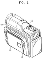
- In a typical conventional hand-held camcorder, a deck unit (not shown) is mounted inside an outer casing of the
camcorder body 120, in which acamera unit 110 is integrally formed. The exterior structure is arranged such that ahousing door 140 can be opened and closed, irrespective of the type of the model, in a vertical direction about a horizontal axis for the loading and unloading tape cassettes (not shown) into/out of the deck unit (not shown). - Accordingly, a variety of associated equipment structures are required for the realization of the opening and closing structure of the housing door mentioned above, and, therefore, space, especially in a lateral direction, is necessary. As a result, realization of compact products in the future is limited. Moreover, another drawaback is that when the housing door is opened and closed in the downward direction, the cassette tape may tilt downward during the operation of the product, and therefore, stability is affected.
- A camcorder, according to the present invention, is characterised in that the tape deck door is hinged so a to swing forwards for opening, enabling a tape cassette to be inserted from behind. The term "front" should be taken to mean that part of the camcorder that is directed towards a subject being captured. Thus, an objective lens is to be found at a front position and an eyepiece will often be found at a rear position.
- Preferably, the axis of rotation of the tape deck door for opening is substantially perpendicular to the main, front to rear axis of the camcorder.
- Preferably, the tape deck includes a head drum towards one side and the tape deck is positioned such that the head drum side of the tape deck is towards the front of the camcorder.
- An embodiment of the present invention will now be described, by way of example, with reference to the accompanying drawings, in which:
- Figure 1 is a perspective view of a typical conventional camcorder;
- Figure 2 is a plan view illustrating the outer structure of a camcorder according to the present invention; and
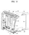
- Figure 3 is a perspective view of a housing door of the camcorder of Figure 2.
-
- The description of well-known functions will be omitted for conciseness. Referring to Figure 2, an
camcorder 200, according to the present invention, comprises abody 220, having adeck unit 230 for a recording medium, such as a magnetic tape, for the recording and reproduction of image information of an object captured by acamera unit 210, having a PCB (printed circuit board) mounted therein. Ahousing door 240 movably engaged to one side of thebody 220 to hinge open and closed for loading and unloading of a tape cassette (C). - In the
camcorder 200 as described above, thehousing door 240 is opens towards the front of thebody 220. The tape cassette (C) is loaded towards theocular lens 212 end of the body fromobjective lens 211 end of the body. The tape cassette (C) is ejected toward the end of thebody 220 having theobjective lens 211 from theocular lens 212 end of the body. - The
deck unit 230, although not illustrated in drawings in detail, is mounted in a substantially vertical direction so that a head drum is located near theocular lens 212. For example, the head drum is arranged to face an upper or lower portion of thedeck unit 230. The hingedly connectedhousing door 240 rotates between open and closed positions about a vertical axis. In such ageneral camcorder 200, thedeck unit 230 generally has a horizontal arrangement. However, in the present embodiment, thedeck unit 230 is formed approximately at 90° left or right from the horizontal axis of of the product. - Accordingly, a tape cassette, arranged in a vertical relation with respect to the
body 220, is loaded and unloaded through the front of thedeck unit 230 through thehousing door 240. - Referring to Figure 3, the
housing door 240 comprises ahousing frame 241, preferably formed of metal frames by moulding. Thehousing door 240 engages with thedeck unit 230 for hingedly rotating. Adoor frame 242, preferably formed by injection molding, is joined to thehousing frame 241 by a plurality of screws (S) covering thehousing frame 241, thus forming a part of the exterior of the outer casing of thebody 220. - The
housing frame 241 comprises a pair oflinks links hinge frames deck unit 230, forming a hinge structure (h). The reference character G denotes a guide slot for restricting the hinge movement of thehousing frame 241 and thedoor frame 242, and the reference character P denotes a guide pin engaged in the guide slot (G). Awindow 244 is also provided. - With the camcorder forward-opening housing door structure described above, a tape cassette is loaded and unloaded with respect to the
deck unit 230 through the forwardly openable housing door, along a plane substantially orthogonal with respect to thedeck unit 230. As a result, the overall lateral length of the product is reduced and a compact camcorder having a unique exterior structure is provided. - As described above, the improved structure for opening and closing a housing door with respect to the deck unit allows a cassette of image recording medium to be loaded and unloaded with respect to the deck unit from the front to the rear side of the camcorder, at a substantially orthogonal position with respect to a plane of the deck unit. Consequently, the size of the exterior structure, especially the lateral length of the image photographing apparatus can be reduced, and a compact image photographing apparatus is provided, which is convenient to use and adjust.
Claims (11)
- A camcorder comprising a tape deck and a tape deck door (240), characterised in that the tape deck door (240) is hinged so a to swing forwards for opening, enabling a tape cassette (C) to be inserted from behind.
- A camcorder according to claim 1, including an objective lens (211) at a front position and an eyepiece (212) at a rear position.
- A camcorder according to claim 1 or 2, wherein the axis of rotation of the tape deck door (240) for opening is substantially perpendicular to the main, front to rear axis of the camcorder.
- A camcorder according to claim 1, 2 or 3, wherein the tape deck includes a head drum towards one side and the tape deck is positioned such that the head drum side of the tape deck is towards the front of the camcorder.
- An image photographing apparatus, comprising:a body having a deck unit for recording/reproducing of image information inputted through a camera unit, and a printed circuit board mounted therein; the body being configured to have an ocular lens mounted on one end thereof, and an objective lens mounted on the other end thereof, anda housing door movably mounted on a side of the body to allow loading and unloading of a tape cassette with respect to the deck unit, wherein the housing door is hingedly opened and closed proximate the front side of the body,the tape cassette is loaded from the objective lens end toward an ocular lens end of the body, and upon being mounted in the deck unit, the tape cassette is ejected from the ocular lens end toward the objective lens end of the body.
- The image photographing apparatus of claim 5, wherein the tape cassette is forwardly loaded in the deck unit, and substantially vertically with respect to the body.
- The image photographing apparatus of claim 5, wherein the deck is unit is oriented substantially vertical so that a head drum is located near the ocular lens end of the camera unit.
- The image photographing apparatus of claim 5, wherein
the housing door further comprises a plurality of links for engaging a plurality of apertures disposed on a hinge frame of the deck unit for connecting the housing door to the deck unit. - The image photographing apparatus of claim 8, wherein
the housing door further comprises a door frame and a housing frame. - The image photographing apparatus of claim 8, wherein
the housing door has a guide opening , and a guide pin engageable with the guide opening for limiting movement of the housing frame. - The image photographing apparatus of claim 8, wherein
the housing door has a guide opening, and a guide pin egangeable with the guide opening for limiting movement of the door frame.
Applications Claiming Priority (2)
| Application Number | Priority Date | Filing Date | Title |
|---|---|---|---|
| KR1020040016085A KR20050090820A (en) | 2004-03-10 | 2004-03-10 | Image photographing appratus |
| KR2004016085 | 2004-03-10 |
Publications (1)
| Publication Number | Publication Date |
|---|---|
| EP1575276A1 true EP1575276A1 (en) | 2005-09-14 |
Family
ID=34825206
Family Applications (1)
| Application Number | Title | Priority Date | Filing Date |
|---|---|---|---|
| EP05101750A Withdrawn EP1575276A1 (en) | 2004-03-10 | 2005-03-07 | Camcorder |
Country Status (5)
| Country | Link |
|---|---|
| US (1) | US20050200756A1 (en) |
| EP (1) | EP1575276A1 (en) |
| JP (1) | JP2005260957A (en) |
| KR (1) | KR20050090820A (en) |
| CN (1) | CN1667491A (en) |
Families Citing this family (4)
| Publication number | Priority date | Publication date | Assignee | Title |
|---|---|---|---|---|
| KR20050090821A (en) * | 2004-03-10 | 2005-09-14 | 삼성전자주식회사 | Housing cover for image photographing appratus |
| CN101346986A (en) * | 2005-12-26 | 2009-01-14 | 松下电器产业株式会社 | Imaging device |
| JP1571316S (en) | 2016-05-17 | 2017-03-13 | ||
| JP1571919S (en) * | 2016-05-17 | 2017-03-21 |
Citations (6)
| Publication number | Priority date | Publication date | Assignee | Title |
|---|---|---|---|---|
| JPH02276374A (en) * | 1989-04-18 | 1990-11-13 | Hitachi Ltd | Vcr incorporated type camera |
| JPH07143428A (en) * | 1993-11-16 | 1995-06-02 | Canon Inc | Magnetic recording / reproducing device |
| JPH0934003A (en) * | 1995-07-14 | 1997-02-07 | Minolta Co Ltd | Camera using film pack |
| US5960156A (en) * | 1991-09-04 | 1999-09-28 | Hitachi, Ltd. | Video camera combined with recording and reproducing system having a camera unit, a viewfinder unit, and a battery unit arranged in a projection area of a recording and reproducing deck unit |
| JP2001053994A (en) * | 1999-08-10 | 2001-02-23 | Sony Corp | Video camera |
| WO2001026364A1 (en) * | 1999-10-04 | 2001-04-12 | Hitachi, Ltd. | Camcorder with optical disk |
Family Cites Families (5)
| Publication number | Priority date | Publication date | Assignee | Title |
|---|---|---|---|---|
| US5657083A (en) * | 1991-09-05 | 1997-08-12 | Canon Kabushiki Kaisha | Video camera having parts arranged to reduce affects of shake |
| CA2130011C (en) * | 1993-08-24 | 2004-03-30 | Masayoshi Morikawa | Cassette eject mechanism, battery loading mechanism and mechanical chassis supporting mechanism |
| JP3726272B2 (en) * | 1996-08-21 | 2005-12-14 | 富士写真フイルム株式会社 | Digital camera |
| US20050147397A1 (en) * | 2003-12-17 | 2005-07-07 | Sony Corporation | Image pickup apparatus |
| KR20050090821A (en) * | 2004-03-10 | 2005-09-14 | 삼성전자주식회사 | Housing cover for image photographing appratus |
-
2004
- 2004-03-10 KR KR1020040016085A patent/KR20050090820A/en not_active Withdrawn
-
2005
- 2005-02-17 US US11/059,562 patent/US20050200756A1/en not_active Abandoned
- 2005-03-07 CN CNA2005100513056A patent/CN1667491A/en active Pending
- 2005-03-07 EP EP05101750A patent/EP1575276A1/en not_active Withdrawn
- 2005-03-09 JP JP2005066162A patent/JP2005260957A/en active Pending
Patent Citations (6)
| Publication number | Priority date | Publication date | Assignee | Title |
|---|---|---|---|---|
| JPH02276374A (en) * | 1989-04-18 | 1990-11-13 | Hitachi Ltd | Vcr incorporated type camera |
| US5960156A (en) * | 1991-09-04 | 1999-09-28 | Hitachi, Ltd. | Video camera combined with recording and reproducing system having a camera unit, a viewfinder unit, and a battery unit arranged in a projection area of a recording and reproducing deck unit |
| JPH07143428A (en) * | 1993-11-16 | 1995-06-02 | Canon Inc | Magnetic recording / reproducing device |
| JPH0934003A (en) * | 1995-07-14 | 1997-02-07 | Minolta Co Ltd | Camera using film pack |
| JP2001053994A (en) * | 1999-08-10 | 2001-02-23 | Sony Corp | Video camera |
| WO2001026364A1 (en) * | 1999-10-04 | 2001-04-12 | Hitachi, Ltd. | Camcorder with optical disk |
Non-Patent Citations (3)
| Title |
|---|
| PATENT ABSTRACTS OF JAPAN vol. 015, no. 040 (E - 1028) 30 January 1991 (1991-01-30) * |
| PATENT ABSTRACTS OF JAPAN vol. 1995, no. 09 31 October 1995 (1995-10-31) * |
| PATENT ABSTRACTS OF JAPAN vol. 2000, no. 19 5 June 2001 (2001-06-05) * |
Also Published As
| Publication number | Publication date |
|---|---|
| US20050200756A1 (en) | 2005-09-15 |
| CN1667491A (en) | 2005-09-14 |
| KR20050090820A (en) | 2005-09-14 |
| JP2005260957A (en) | 2005-09-22 |
Similar Documents
| Publication | Publication Date | Title |
|---|---|---|
| CA2130011C (en) | Cassette eject mechanism, battery loading mechanism and mechanical chassis supporting mechanism | |
| US7405751B2 (en) | Image photographing apparatus having photographic mode based on position of camera unit | |
| US5515174A (en) | Camera-integrated video recorder apparatus having a concealable operation member | |
| EP1575276A1 (en) | Camcorder | |
| KR100622850B1 (en) | Recording and reproducing device integrated with camera | |
| US7385647B2 (en) | Housing cover for image photographing apparatus | |
| EP1575273A1 (en) | Duocam and method of assembly thereof | |
| US5523907A (en) | Door mechanism for a tape recorder | |
| US5526210A (en) | Tape cassette for loading by a cassette inserting and ejecting apparatus | |
| JP2009065397A (en) | Shoe adapter and imaging device | |
| JP3640283B2 (en) | Magnetic tape cassette | |
| JPS62266986A (en) | Portable electronic camera | |
| JP4248384B2 (en) | Imaging device provided with card-type recording medium attaching / detaching device | |
| JP4300640B2 (en) | Imaging device | |
| JP4228478B2 (en) | Imaging device | |
| CN100477736C (en) | Electronic apparatus and image capturing apparatus | |
| KR20050075893A (en) | Image photographing apparatus | |
| EP1575052A2 (en) | Tape deck | |
| JPH06295556A (en) | Tape cassette | |
| JP2004135338A (en) | Video camera | |
| JP3470238B2 (en) | Tape cartridge | |
| JPH05314713A (en) | Tape cartridge | |
| JPH0537832A (en) | Imaging recording / playback device | |
| JP2000270246A (en) | Video camera | |
| JP2006073477A (en) | Click mechanism of slide switch and click mechanism of slide switch for imaging device |
Legal Events
| Date | Code | Title | Description |
|---|---|---|---|
| PUAI | Public reference made under article 153(3) epc to a published international application that has entered the european phase |
Free format text: ORIGINAL CODE: 0009012 |
|
| AK | Designated contracting states |
Kind code of ref document: A1 Designated state(s): AT BE BG CH CY CZ DE DK EE ES FI FR GB GR HU IE IS IT LI LT LU MC NL PL PT RO SE SI SK TR |
|
| AX | Request for extension of the european patent |
Extension state: AL BA HR LV MK YU |
|
| 17P | Request for examination filed |
Effective date: 20051024 |
|
| AKX | Designation fees paid |
Designated state(s): DE GB NL |
|
| STAA | Information on the status of an ep patent application or granted ep patent |
Free format text: STATUS: THE APPLICATION IS DEEMED TO BE WITHDRAWN |
|
| 18D | Application deemed to be withdrawn |
Effective date: 20070920 |