EP1575271A1 - A camera apparatus having a flash - Google Patents
A camera apparatus having a flash Download PDFInfo
- Publication number
- EP1575271A1 EP1575271A1 EP05101477A EP05101477A EP1575271A1 EP 1575271 A1 EP1575271 A1 EP 1575271A1 EP 05101477 A EP05101477 A EP 05101477A EP 05101477 A EP05101477 A EP 05101477A EP 1575271 A1 EP1575271 A1 EP 1575271A1
- Authority
- EP
- European Patent Office
- Prior art keywords
- image photographing
- image
- photographing device
- main body
- device unit
- Prior art date
- Legal status (The legal status is an assumption and is not a legal conclusion. Google has not performed a legal analysis and makes no representation as to the accuracy of the status listed.)
- Withdrawn
Links
Images


Classifications
-
- H—ELECTRICITY
- H04—ELECTRIC COMMUNICATION TECHNIQUE
- H04N—PICTORIAL COMMUNICATION, e.g. TELEVISION
- H04N1/00—Scanning, transmission or reproduction of documents or the like, e.g. facsimile transmission; Details thereof
- H04N1/21—Intermediate information storage
- H04N1/2104—Intermediate information storage for one or a few pictures
- H04N1/2112—Intermediate information storage for one or a few pictures using still video cameras
- H04N1/212—Motion video recording combined with still video recording
-
- C—CHEMISTRY; METALLURGY
- C02—TREATMENT OF WATER, WASTE WATER, SEWAGE, OR SLUDGE
- C02F—TREATMENT OF WATER, WASTE WATER, SEWAGE, OR SLUDGE
- C02F1/00—Treatment of water, waste water, or sewage
- C02F1/46—Treatment of water, waste water, or sewage by electrochemical methods
- C02F1/461—Treatment of water, waste water, or sewage by electrochemical methods by electrolysis
- C02F1/46104—Devices therefor; Their operating or servicing
- C02F1/4618—Devices therefor; Their operating or servicing for producing "ionised" acidic or basic water
-
- H—ELECTRICITY
- H04—ELECTRIC COMMUNICATION TECHNIQUE
- H04N—PICTORIAL COMMUNICATION, e.g. TELEVISION
- H04N23/00—Cameras or camera modules comprising electronic image sensors; Control thereof
- H04N23/50—Constructional details
- H04N23/51—Housings
-
- H—ELECTRICITY
- H04—ELECTRIC COMMUNICATION TECHNIQUE
- H04N—PICTORIAL COMMUNICATION, e.g. TELEVISION
- H04N23/00—Cameras or camera modules comprising electronic image sensors; Control thereof
- H04N23/56—Cameras or camera modules comprising electronic image sensors; Control thereof provided with illuminating means
-
- C—CHEMISTRY; METALLURGY
- C02—TREATMENT OF WATER, WASTE WATER, SEWAGE, OR SLUDGE
- C02F—TREATMENT OF WATER, WASTE WATER, SEWAGE, OR SLUDGE
- C02F1/00—Treatment of water, waste water, or sewage
- C02F1/46—Treatment of water, waste water, or sewage by electrochemical methods
- C02F1/461—Treatment of water, waste water, or sewage by electrochemical methods by electrolysis
- C02F1/46104—Devices therefor; Their operating or servicing
- C02F1/4618—Devices therefor; Their operating or servicing for producing "ionised" acidic or basic water
- C02F2001/4619—Devices therefor; Their operating or servicing for producing "ionised" acidic or basic water only cathodic or alkaline water, e.g. for reducing
-
- C—CHEMISTRY; METALLURGY
- C02—TREATMENT OF WATER, WASTE WATER, SEWAGE, OR SLUDGE
- C02F—TREATMENT OF WATER, WASTE WATER, SEWAGE, OR SLUDGE
- C02F2201/00—Apparatus for treatment of water, waste water or sewage
- C02F2201/46—Apparatus for electrochemical processes
- C02F2201/461—Electrolysis apparatus
- C02F2201/46105—Details relating to the electrolytic devices
- C02F2201/46115—Electrolytic cell with membranes or diaphragms
-
- C—CHEMISTRY; METALLURGY
- C02—TREATMENT OF WATER, WASTE WATER, SEWAGE, OR SLUDGE
- C02F—TREATMENT OF WATER, WASTE WATER, SEWAGE, OR SLUDGE
- C02F2209/00—Controlling or monitoring parameters in water treatment
- C02F2209/02—Temperature
-
- C—CHEMISTRY; METALLURGY
- C02—TREATMENT OF WATER, WASTE WATER, SEWAGE, OR SLUDGE
- C02F—TREATMENT OF WATER, WASTE WATER, SEWAGE, OR SLUDGE
- C02F2303/00—Specific treatment goals
- C02F2303/22—Eliminating or preventing deposits, scale removal, scale prevention
-
- H—ELECTRICITY
- H04—ELECTRIC COMMUNICATION TECHNIQUE
- H04N—PICTORIAL COMMUNICATION, e.g. TELEVISION
- H04N2201/00—Indexing scheme relating to scanning, transmission or reproduction of documents or the like, and to details thereof
- H04N2201/21—Intermediate information storage
- H04N2201/216—Arrangements for recording on different types of storage medium, e.g. IC card or magnetic tape; Recording on a plurality of storage media
Definitions
- the present invention relates to a camera apparatus, comprising a body, a camcorder element and a still camera element.
- a digital camera converts an image projected through a lens into a digital signal which is stored on a recording media, such as a hard disk or a memory card.
- a recording media such as a hard disk or a memory card.
- PC personal computer
- Such digital cameras are primarily used for photographing still images mainly because the storage limits of the recording media is low.
- the digital camera also can also capture moving images. However, moving images can not be captured for a long period due to the limited storage capacity of the recording media.
- a recording and/or playback apparatus such as a camcorder, is becoming increasingly popular.
- the camcorder is capable of recording and playing back images and sounds of a subject to and from a recording media such as a magnetic tape.
- the camcorder usually uses a magnetic tape for the recording media.
- the images are stored using a deck in which the tape is located.
- the camcorder as opposed to the digital camera, is more suited to capturing moving image for greater periods such as of an hour or more.
- Camcorders also have the function of capturing still images. However, the quality of the captured image is less compared with the digital camera. Thus, the camcorder is mainly used for capturing moving images.
- both products had to be purchased separately. Accordingly, this is more expensive to the consumer. Furthermore, because a user is required to carry both of the products, this is also inconvenient.
- An object of the present invention is to provide a camera apparatus having functions of both a digital camera and a camcorder.
- the present invention relates to a camera apparatus, comprising a body, a camcorder element and a still camera element.
- a camera apparatus is characterised by flash means mounted on the body and being arranged to operate in conjunction with said still camera.
- an image photographing apparatus (or camera apparatus) according to an embodiment of the present invention comprises a main body 10, a first image photographing device unit 20, a first image photographing device lens part 25, a second image photographing device unit 30, a second image photographing device lens part 35 and a fixed flash 100.
- the main body 10 forms the exterior of the camera apparatus and has a recording media (not shown) stored therein to record or playback a captured image.
- the main body 10 is usually made of plastic or metal.
- the first image photographing device unit 20 operates primarily for capturing moving images.
- a camcorder comprises the first image photographing device unit 20.
- a portion of the first image photographing device unit 20 protrudes from the front of the main body 10, while the remainder of the first image photographing device unit 20 is located within the main body 10.
- the first image photographing device unit 20 is further configured and located on an upper part of the front of the main body 10 as shown in Figure 1.
- the first image photographing device lens part 25 captures moving images and is configured and located towards the front part of the first image photographing device unit 20 and protrudes from the exterior of the main body 10.
- the second image photographing device unit 30 is mounted on the main body 10 and captures still images.
- a digital camera comprise the second image photographing device unit 30.
- a portion of the second image photographing device unit 30 protrudes from the exterior of the main body 10, while the remainder of the image photographing device unit 30 is located within the main body 10.
- the second image photographing device unit 30 is configured and located at a lower part of the front side of the main body 10.
- the second image photographing device lens part 35 is configured and located at a front part of the second image photographing device unit 30 and protrudes from the exterior of the main body 10.
- the fixed flash 100 is configured and located on an upper side of the main body 10. Since the fixed flash 100 is used when a still image is photographed using the second image photographing device unit 30, the fixed flash 100 is configured and located on a front part of an upper side of the main body 10, so that an appropriate amount, and angle of light is imparted on a subject for capture by the second image photographing device unit 30. This is particularly important as the first image photographing device unit 25 may interfere with the light emitted by the fixed flash 100 thus causing unwanted shadows.
- a camera apparatus shown in Figure 2 comprises a popup flash 200 instead of the fixed flash 100 of Figure 1.
- the popup flash 200 is configured and located at substantially the same position as the fixed flash 100 to avoid shadows which may be generated by the first image photographing device unit 20. Specifically, the light of the popup flash 200 which is provided when the popup flash appears, will be emitted at substantially the same angles as that of the fixed flash 100. Since the construction and operation of the popup flash 200 in Figure 2 and the popup flash 300 in Figure 3, which will be described in greater detail below, are known, a detailed description thereof will be omitted for conciseness.
- the popup flash 300 is configured and located on a flank side of the main body 10.
- the popup flash 300 may be replaced with a fixed flash.
- the first image photographing device unit 20 comprises a first image photographing device lens part 25, a signal conversion device (not shown), and a deck (not shown), for recording and playing back photographed images.
- An image captured by the first image photographing device lens part 25 is converted into digital, magnetic, data in the signal conversion device (not shown), and this data is stored onto a magnetic tape (not shown) using the deck (not shown).
- the data stored on the magnetic tape is also played back through the deck (not shown). Since the construction and operating principles of the first image photographing device unit 20 are known, a detailed description thereof will be omitted for conciseness.
- the second image photographing device unit 30 comprises the second image photographing device lens part 35, a memory device (not shown), and a signal conversion device (not shown).
- a still image captured by the second image photographing device lens part 35 is converted in into a digital signal in the signal conversion device (not shown), and the digital signal is stored in the memory device (not shown).
- the memory device may be a hard disc (not shown) or a flash memory (not shown) or the like. Since the construction and operating principles of the second image photographing device unit 30 are known, the detailed description thereof will be omitted for conciseness.
- An image photographing apparatus includes functions of both a digital camera and a camcorder, and therefore, a user can select the camcorder function to capture moving images if he so desires. Furthermore, a user can select the digital camera function to capture still images when the user wishes to obtain a higher quality still image. Additionally, a user is able to purchase a single product having the functions of both a camcorder and a digital camera thus reducing expenditure.
- the camera apparatus has the first image photographing device unit 20 and the second image photographing device unit 30 configured and located in parallel with one another in the front of the main body 10. This allows a user to use either the camcorder or the digital camera simply by pushing a selection button (not shown). This is done without the need to change the pose of the hand supporting the device.
- the second image photographing device unit 30 is mounted on the lower part of the front of the main body 10, it is important to match the angles of a subject and the angles of flashes 100, 200, and 300.
- the first image photographing device lens part 25 protrudes from an upper part of the front of the main body 10 which means that potentially, the light from any one of flashes 100, 200, 300 could be shaded.
- the fixed flash 100 is mounted on the upper part of the main body 10 and is raised slightly above the main body 10 to avoid the first image photographing device lens part 25 casting a shadow on the subject.
- the camera apparatus 10 has the popup flash 200 instead of the fixed flash 100 and is shown in Figure 2.
- the popup flash 200 is mounted to a front part of the upper side of the main body 10 in substantially the same position as the fixed flash 100 so as to avoid the the first image photographing device lens part 25 casting a shadow on the subject when the popup flash 200 is activated.
- the camera apparatus 10 has the popup flash 300 located on a certain area of the flank side of the main body, as is shown in Figure 3.
- the popup flash 300 is mounted to the flank side of the main body 10 to prevent the the first image photographing device unit 20 casting an unwanted shadow.
- the popup flash 300 is replaced with a fixed flash.
- the camera apparatus has both the first image photographing device unit and the second image photographing device unit located on a front side of a main body allowing a user to selective between the digital camera function and the camcorder function without having to change hand position. Furthermore, the flash is mounted to the front part of an upper side of the image photographing apparatus main body so that the shadow cast by the first image photographing device is minimised or avoided. A flash can also be mounted to a flank side of the main body so that the shadow cast by the first image photographing device is minimised or avoided.
Landscapes
- Engineering & Computer Science (AREA)
- Signal Processing (AREA)
- Multimedia (AREA)
- Chemical & Material Sciences (AREA)
- General Chemical & Material Sciences (AREA)
- Hydrology & Water Resources (AREA)
- Life Sciences & Earth Sciences (AREA)
- Environmental & Geological Engineering (AREA)
- Water Supply & Treatment (AREA)
- Organic Chemistry (AREA)
- Electrochemistry (AREA)
- Chemical Kinetics & Catalysis (AREA)
- Studio Devices (AREA)
- Stroboscope Apparatuses (AREA)
- Accessories Of Cameras (AREA)
Abstract
Description
- The present invention relates to a camera apparatus, comprising a body, a camcorder element and a still camera element.
- A digital camera converts an image projected through a lens into a digital signal which is stored on a recording media, such as a hard disk or a memory card. As the digital camera stores the captured image as a digital signal, this is convenient for editing on a personal computer (PC). Such digital cameras are primarily used for photographing still images mainly because the storage limits of the recording media is low. The digital camera also can also capture moving images. However, moving images can not be captured for a long period due to the limited storage capacity of the recording media. To overcome these drawbacks of the digital camera, a recording and/or playback apparatus, such as a camcorder, is becoming increasingly popular. The camcorder is capable of recording and playing back images and sounds of a subject to and from a recording media such as a magnetic tape.
- The camcorder usually uses a magnetic tape for the recording media. The images are stored using a deck in which the tape is located. The camcorder, as opposed to the digital camera, is more suited to capturing moving image for greater periods such as of an hour or more. Camcorders also have the function of capturing still images. However, the quality of the captured image is less compared with the digital camera. Thus, the camcorder is mainly used for capturing moving images.
- In order to use the functions of both the digital camera and the camcorder, both products had to be purchased separately. Accordingly, this is more expensive to the consumer. Furthermore, because a user is required to carry both of the products, this is also inconvenient.
- Accordingly, a need exists for a multifunction photographing device so that a user can selectively use a digital camera function and a camcorder function.
- The present invention has been provided to address the above-mentioned and other problems related to the prior art. An object of the present invention is to provide a camera apparatus having functions of both a digital camera and a camcorder.
- The present invention relates to a camera apparatus, comprising a body, a camcorder element and a still camera element.
- A camera apparatus according to the present invention is characterised by flash means mounted on the body and being arranged to operate in conjunction with said still camera.
- Additional optional and preferred features are set forth in
claims 2 and 3 appended hereto. - An embodiment of the present invention will now be described, by way of example only, and with reference to the accompanying drawings, in which:
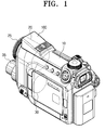
- Figure 1 is a perspective view of an image photographing apparatus having a fixed flash unit according to an embodiment of the present invention;
- Figure 2 is a perspective view of an image photographing apparatus having a popup flash unit on an upper side of the main body according to an embodiment of the present invention; and
- Figure 3 is a perspective view of an image photographing apparatus having a popup flash unit at a flank side of the main body according to an embodiment of the present invention.
-
- Throughout the drawings, like reference numerals will be understood to refer to like parts, components and structures. Well-known functions or constructions are not described in detail for brevity.
- Referring to Figure 1, an image photographing apparatus (or camera apparatus) according to an embodiment of the present invention comprises a
main body 10, a first imagephotographing device unit 20, a first image photographingdevice lens part 25, a second imagephotographing device unit 30, a second image photographingdevice lens part 35 and a fixedflash 100. - The
main body 10 forms the exterior of the camera apparatus and has a recording media (not shown) stored therein to record or playback a captured image. Themain body 10 is usually made of plastic or metal. - The first image
photographing device unit 20 operates primarily for capturing moving images. A camcorder comprises the first imagephotographing device unit 20. A portion of the first imagephotographing device unit 20 protrudes from the front of themain body 10, while the remainder of the first imagephotographing device unit 20 is located within themain body 10. The first imagephotographing device unit 20 is further configured and located on an upper part of the front of themain body 10 as shown in Figure 1. - The first image photographing
device lens part 25 captures moving images and is configured and located towards the front part of the first image photographingdevice unit 20 and protrudes from the exterior of themain body 10. - The second image photographing
device unit 30 is mounted on themain body 10 and captures still images. A digital camera comprise the second imagephotographing device unit 30. A portion of the second imagephotographing device unit 30 protrudes from the exterior of themain body 10, while the remainder of the imagephotographing device unit 30 is located within themain body 10. The second imagephotographing device unit 30 is configured and located at a lower part of the front side of themain body 10. - The second image photographing
device lens part 35 is configured and located at a front part of the second imagephotographing device unit 30 and protrudes from the exterior of themain body 10. - The
fixed flash 100 is configured and located on an upper side of themain body 10. Since thefixed flash 100 is used when a still image is photographed using the second imagephotographing device unit 30, thefixed flash 100 is configured and located on a front part of an upper side of themain body 10, so that an appropriate amount, and angle of light is imparted on a subject for capture by the second imagephotographing device unit 30. This is particularly important as the first imagephotographing device unit 25 may interfere with the light emitted by thefixed flash 100 thus causing unwanted shadows. - A camera apparatus shown in Figure 2 according to another embodiment of the present invention comprises a
popup flash 200 instead of the fixedflash 100 of Figure 1. Thepopup flash 200 is configured and located at substantially the same position as thefixed flash 100 to avoid shadows which may be generated by the first imagephotographing device unit 20. Specifically, the light of thepopup flash 200 which is provided when the popup flash appears, will be emitted at substantially the same angles as that of thefixed flash 100. Since the construction and operation of thepopup flash 200 in Figure 2 and thepopup flash 300 in Figure 3, which will be described in greater detail below, are known, a detailed description thereof will be omitted for conciseness. - Referring to Figure 3, the
popup flash 300 is configured and located on a flank side of themain body 10. In yet another embodiment of the present invention, thepopup flash 300 may be replaced with a fixed flash. - Hereinafter, the operation of the camera apparatus will be described.
- The first image
photographing device unit 20 comprises a first image photographingdevice lens part 25, a signal conversion device (not shown), and a deck (not shown), for recording and playing back photographed images. An image captured by the first image photographingdevice lens part 25 is converted into digital, magnetic, data in the signal conversion device (not shown), and this data is stored onto a magnetic tape (not shown) using the deck (not shown). The data stored on the magnetic tape is also played back through the deck (not shown). Since the construction and operating principles of the first image photographingdevice unit 20 are known, a detailed description thereof will be omitted for conciseness. - The second image
photographing device unit 30 comprises the second image photographingdevice lens part 35, a memory device (not shown), and a signal conversion device (not shown). A still image captured by the second image photographingdevice lens part 35 is converted in into a digital signal in the signal conversion device (not shown), and the digital signal is stored in the memory device (not shown). The memory device may be a hard disc (not shown) or a flash memory (not shown) or the like. Since the construction and operating principles of the second image photographingdevice unit 30 are known, the detailed description thereof will be omitted for conciseness. - An image photographing apparatus according to an embodiment of the present invention includes functions of both a digital camera and a camcorder, and therefore, a user can select the camcorder function to capture moving images if he so desires. Furthermore, a user can select the digital camera function to capture still images when the user wishes to obtain a higher quality still image. Additionally, a user is able to purchase a single product having the functions of both a camcorder and a digital camera thus reducing expenditure.
- The camera apparatus has the first image
photographing device unit 20 and the second imagephotographing device unit 30 configured and located in parallel with one another in the front of themain body 10. This allows a user to use either the camcorder or the digital camera simply by pushing a selection button (not shown). This is done without the need to change the pose of the hand supporting the device. - If the second image photographing
device unit 30 is mounted on the lower part of the front of themain body 10, it is important to match the angles of a subject and the angles offlashes device lens part 25 protrudes from an upper part of the front of themain body 10 which means that potentially, the light from any one offlashes flashes flash 100 is mounted on the upper part of themain body 10 and is raised slightly above themain body 10 to avoid the first image photographingdevice lens part 25 casting a shadow on the subject. - According to another embodiment, the
camera apparatus 10 has thepopup flash 200 instead of the fixedflash 100 and is shown in Figure 2. Thepopup flash 200 is mounted to a front part of the upper side of themain body 10 in substantially the same position as the fixedflash 100 so as to avoid the the first image photographingdevice lens part 25 casting a shadow on the subject when thepopup flash 200 is activated. - According to another embodiment of the present invention, the
camera apparatus 10 has thepopup flash 300 located on a certain area of the flank side of the main body, as is shown in Figure 3. Thepopup flash 300 is mounted to the flank side of themain body 10 to prevent the the first image photographingdevice unit 20 casting an unwanted shadow. In another embodiment, thepopup flash 300 is replaced with a fixed flash. - As described above, the camera apparatus has both the first image photographing device unit and the second image photographing device unit located on a front side of a main body allowing a user to selective between the digital camera function and the camcorder function without having to change hand position. Furthermore, the flash is mounted to the front part of an upper side of the image photographing apparatus main body so that the shadow cast by the first image photographing device is minimised or avoided. A flash can also be mounted to a flank side of the main body so that the shadow cast by the first image photographing device is minimised or avoided.
Claims (11)
- A camera apparatus (100), comprising a body (10), a camcorder element (20) and a still camera element (30), characterised by flash means (200, 300) mounted on the body (10) and being arranged to operate in conjunction with said still camera element (30).
- A camera apparatus according to claim 1, wherein either the still camera element (30) or the camcorder element (20) comprises a lens device (25, 35) protruding from the body (10), wherein the flash means (200, 300) is arranged such that light emitted therefrom is not impinged by said lens device (25, 35).
- A camera apparatus according to claim 2, wherein the flash means (200, 300) is located above the lens device (25, 35), and/or to the side of the lens device (25, 35).
- An image photographing apparatus comprising:a main body forming an external appearance of the image photographing apparatus and having a recording media for recording and reproducing an image;a first image photographing device unit mounted to the main body for photographing a moving image;a second image photographing device unit mounted to the main body for photographing a still image or a moving image; anda flash for providing a light.
- The image photographing apparatus according to claim 4, wherein the flash is mounted to a front part of an upper side of the main body to avoid shading of the light by the first image photographing device unit or the second image photographing device unit.
- The image photographing apparatus according to claim 4, wherein the first image photographing device unit comprises:a first image photographing device lens part protrusively configured and disposed at a front side of the main body to receive the moving image.
- The image photographing apparatus according to claim 6, wherein the second image photographing device unit comprises:a second image photographing device lens part protrusively configured and disposed at a front side of the main body and vertically parallel with the first image photographing device lens part to receive the still or moving image.
- The image photographing apparatus according to claim 4, wherein the flash comprises a pop up function.
- The image photographing apparatus according to claim 4, wherein the flash is mounted to a side of the main body to avoid shading of the light by the first image photographing device unit.
- An image photographing apparatus comprisinga main body forming an external appearance and having a recording media for recording and reproducing an image;a first image photographing device unit mounted to the main body for photographing a moving image;a second image photographing device unit mounted to the main body for photographing a still image or a moving image; anda flash for providing a light, mounted to a front of a flank side of the main body to avoid shading of the light by the first image photographing device unit or the second image photographing device unit.
- The image photographing apparatus according to claim 10, wherein the flash comprises a pop up function.
Applications Claiming Priority (2)
| Application Number | Priority Date | Filing Date | Title |
|---|---|---|---|
| KR1020040016193A KR20050091119A (en) | 2004-03-10 | 2004-03-10 | Image photographing apparatus |
| KR2004016193 | 2004-03-10 |
Publications (1)
| Publication Number | Publication Date |
|---|---|
| EP1575271A1 true EP1575271A1 (en) | 2005-09-14 |
Family
ID=34825211
Family Applications (1)
| Application Number | Title | Priority Date | Filing Date |
|---|---|---|---|
| EP05101477A Withdrawn EP1575271A1 (en) | 2004-03-10 | 2005-02-25 | A camera apparatus having a flash |
Country Status (5)
| Country | Link |
|---|---|
| US (1) | US20050200754A1 (en) |
| EP (1) | EP1575271A1 (en) |
| JP (1) | JP2005260951A (en) |
| KR (1) | KR20050091119A (en) |
| CN (1) | CN100403773C (en) |
Families Citing this family (5)
| Publication number | Priority date | Publication date | Assignee | Title |
|---|---|---|---|---|
| JP4381053B2 (en) * | 2003-08-07 | 2009-12-09 | 三洋電機株式会社 | Imaging device |
| KR20050090801A (en) * | 2004-03-10 | 2005-09-14 | 삼성전자주식회사 | Flash pop-up device for photographing apparatus |
| KR100813978B1 (en) * | 2006-02-22 | 2008-03-17 | 삼성전자주식회사 | Method and apparatus for recording and reproducing multimedia data |
| JP4472659B2 (en) * | 2006-04-20 | 2010-06-02 | 有限会社システムI.O | Monitoring device |
| JP4254857B2 (en) * | 2006-12-25 | 2009-04-15 | ソニー株式会社 | Imaging device |
Citations (5)
| Publication number | Priority date | Publication date | Assignee | Title |
|---|---|---|---|---|
| EP0287879A2 (en) | 1987-04-20 | 1988-10-26 | Fuji Photo Film Co., Ltd. | Camera for shooting movie and still pictures |
| JPH0545722A (en) | 1991-08-21 | 1993-02-26 | Aiwa Co Ltd | Camera apparatus |
| JP2001033866A (en) | 1999-07-22 | 2001-02-09 | Ricoh Co Ltd | Camera suitable for vertical and horizontal shooting |
| US20010040622A1 (en) * | 2000-04-12 | 2001-11-15 | Olympus Optical Co., Ltd. | Camera for both silver-salt photography and electronic image pickup |
| JP2002237987A (en) * | 2001-02-09 | 2002-08-23 | Olympus Optical Co Ltd | Camera in common use for silver halide photographing and electronic imaging |
Family Cites Families (9)
| Publication number | Priority date | Publication date | Assignee | Title |
|---|---|---|---|---|
| US5504584A (en) * | 1991-01-30 | 1996-04-02 | Fuji Photo Film Co., Ltd. | Video movie camera capable of still photography using a stroboscopic flash |
| US6037972A (en) * | 1994-10-21 | 2000-03-14 | Canon Kabushiki Kaisha | Camera |
| US6359649B1 (en) * | 1995-04-04 | 2002-03-19 | Canon Kabushiki Kaisa | Video camera integrated with still camera |
| JP2815553B2 (en) * | 1995-04-28 | 1998-10-27 | 三星電子株式会社 | Video camera with integrated still camera |
| US5926218A (en) * | 1996-06-04 | 1999-07-20 | Eastman Kodak Company | Electronic camera with dual resolution sensors |
| US6104885A (en) * | 1997-01-08 | 2000-08-15 | Eastman Kodak Company | Camera for selectively recording images on a photographic film or on a magnetic tape |
| JPH11355624A (en) * | 1998-06-05 | 1999-12-24 | Fuji Photo Film Co Ltd | Imaging equipment |
| JP3750462B2 (en) * | 2000-02-22 | 2006-03-01 | コニカミノルタフォトイメージング株式会社 | Digital camera and recording medium |
| KR20040032724A (en) * | 2002-10-09 | 2004-04-17 | 삼성전자주식회사 | Digital camcoder digital still camera |
-
2004
- 2004-03-10 KR KR1020040016193A patent/KR20050091119A/en not_active Withdrawn
-
2005
- 2005-02-08 US US11/052,292 patent/US20050200754A1/en not_active Abandoned
- 2005-02-25 EP EP05101477A patent/EP1575271A1/en not_active Withdrawn
- 2005-03-07 CN CNB2005100513075A patent/CN100403773C/en not_active Expired - Fee Related
- 2005-03-07 JP JP2005063138A patent/JP2005260951A/en active Pending
Patent Citations (5)
| Publication number | Priority date | Publication date | Assignee | Title |
|---|---|---|---|---|
| EP0287879A2 (en) | 1987-04-20 | 1988-10-26 | Fuji Photo Film Co., Ltd. | Camera for shooting movie and still pictures |
| JPH0545722A (en) | 1991-08-21 | 1993-02-26 | Aiwa Co Ltd | Camera apparatus |
| JP2001033866A (en) | 1999-07-22 | 2001-02-09 | Ricoh Co Ltd | Camera suitable for vertical and horizontal shooting |
| US20010040622A1 (en) * | 2000-04-12 | 2001-11-15 | Olympus Optical Co., Ltd. | Camera for both silver-salt photography and electronic image pickup |
| JP2002237987A (en) * | 2001-02-09 | 2002-08-23 | Olympus Optical Co Ltd | Camera in common use for silver halide photographing and electronic imaging |
Non-Patent Citations (3)
| Title |
|---|
| PATENT ABSTRACTS OF JAPAN vol. 017, no. 341 (P - 1565) 28 June 1993 (1993-06-28) * |
| PATENT ABSTRACTS OF JAPAN vol. 2000, no. 19 5 June 2001 (2001-06-05) * |
| PATENT ABSTRACTS OF JAPAN vol. 2002, no. 12 12 December 2002 (2002-12-12) * |
Also Published As
| Publication number | Publication date |
|---|---|
| CN1667492A (en) | 2005-09-14 |
| JP2005260951A (en) | 2005-09-22 |
| CN100403773C (en) | 2008-07-16 |
| KR20050091119A (en) | 2005-09-15 |
| US20050200754A1 (en) | 2005-09-15 |
Similar Documents
| Publication | Publication Date | Title |
|---|---|---|
| US8537274B2 (en) | Image capture apparatus | |
| King | Digital photography for dummies | |
| US20070194858A1 (en) | Method and apparatus for recording and reproducing multimedia data | |
| CN102970470A (en) | Image capturing device | |
| EP1575271A1 (en) | A camera apparatus having a flash | |
| US7471335B2 (en) | Imaging unit, camera body and camera system | |
| JP2008182555A (en) | Recording / playback device | |
| JPH1164928A (en) | Camera with digital memory | |
| JP2004069830A (en) | Camera | |
| US20080279537A1 (en) | Information Recording/Reproducing Apparatus | |
| US20040041922A1 (en) | Digital camera with automatic audio recording background | |
| JP2804776B2 (en) | Electronic imaging device | |
| JP2004120264A (en) | Digital camera | |
| US12155962B2 (en) | Image pickup apparatus having function of recording voice data, control method for image pickup apparatus, and storage medium | |
| JP2531713B2 (en) | Electronic camera | |
| JPH11355621A (en) | Electronic camera device | |
| JP4376758B2 (en) | Video recording / reproducing method and video recording / reproducing apparatus | |
| US20070071395A1 (en) | Digital camcorder design and method for capturing historical scene data | |
| JP3139048B2 (en) | Electronic still camera | |
| JP2009218853A (en) | Image processor | |
| KR101193458B1 (en) | Digital imaging device comprising a speaker | |
| JPH0523020Y2 (en) | ||
| JP2007180835A (en) | Portable imaging device | |
| JPS6062282A (en) | Electronic camera | |
| King et al. | Digital Cameras and Equipment For Dummies |
Legal Events
| Date | Code | Title | Description |
|---|---|---|---|
| PUAI | Public reference made under article 153(3) epc to a published international application that has entered the european phase |
Free format text: ORIGINAL CODE: 0009012 |
|
| AK | Designated contracting states |
Kind code of ref document: A1 Designated state(s): AT BE BG CH CY CZ DE DK EE ES FI FR GB GR HU IE IS IT LI LT LU MC NL PL PT RO SE SI SK TR |
|
| AX | Request for extension of the european patent |
Extension state: AL BA HR LV MK YU |
|
| 17P | Request for examination filed |
Effective date: 20051014 |
|
| AKX | Designation fees paid |
Designated state(s): DE GB NL |
|
| 17Q | First examination report despatched |
Effective date: 20071127 |
|
| STAA | Information on the status of an ep patent application or granted ep patent |
Free format text: STATUS: THE APPLICATION IS DEEMED TO BE WITHDRAWN |
|
| 18D | Application deemed to be withdrawn |
Effective date: 20090901 |