EP1575196A1 - Dispersion compensating fiber module - Google Patents
Dispersion compensating fiber module Download PDFInfo
- Publication number
- EP1575196A1 EP1575196A1 EP05290499A EP05290499A EP1575196A1 EP 1575196 A1 EP1575196 A1 EP 1575196A1 EP 05290499 A EP05290499 A EP 05290499A EP 05290499 A EP05290499 A EP 05290499A EP 1575196 A1 EP1575196 A1 EP 1575196A1
- Authority
- EP
- European Patent Office
- Prior art keywords
- dispersion
- module
- compensating fiber
- dispersion compensating
- dcf
- Prior art date
- Legal status (The legal status is an assumption and is not a legal conclusion. Google has not performed a legal analysis and makes no representation as to the accuracy of the status listed.)
- Granted
Links
- 239000006185 dispersion Substances 0.000 title claims abstract description 246
- 239000000835 fiber Substances 0.000 title claims abstract description 87
- 230000005540 biological transmission Effects 0.000 claims abstract description 89
- 239000013307 optical fiber Substances 0.000 claims abstract description 71
- 230000003287 optical effect Effects 0.000 claims description 28
- 238000001069 Raman spectroscopy Methods 0.000 claims description 9
- 230000005284 excitation Effects 0.000 claims description 6
- 230000001747 exhibiting effect Effects 0.000 claims 2
- 238000005253 cladding Methods 0.000 description 8
- 238000000034 method Methods 0.000 description 8
- 238000010586 diagram Methods 0.000 description 7
- 238000005452 bending Methods 0.000 description 5
- 230000000994 depressogenic effect Effects 0.000 description 4
- 239000008186 active pharmaceutical agent Substances 0.000 description 3
- 230000008901 benefit Effects 0.000 description 2
- 230000000052 comparative effect Effects 0.000 description 2
- 230000000694 effects Effects 0.000 description 2
- 238000004519 manufacturing process Methods 0.000 description 2
- 238000007792 addition Methods 0.000 description 1
- XAGFODPZIPBFFR-UHFFFAOYSA-N aluminium Chemical compound [Al] XAGFODPZIPBFFR-UHFFFAOYSA-N 0.000 description 1
- 229910052782 aluminium Inorganic materials 0.000 description 1
- 238000005229 chemical vapour deposition Methods 0.000 description 1
- 238000004891 communication Methods 0.000 description 1
- 238000000151 deposition Methods 0.000 description 1
- 230000008021 deposition Effects 0.000 description 1
- 230000006866 deterioration Effects 0.000 description 1
- 238000002022 differential scanning fluorescence spectroscopy Methods 0.000 description 1
- 238000005516 engineering process Methods 0.000 description 1
- 238000012986 modification Methods 0.000 description 1
- 230000004048 modification Effects 0.000 description 1
- 238000006467 substitution reaction Methods 0.000 description 1
- 239000012808 vapor phase Substances 0.000 description 1
Images




Classifications
-
- G—PHYSICS
- G02—OPTICS
- G02B—OPTICAL ELEMENTS, SYSTEMS OR APPARATUS
- G02B6/00—Light guides; Structural details of arrangements comprising light guides and other optical elements, e.g. couplings
- G02B6/24—Coupling light guides
- G02B6/26—Optical coupling means
- G02B6/28—Optical coupling means having data bus means, i.e. plural waveguides interconnected and providing an inherently bidirectional system by mixing and splitting signals
- G02B6/293—Optical coupling means having data bus means, i.e. plural waveguides interconnected and providing an inherently bidirectional system by mixing and splitting signals with wavelength selective means
- G02B6/29371—Optical coupling means having data bus means, i.e. plural waveguides interconnected and providing an inherently bidirectional system by mixing and splitting signals with wavelength selective means operating principle based on material dispersion
- G02B6/29374—Optical coupling means having data bus means, i.e. plural waveguides interconnected and providing an inherently bidirectional system by mixing and splitting signals with wavelength selective means operating principle based on material dispersion in an optical light guide
- G02B6/29376—Optical coupling means having data bus means, i.e. plural waveguides interconnected and providing an inherently bidirectional system by mixing and splitting signals with wavelength selective means operating principle based on material dispersion in an optical light guide coupling light guides for controlling wavelength dispersion, e.g. by concatenation of two light guides having different dispersion properties
- G02B6/29377—Optical coupling means having data bus means, i.e. plural waveguides interconnected and providing an inherently bidirectional system by mixing and splitting signals with wavelength selective means operating principle based on material dispersion in an optical light guide coupling light guides for controlling wavelength dispersion, e.g. by concatenation of two light guides having different dispersion properties controlling dispersion around 1550 nm, i.e. S, C, L and U bands from 1460-1675 nm
-
- G—PHYSICS
- G02—OPTICS
- G02B—OPTICAL ELEMENTS, SYSTEMS OR APPARATUS
- G02B6/00—Light guides; Structural details of arrangements comprising light guides and other optical elements, e.g. couplings
- G02B6/02—Optical fibres with cladding with or without a coating
- G02B6/02214—Optical fibres with cladding with or without a coating tailored to obtain the desired dispersion, e.g. dispersion shifted, dispersion flattened
- G02B6/02219—Characterised by the wavelength dispersion properties in the silica low loss window around 1550 nm, i.e. S, C, L and U bands from 1460-1675 nm
- G02B6/02228—Dispersion flattened fibres, i.e. having a low dispersion variation over an extended wavelength range
- G02B6/02238—Low dispersion slope fibres
- G02B6/02242—Low dispersion slope fibres having a dispersion slope <0.06 ps/km/nm2
-
- G—PHYSICS
- G02—OPTICS
- G02B—OPTICAL ELEMENTS, SYSTEMS OR APPARATUS
- G02B6/00—Light guides; Structural details of arrangements comprising light guides and other optical elements, e.g. couplings
- G02B6/02—Optical fibres with cladding with or without a coating
- G02B6/02214—Optical fibres with cladding with or without a coating tailored to obtain the desired dispersion, e.g. dispersion shifted, dispersion flattened
- G02B6/02219—Characterised by the wavelength dispersion properties in the silica low loss window around 1550 nm, i.e. S, C, L and U bands from 1460-1675 nm
- G02B6/02252—Negative dispersion fibres at 1550 nm
- G02B6/02261—Dispersion compensating fibres, i.e. for compensating positive dispersion of other fibres
-
- G—PHYSICS
- G02—OPTICS
- G02B—OPTICAL ELEMENTS, SYSTEMS OR APPARATUS
- G02B6/00—Light guides; Structural details of arrangements comprising light guides and other optical elements, e.g. couplings
- G02B6/02—Optical fibres with cladding with or without a coating
- G02B6/02214—Optical fibres with cladding with or without a coating tailored to obtain the desired dispersion, e.g. dispersion shifted, dispersion flattened
- G02B6/02219—Characterised by the wavelength dispersion properties in the silica low loss window around 1550 nm, i.e. S, C, L and U bands from 1460-1675 nm
- G02B6/02266—Positive dispersion fibres at 1550 nm
- G02B6/02271—Non-zero dispersion shifted fibres, i.e. having a small positive dispersion at 1550 nm, e.g. ITU-T G.655 dispersion between 1.0 to 10 ps/nm.km for avoiding nonlinear effects
-
- G—PHYSICS
- G02—OPTICS
- G02B—OPTICAL ELEMENTS, SYSTEMS OR APPARATUS
- G02B6/00—Light guides; Structural details of arrangements comprising light guides and other optical elements, e.g. couplings
- G02B6/02—Optical fibres with cladding with or without a coating
- G02B6/02214—Optical fibres with cladding with or without a coating tailored to obtain the desired dispersion, e.g. dispersion shifted, dispersion flattened
- G02B6/0228—Characterised by the wavelength dispersion slope properties around 1550 nm
-
- G—PHYSICS
- G02—OPTICS
- G02B—OPTICAL ELEMENTS, SYSTEMS OR APPARATUS
- G02B6/00—Light guides; Structural details of arrangements comprising light guides and other optical elements, e.g. couplings
- G02B6/02—Optical fibres with cladding with or without a coating
- G02B6/036—Optical fibres with cladding with or without a coating core or cladding comprising multiple layers
- G02B6/03616—Optical fibres characterised both by the number of different refractive index layers around the central core segment, i.e. around the innermost high index core layer, and their relative refractive index difference
- G02B6/03661—Optical fibres characterised both by the number of different refractive index layers around the central core segment, i.e. around the innermost high index core layer, and their relative refractive index difference having 4 layers only
- G02B6/03666—Optical fibres characterised both by the number of different refractive index layers around the central core segment, i.e. around the innermost high index core layer, and their relative refractive index difference having 4 layers only arranged - + - +
-
- H—ELECTRICITY
- H04—ELECTRIC COMMUNICATION TECHNIQUE
- H04B—TRANSMISSION
- H04B10/00—Transmission systems employing electromagnetic waves other than radio-waves, e.g. infrared, visible or ultraviolet light, or employing corpuscular radiation, e.g. quantum communication
- H04B10/25—Arrangements specific to fibre transmission
- H04B10/2507—Arrangements specific to fibre transmission for the reduction or elimination of distortion or dispersion
- H04B10/2513—Arrangements specific to fibre transmission for the reduction or elimination of distortion or dispersion due to chromatic dispersion
- H04B10/2525—Arrangements specific to fibre transmission for the reduction or elimination of distortion or dispersion due to chromatic dispersion using dispersion-compensating fibres
-
- G—PHYSICS
- G02—OPTICS
- G02B—OPTICAL ELEMENTS, SYSTEMS OR APPARATUS
- G02B6/00—Light guides; Structural details of arrangements comprising light guides and other optical elements, e.g. couplings
- G02B6/02—Optical fibres with cladding with or without a coating
- G02B6/02214—Optical fibres with cladding with or without a coating tailored to obtain the desired dispersion, e.g. dispersion shifted, dispersion flattened
- G02B6/02219—Characterised by the wavelength dispersion properties in the silica low loss window around 1550 nm, i.e. S, C, L and U bands from 1460-1675 nm
- G02B6/02228—Dispersion flattened fibres, i.e. having a low dispersion variation over an extended wavelength range
- G02B6/02233—Dispersion flattened fibres, i.e. having a low dispersion variation over an extended wavelength range having at least two dispersion zero wavelengths
-
- G—PHYSICS
- G02—OPTICS
- G02B—OPTICAL ELEMENTS, SYSTEMS OR APPARATUS
- G02B6/00—Light guides; Structural details of arrangements comprising light guides and other optical elements, e.g. couplings
- G02B6/02—Optical fibres with cladding with or without a coating
- G02B6/028—Optical fibres with cladding with or without a coating with core or cladding having graded refractive index
- G02B6/0281—Graded index region forming part of the central core segment, e.g. alpha profile, triangular, trapezoidal core
Definitions
- the invention relates to a dispersion compensating fiber module which is used for compensating the accumulated chromatic dispersion of a non-zero dispersion shifted optical fiber (NZ-DSF) which has chromatic dispersion of several ps/nm/km in the C-band (wavelength between 1.525 ⁇ m and 1.565 ⁇ m) and in the L-band (wavelength between 1.565 ⁇ m and 1.625 ⁇ m). More particularly, the invention relates to a dispersion compensating fiber module which is capable of suppressing residual dispersion to a low level, and to an optical fiber transmission line which is fabricated by connecting such a module to a transmission optical fiber.
- NZ-DSF non-zero dispersion shifted optical fiber
- dispersion compensation for each span becomes indispensable. Since such dispersion compensation is required over the entire operating wavelength range, it also becomes necessary to compensate the accumulated dispersion slope of the transmission line at the same time.
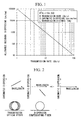
- FIG. 2 is a schematic diagram illustrating the basic concept of compensation for chromatic dispersion upon an optical fiber transmission line.
- a transmission optical fiber typically has a chromatic dispersion and a dispersion slope in both positive values. Therefore, it is possible to compensate the dispersion in a wide wavelength range by connecting an SC-DCF which has a negative chromatic dispersion and a negative dispersion slope having an appropriate length (i.e., a length in which the dispersion can be cancelled) with the ratio of the chromatic dispersion and the dispersion slope being appropriately adjusted.
- the dispersion characteristic is a curved line, rather than such a linear line.
- the wavelength dependence of the dispersion slope of the transmission optical fiber is small as compared to that of the SC-DCF, the wavelength dependence of the SC-DCF is still comparatively large.
- the greater the relative dispersion slope (RDS) with respect to the chromatic dispersion the greater the wavelength dependence of the dispersion slope becomes.
- FIGS. 3 and 4 are graphs showing examples of the residual dispersion characteristics when lengths of 80 km of various types of NZ-DSF, which are described in the above-described paper by Aikawa, have been dispersion compensated.
- FIG. 3 the residual dispersion characteristic after a low dispersion slope type NZ-DSF has been compensated with an SC-DCF module is shown.
- the residual dispersion is less than or equal to ⁇ 5 ps/nm, and thus, it is possible to compensate the residual dispersion so that it is reduced over the entire wavelength range.
- An SC-DCF has a refractive index profile as, for example, shown in FIG. 5.
- ⁇ the delta
- ⁇ the ratio of the radii of the respective layers of this refractive index profile
- the design for this adjustment of the RDS and fabrication of such fibers can be achieved comparatively easily.
- an SC-DCF having the RDS exceeds 0.01 nm -1 , an attempt is made to maintain the bending loss and the cutoff wavelength and the like while making the absolute value of the chromatic dispersion great, the design and the fabrication become difficult, and furthermore the dispersion curve easily becomes severely curved.
- the invention has been made in the light of the above identified problems, and it takes as one object to provide an SC-DCF module which is capable of compensating for the accumulated chromatic dispersion of an NZ-DSF in the C-band or the L-band, thus extending the transmission distance of a long haul transmission line, and an optical fiber transmission line which includes this SC-DCF module.
- one aspect of the invention provides an SC-DCF module which, when connected to an optical fiber which exhibits, at a wavelength of 1.55 ⁇ m, a chromatic dispersion of between +2 and +6 ps/nm/km, a dispersion slope of between +0.075 ps/nm 2 /km and +0.095 ps/nm 2 /km, and an RDS of between 0.016 nm -1 and 0.024 nm -1 , performs compensation so that the residual dispersion of the connected optical fiber is reduced, the SC-DCF module including an SC-DCF and at least one optical fiber fused to the dispersion compensating fiber, wherein the SC-DCF module exhibits at a wavelength of 1.55 ⁇ m, an RDS of between 0.016 nm -1 and 0.026 nm -1 ; in a wavelength range between 1.525 ⁇ m and 1.565 ⁇ m, a maximum residual dispersion difference, when converted per km of the transmission optical
- the SC-DCF exhibits, at a wavelength of 1.55 ⁇ m, a chromatic dispersion and a dispersion slope of negative values, and an RDS of between 0.006 nm -1 and 0.016 nm -1 ; and the optical fiber exhibits, at a wavelength of 1.55 ⁇ m, a chromatic dispersion and a dispersion slope of positive values, and an RDS of between 0.0028 nm -1 and 0.0036 nm -1 .
- a total length of the fibers in an SC-DCF module and a dispersion compensated fiber per -100 ps/nm may be less than or equal to 40 km
- a reel is further provided and the SC-DCF is wound about the reel.
- another aspect of the invention provides an SC-DCF module which, when connected to an optical fiber which exhibits, at a wavelength of 1.59 ⁇ m, a chromatic dispersion of between +6 and +10 ps/nm/km, a dispersion slope of between +0.075ps/nm 2 /km and +0.095 ps/nm 2 /km, and an RDS of between 0.008 nm -1 and 0.014 nm -1 , performs compensation so that the residual dispersion of the connected optical fiber is reduced
- the SC-DCF module includes an SC-DCF and at least one optical fiber fused to the dispersion compensating fiber, wherein the SC-DCF module exhibits at a wavelength of 1.59 ⁇ m, an RDS of between 0.008 nm -1 and 0.014 mn -1 ; in a wavelength range between 1.565 ⁇ m and 1.625 ⁇ m, a maximum residual dispersion difference, when converted per
- the SC-DCF exhibits, at a wavelength of 1.59 ⁇ m, a chromatic dispersion and a dispersion slope of negative values, and an RDS of between 0.005 nm -1 and 0.01 nm -1 ; and the optical fiber exhibits, at a wavelength of 1.59 ⁇ m, a chromatic dispersion and a dispersion slope of positive values, and an RDS of between 0.0026 nm -1 and 0.0034 nm -1 .
- a total length of the fibers in the SC-DCF module per -100 ps/nm may be less than or equal to 30 km.
- a reel is included and the SC-DCF is wound about the reel.
- yet another aspect of the invention provides an optical fiber transmission line, including any of the above-described SC-DCF modules, and a transmission optical fiber which is connected to this SC-DCF module.
- the SC-DCF module of the invention when connected to an optical fiber which exhibits, at a wavelength of 1.55 5 ⁇ m, a chromatic dispersion of between +2 and +6 ps/nm/km, a dispersion slope of between +0.075 ps/nm 2 /km and +0.095 ps/nm 2 /km, and an RDS of between 0.016 nm -1 and 0.024 nm -1 , performs compensation so that the residual dispersion of the connected optical fiber is reduced, the SC-DCF module exhibits, at a wavelength of 1.55 ⁇ m, an RDS of between 0.016 nm -1 and 0.026 nm -1 ; in a wavelength range between 1.525 ⁇ m and 1.565 ⁇ m, a maximum residual dispersion difference, when converted per km of the transmission optical fiber, of less than or equal to 0.4 ps/nm/km. Accordingly, the transmission distance of a long haul transmission line, for which the residual dispersion of
- the SC-DCF module of the invention when connected to an optical fiber which exhibits, at a wavelength of 1.59 ⁇ m, a chromatic dispersion of between +6 ps/nm/km and +10 ps/nm/km, a dispersion slope of between +0.075 ps/nm 2 /km and +0.095 ps/nm 2 /km, and an RDS of between 0.008 nm -1 and 0.014 nm -1 , performs compensation so that the residual dispersion of the connected optical fiber is reduced, and the SC-DCF module exhibits, at a wavelength of 1.59 ⁇ m, an RDS of between 0.008 nm -1 and 0.014 mn -1 ; in a wavelength range between 1.565 ⁇ m and 1.625 ⁇ m, a maximum residual dispersion difference, when converted per km of the transmission optical fiber, of less than or equal to 0.3 ps/nm/km. Accordingly, the transmission distance of a long haul,
- this optical fiber transmission line there is connected to the transmission optical fiber an SC-DCF module whose residual dispersion is smaller than is the case when a conventional SC-DCF module is used, accordingly, as compared to the case when a conventional SC-DCF module is used, it is possible to make the transmission distance longer, and/or to eliminate a supplementary dispersion compensating unit, so that it is possible to reduce cost.
- FIG. 1 is a graph showing a relationship between transmission rate and residual dispersion
- FIG. 3 is a graph showing a residual dispersion characteristic after a low dispersion slope type NZ-DSF has been compensated with an SC-DCF module;
- FIG. 4 is a graph showing a residual dispersion characteristic after a high dispersion slope type NZ-DSF has been compensated with an SC-DCF module;
- FIG. 5 is a schematic diagram showing an example of a cross sectional refractive index profile of an SC-DCF
- FIG. 6 is a graph showing the chromatic dispersion characteristic of a fiber A which is used in an exemplary embodiment of the invention.
- FIG. 7 is a graph showing the chromatic dispersion characteristic of SC-DCFs B, C, and D which are used in an exemplary embodiment of the invention.
- FIG. 8 is a graph showing the residual dispersion characteristic when the accumulated chromatic dispersion of an 80 km long large effective area NZ-DSF has been compensated by using these SC-DCF modules B, C, and D which are used in an exemplary embodiment of the present invention
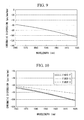
- FIG. 9 is a graph showing the chromatic dispersion characteristic of a fiber E which is used in an exemplary embodiment of the invention.
- FIG. 10 is a graph showing the chromatic dispersion characteristic of SC-DCFs F, G, and H which are used in an exemplary embodiment of the invention.
- FIG. 11 is a graph showing the residual dispersion characteristic when the accumulated chromatic dispersion of a 80 km long large effective area NZ-DSF has been compensated by using these SC-DCF modules F, G, and H which are used in an exemplary embodiment of the invention.
- FIG. 12 is a schematic inner view illustrating the SC-DCF module of a first exemplary embodiment of the invention.
- FIG. 13 is a cross-sectional view taken along line A-A' in FIG. 12;
- FIG. 14 is a schematic diagram of a first exemplary embodiment of an optical transmission system.
- FIG. 15 is a schematic diagram of a second exemplary embodiment of an optical transmission system.
- a connector 14 may be provided to an end of each of the single-mode fibers 12 for connecting SC-DCF module 10 to transmission optical fibers or the like.
- adaptors may be provided and may be interposed between one of the connectors 14 and connectors of fibers that are to be connected to the module 10.
- the adaptors typically are connected to the casing 16.
- the length of the SC-DCF 11 is determined according to the amount of compensation to be achieved. Note that the SC-DCF module of the invention is not limited to this configuration.
- this SC-DCF module When this SC-DCF module is connected to an optical fiber which exhibits, at a wavelength of 1.55 ⁇ m, a chromatic dispersion of between +2 ps/nm/km and +6 ps/nm/km, a dispersion slope of between +0.075 ps/nm 2 /km and +0.095 ps/nm 2 /km, and an RDS of between 0.016 nm -1 and 0.024 nm -1 .
- the SC-DCF module performs compensation so that the residual dispersion of the connected optical fiber is reduced.
- the SC-DCF module of this exemplary embodiment may be fabricated by using an SC-DCF which has a refractive index profile as shown in FIG. 5.
- This SC-DCF includes a core 1 and a cladding 2.
- the core 1 includes a central core region 3 which has a refractive index which is greater than the refractive index of the cladding 2; a depressed core region 4 which is provided around this central core region 3 and which has a refractive index which is smaller than the refractive index of the cladding 2; a ring core region 5 which is provided around this depressed core region 4 and which has a refractive index which is greater than the refractive index of the cladding 2; and a depressed cladding region 6 which is provided around this ring core region 5 and which has a refractive index which is smaller than the refractive index of the cladding 2.
- the cladding 2 is provided around the depressed cladding region 6.
- a second exemplary embodiment of the invention is an SC-DCF module that includes an SC-DCF that exhibits, at a wavelength of 1.55 ⁇ m, a chromatic dispersion and a dispersion slope of negative values, and an RDS of between 0.006 nm -1 and 0.016 nm -1 ; and an optical fiber which exhibits, at a wavelength of 1.55 ⁇ m, a chromatic dispersion and a dispersion slope of positive values, and an RDS of between 0.0028 nm -1 and 0.0036 nm -1 .
- This SC-DCF module provides similar advantageous effects, as the first exemplary embodiment described above.
- a third exemplary embodiment of the invention is an SC-DCF module of the first exemplary or second exemplary embodiment described above, in which the total length of the fibers in the SC-DCF module per -100 ps/nm is less than or equal to 40 km.
- L Total L DCF + L SMF
- L DCF L DCF + L SMF
- L DCF L DCF + L SMF
- L DCF the length of the SC-DCF (km)
- L SMF the length of the S-SMF(km)
- D DCF the chromatic dispersion of the SC-DCF (ps/nm/km)
- D SMF the chromatic dispersion of the S-SMF (ps/nm/km).
- the size of the casing for this SC-DCF module becomes greater than that of conventional ones, which is undesirable, since it entails increase of cost and the like. It is thus desirable for the total length of the fibers per -100 ps/nm to be less than or equal to 40 km, although it depends on the amount of compensation, since it is possible to house this SC-DCF module in a casing of size which is comparable to that of a conventional SC-DCF module. It should be understood that the size of such a casing for a conventional SC-DCF module is, for example, about 224 mm ⁇ 235 mm ⁇ 45 mm.
- a fourth exemplary embodiment of the invention is an SC-DCF module.
- This compensating fiber module has a similar structure as the SC-DCF module of the first exemplary embodiment shown in FIG. 12.
- this SC-DCF module is connected to an optical fiber which exhibits, at a wavelength of 1.59 ⁇ m, a chromatic dispersion of between +6 ps/nm/km and +10 ps/nm/km, a dispersion slope of between +0.075 ps/nm 2 /km and 0.095 ps/nm 2 /km, and an RDS of between 0.008 nm -1 and 0.014 m -1 , the dispersion fiber module performs compensation so that the residual dispersion of the connected optical fiber is reduced.
- the SC-DCF module exhibits, at a wavelength of 1.59 ⁇ m, an RDS of between 0.008 nm -1 and 0.014 nm -1 , and, in a wavelength range between 1.565 ⁇ m and 1.625 ⁇ m (L-band), a maximum residual dispersion difference, when converted per km of the transmission optical fiber, of less than or equal to 0.3 ps/nm/km.
- a fifth exemplary embodiment of the invention is an SC-DCF module that includes an SC-DCF which exhibits, at a wavelength of 1.59 ⁇ m, a chromatic dispersion and a dispersion slope of negative values, and an RDS of between 0.005 nm -1 and 0.01 nm -1 ; and an optical fiber which exhibits, at a wavelength of 1.59 ⁇ m, a chromatic dispersion and a dispersion slope of positive values, and an RDS of between 0.0026 nm -1 and 0.0034 nm -1 .
- This SC-DCF module provides similar advantageous effects, as the fourth exemplary embodiment described above.
- a sixth exemplary embodiment of the invention is an SC-DCF module of the fourth exemplary or the fifth exemplary embodiment described above, in which the total length of the fibers in the SC-DCF module per -100 ps/nm is less than or equal to 30 km.
- the size of the casing for this SC-DCF module becomes greater than that of conventional ones, which is undesirable, since it entails increase of cost and the like. It is thus desirable for the total length of the fibers per -100 ps/nm to be less than or equal to 30 km, although it depends on the amount of compensation, since it is possible to house this SC-DCF module in a casing of size which is comparable to that of a conventional SC-DCF module.
- the amount of dispersion compensation which is required becomes greater. Due to this, for the same dispersion compensation amount, it is desirable for a total length of fiber which is used for the wavelength range between 1.565 ⁇ m and 1.625 ⁇ m to be shorter, than a fiber which is used for the wavelength range between 1.525 ⁇ m and 1.565 ⁇ m.
- the SC-DCF module of this seventh exemplary embodiment it is possible to obtain Raman gain effectively by disposing the SC-DCF which has smaller effective area (A eff ) and a larger non-linear refractive index (n 2 ) at the excitation optical input end at the optical excitation input power is high, as compared to an optical fiber which exhibits a chromatic dispersion and a dispersion slope of positive values.
- An eighth exemplary embodiment of the invention is an optical fiber transmission line, including an SC-DCF module according to the invention as described above, and a transmission optical fiber which is connected to the above-described SC-DCF modules.
- FIG. 14 is a schematic diagram of a first exemplary embodiment of an optical transmission system 20.
- reference numeral 21 indicates a transmission optical fiber, and a dispersion compensating fiber module 22 may be connected to every span of this transmission optical fiber 21.
- One set of an optical transmission line span may be formed by this transmission optical fiber 21 and the dispersion compensating fiber module 22, and the optical transmission line 25 of the exemplary embodiment may be formed by connecting this set of an optical transmission span in at least one stage.
- a transmitter 23 and a receiver 24 may be connected by the optical transmission line 25 to form an optical transmission system 20.
- FIG. 15 is a schematic diagram of second exemplary embodiment of optical transmission system 30.
- reference numeral 21 represents a transmission optical fiber
- a dispersion compensating fiber module 22 may be connected to every span of this transmission optical fiber 21.
- One set of a transmission line span may be formed by this transmission optical fiber 21 and the dispersion compensating fiber module 22, and this one set of transmission line span may be connected in at least one stage to form the optical transmission line 25 of the exemplary embodiment.
- the transmitter 23 and the receiver 24 are connected to this optical transmission line 25 to form an optical transmission system 30, in the optical transmission system 30 of this example, the optical signal may be received with the receiver 24 by extracting the optical signal at an intermediate transmission line span, or the transmitter 23 may be provided at an intermediate point, and the optical signal is sent out from this transmitter 23.
- the optical transmission line of the invention is not limited to these configurations.
- an SC-DCF module is connected whose residual dispersion is smaller than is the case when a conventional SC-DCF module is used, accordingly, as compared to the case when a conventional SC-DCF module is used, it is possible to make the transmission distance longer, or to eliminate an additional dispersion compensating unit, so that it is possible to reduce cost.
- Fiber A (hereinafter simply referred to as "Fiber A") having a refractive index profile as shown in FIG. 5 was fabricated by the vapor phase axial deposition (VAD) method or the modified chemical vapor deposition (MCVD) method or the like. Fiber A was fabricated so that ⁇ 1, ⁇ 2, ⁇ 3, ⁇ 4, b/a, c/b, d/c, and the core radius "d" had the values listed in Table 1.
- Module A An SC-DCF module (referred to as "Module A") which was fabricated by using Fiber A.
- the absolute value of the maximum residual dispersion in these bands was 20 ps/nm.
- SC-DCFs B, C, and D (hereinafter simply referred to as "Fiber B,” “Fiber C,” and “Fiber D,” respectively) having refractive index profiles as shown in FIG. 5 were fabricated by the well-known VAD method or the MCVD method or the like. Fibers B, C, and D were fabricated so that ⁇ 1, ⁇ 2, ⁇ 3, ⁇ 4, b/a, c/b, d/c, and the core radius "d" had the values listed in Table 3.
- Fibers B, C, and D The optical properties of Fibers B, C, and D are listed in Table 4. Furthermore, the chromatic dispersion characteristic of Fibers B, C, and D are shown in Fig. 7. SC-DCF modules (hereinafter referred to as "Module B,” “Module C,” and “Module D,” respectively) were fabricated by connecting an S-SMF to Fibers B, C, and D. The residual dispersion characteristics, when the accumulated chromatic dispersion of a large effective area NZ-DSF which was 80 km long was compensated by using Modules B, C, and D, were evaluated. The results are listed in Table 5 and FIG. 8.
- the maximum residual dispersion differences for each of these bands are 27 ps/nm for Module B, 29 ps/nm for Module C and, 31 ps/nm for Module D, respectively; and, when these are converted into values per km of the transmission optical fiber, they yield respective values of 0.34 ps/nm/km, 0.37 ps/nm/km, and 0.39 ps/nm/km, respectively.
- the SC-DCF modules could reduce the maximum residual dispersion difference to 67.5%, 72.5%, and 77.5%, respectively, with respect to the residual dispersion characteristic.
- Module E An SC-DCF module (referred to as "Module E") which was fabricated by using Fiber E.
- the maximum residual dispersion differences in these bands was, at a maximum, 30 ps/nm.
- SC-DCFs F, G, and H (hereinafter simply referred to as "Fibers F,” “Fiber G,” and “Fiber H,” respectively) having refractive index profiles as shown in FIG. 5 were fabricated by the VAD method or the MCVD method or the like. Fibers F, G, and H were fabricated so that ⁇ 1, ⁇ 2, ⁇ 3, ⁇ 4, b/a, c/b, d/c, and the core radius "d" had the values listed in Table 8.
- the optical properties of Fibers F, G, and H are listed in Table 9. Furthermore, the chromatic dispersion characteristic of Fibers F, G, and H are shown in Fig. 10. SC-DCF modules (hereinafter referred to as "Module F,” “Module G,” and “Module H,” respectively) were fabricated by connecting an S-SMF to Fibers F, G, and H. The residual dispersion characteristics, when the accumulated chromatic dispersion of a large effective area NZ-DSF which was 80 km long was compensated by using Modules F, G, and H, were evaluated. The results are listed in Table 10 and FIG. 11.
- the maximum residual dispersion differences for each of these bands are 28 ps/nm for Module F, 26 ps/nm for Module G and, 15 ps/nm for Module H, respectively; and, when these are converted into values per km of the transmission optical fiber, they yield respective values of 0.35 ps/nm/km, 0.33 ps/nm/km, and 0.19 ps/nm/km, respectively.
- the SC-DCF modules could reduce the maximum residual dispersion difference to 92%, 87%, and 50%, respectively, with respect to the residual dispersion characteristic.
Landscapes
- Chemical & Material Sciences (AREA)
- Dispersion Chemistry (AREA)
- Physics & Mathematics (AREA)
- General Physics & Mathematics (AREA)
- Optics & Photonics (AREA)
- Electromagnetism (AREA)
- Engineering & Computer Science (AREA)
- Computer Networks & Wireless Communication (AREA)
- Signal Processing (AREA)
- Optical Communication System (AREA)
- Optical Fibers, Optical Fiber Cores, And Optical Fiber Bundles (AREA)
Abstract
Description
| No | Δ1 [%] | Δ2 [%] | Δ3 [%] | Δ4 [%] | b/a | c/b | d/c | d [µm] |
| Fiber A | 1.89 | -1.20 | 0.46 | -0.05 | 2.5 | 1.4 | 1.6 | 12.0 |
| No | λ [µm] | CD [ps/nm/k m] | Trans. Loss [dB/km] | DS2) [ps/nm2/k m] | FOM3) [ps/nm/dB] | RDS [nm-1] | Aeff [µm2] | Bending Loss [dB/m, 2R=20mm] | PMD4) [ps/√km] |
| Fiber A | 1.55 | -77 | 0.60 | -1.6 | 128 | 0.020 | 12 | 2.1 | 0.11 |
| No | Δ1 [%] | Δ2 [%] | Δ3 [%] | Δ4 [%] | b/a | c/b | d/c | d [µm] |
| Fiber B | 1.49 | -0.77 | 0.43 | -0.10 | 2.5 | 1.4 | 1.6 | 13.2 |
| Fiber C | 1.47 | -0.75 | 0.43 | -0.10 | 2.5 | 1.4 | 1.6 | 13.4 |
| Fiber D | 1.53 | -0.57 | 0.34 | -0.05 | 2.6 | 1.4 | 1.6 | 11.8 |
| No | λ [µm] | CD [ps/nm/k m] | Trans. Loss [dB/km] | DS [ps/nm2/k m] | FOM [ps/nm/dB] | RDS [nm-1] | Aeff [µm2] | Bending Loss [dB/m, 2R=20mm] | PMD [ps/√km] |
| Fiber B | 1.55 | -98.7 | 0.37 | -1.13 | 267 | 0.011 | 18 | 0.8 | 0.08 |
| Fiber C | 1.55 | -68.9 | 0.35 | -0.79 | 197 | 0.012 | 17 | 1.2 | 0.10 |
| Fiber D | 1.55 | -80.6 | 0.34 | -0.53 | 237 | 0.0066 | 18 | 0.3 | 0.08 |
| No | λ [µm] | Total CD [ps/m] | RDS [mn-1] | DCF Length [km] | Loss [dB] | S-SMF Length [km] | Max. Residual Diff. [ps/nm] | Length of Fiber per -100ps/nm [km] | Loss per -100ps/nm [dB] |
| Module B | 1.55 | -324 | 0.024 | 8.1 | 9.1 | 28.0 | 27 | 11.1 | 2.8 |
| Module C | 1.55 | -325 | 0.024 | 11.6 | 10.1 | 27.8 | 29 | 12.2 | 3.1 |
| Module D | 1.55 | -321 | 0.023 | 23.4 | 26.2 | 91.7 | 31 | 35.9 | 8.2 |
| No | Δ1 [%] | Δ2 [%] | Δ3 [%] | Δ4 [%] | b/a | c/b | d/c | d [µm] |
| Fiber E | 1.71 | -0.87 | 0.44 | -0.12 | 2.5 | 1.5 | 1.6 | 13.2 |
| No | λ [µm] | CD [ps/nm/k m] | Trans. Loss [dB/km] | DS [ps/nm2/k m] | FOM [ps/nm/dB] | RDS [nm-1] | Aeff [µm2] | Bending Loss [dB/m, 2R=20mm] | PMD [ps/√km] |
| Fiber E | 1.59 | -74 | 0.41 | -0.81 | 180 | 0.011 | 16 | 0.8 | 0.09 |
| No | Δ1 [%] | Δ2 [%] | Δ3 [%] | Δ4 [%] | b/a | c/b | d/c | d [µm] |
| Fiber F | 1.69 | -0.73 | 0.41 | -0.08 | 2.3 | 1.5 | 1.6 | 11.7 |
| Fiber G | 1.69 | -0.73 | 0.41 | -0.08 | 2.3 | 1.5 | 1.6 | 11.7 |
| Fiber H | 1.72 | -0.63 | 0.41 | -0.11 | 2.5 | 1.5 | 1.6 | 11.4 |
| No | λ [µm] | CD [ps/nm/k m] | Trans. Loss [dB/km] | DS ps/nm2/k m] | FOM [ps/nm/dB] | RDS [nm-1] | Aeff [µm2] | Bending Loss [dB/m, 2R=20mm] | PMD ps/√km] |
| Fiber F | 1.59 | -80.5 | 0.35 | -0.56 | 230 | 0.0069 | 17 | 0.9 | 0.12 |
| Fiber G | 1.59 | -78.3 | 0.35 | -0.58 | 224 | 0.0074 | 17 | 1.2 | 0.11 |
| Fiber H | 1.59 | -70.8 | 0.33 | -0.34 | 215 | 0.0048 | 18 | 0.7 | 0.06 |
| No | λ [µm] | Total CD [ps/nm] | RDS [nm-1] | DCF Length [km] | Loss [dB] | S-SMF Length [km] | Max. Residual Diff.[ps/nm ] | Length of Fiber per -100ps/nm [km] | Loss per -100ps/nm [dB] |
| Module F | 1.59 | -595 | 0.011 | 14.5 | 11.5 | 29.6 | 28 | 7.4 | 1.9 |
| Module G | 1.59 | -596 | 0.011 | 13.4 | 10.0 | 23.5 | 26 | 6.2 | 1.7 |
| Module H | 1.59 | -602 | 0.012 | 38.9 | 34.8 | 111.2 | 15 | 24.9 | 5.8 |
Claims (11)
- A dispersion compensating fiber module (10) comprising:wherein the dispersion compensating fiber module (10) exhibits at a wavelength of 1.55 µm, a relative dispersion slope of between 0.016 nm-1 and 0.026 nm-1; and,a dispersion compensating fiber (11); andat least one optical fiber (12) fused to the dispersion compensating fiber (11), said optical fiber (12) exhibiting, at a wavelength of 1.55 µm, a chromatic dispersion of between +2 and +6 ps/nm/km, a dispersion slope of between +0.075 ps/nm2/km and +0.095 ps/nm2/pm, and a relative dispersion slope of between 0.016 nm-1 and 0.024 nm-1,
wherein the dispersion compensating fiber module (10) exhibits a maximum residual dispersion difference of less than or equal to 0.4 ps/nm/km in a wavelength range between 1.525 µm and 1.565 µm.. - A dispersion compensating fiber module (10) according to claim 1, wherein the dispersion compensating fiber (11) exhibits, at a wavelength of 1.55 µm, a chromatic dispersion and a dispersion slope of negative values, and a relative dispersion slope of between 0.006 nm-1 and 0.016 nm-1; and
wherein the optical fiber (12) exhibits, at a wavelength of 1.55 µm, a chromatic dispersion and a dispersion slope of positive values, and a relative dispersion slope of between 0.0028 nm-1 and 0.0036 mn-1. - A dispersion compensating fiber module (10) according to claim 1, wherein a total length of the fibers in the dispersion compensating fiber module (10) per -100 ps/nm is less than or equal to 40 km.
- A dispersion compensating fiber module (10) according to claim 1, further comprising a reel (15), wherein the dispersion compensating fiber (11) is wound about the reel (15).
- A dispersion compensating fiber module (10) which, when connected to an optical fiber (12) which exhibits, performs compensation so that the residual dispersion of the connected optical fiber (12) is reduced, the dispersion compensating fiber module (10) comprising:wherein the dispersion compensating fiber module (10) exhibits at a wavelength of 1.59 µm, a relative dispersion slope of between 0.008 nm-1 and 0.014 nm-1; anda dispersion compensating fiber (11),at least one optical fiber (12) fused to the dispersion compensating fiber (11), said optical fiber (12) exhibiting, at a wavelength of 1.59 µm, a chromatic dispersion of between +6 ps/nm/km and +10 ps/nm/km, a dispersion slope of between +0.075 ps/nm2/km and +0.095 ps/nm2/pm, and a relative dispersion slope of between 0.008 nm-1 and 0.014 nm-1,
wherein the dispersion compensating fiber module (10) exhibits a maximum residual dispersion difference of less than or equal to 0.3 ps/nm/km in a wavelength range between 1.565 µm and 1.625 µm. - A dispersion compensating fiber module (10) according to claim 5, wherein the dispersion compensating fiber (11) exhibits, at a wavelength of 1.59 µm, a chromatic dispersion and a dispersion slope of negative values, and a relative dispersion slope of between 0.005 nm-1 and 0.01 mn-1; and
wherein the optical fiber (12) exhibits, at a wavelength of 1.59 µm, a chromatic dispersion and a dispersion slope of positive values, and a relative dispersion slope of between 0.0026 nm-1 and 0.0034 nm-1. - A dispersion compensating fiber module (10) according to claim 5, further comprising a reel (15), wherein the dispersion compensating fiber (11) is wound about the reel (15).
- A dispersion compensating fiber module (10) according to claim 4, wherein a total length of the fibers in the dispersion compensating fiber module (10) per -100 ps/nm is less than or equal to 30 km.
- A dispersion compensating fiber module (10) according to claim 1, wherein the dispersion compensating fiber module (10) is used as a Raman amplifying medium;
wherein the dispersion compensating fiber (11) exhibits a chromatic dispersion and a dispersion slope of negative values at a wavelength of at least one of a 1.55 µm band and a 1.59 µm band; and,
wherein said dispersion compensating fiber (11) is disposed at the Raman excitation optical input side within the dispersion compensating fiber module (10). - An optical fiber transmission line (25), comprising a dispersion compensating fiber module (10) according to claim 1, and a transmission optical fiber (21) which is connected to the dispersion compensating fiber module (22).
- A dispersion compensating fiber module (10) according to claim 5, wherein the dispersion compensating fiber module (10) is used as a Raman amplifying medium;
wherein the dispersion compensating fiber (11) exhibits a chromatic dispersion and a dispersion slope of negative values at a wavelength of at least one of a 1.55 µm band and a 1.59 µm band; and,
wherein said dispersion compensating fiber (11) is disposed at the Raman excitation optical input side within the dispersion compensating fiber module (10).
Applications Claiming Priority (2)
| Application Number | Priority Date | Filing Date | Title |
|---|---|---|---|
| JP2004065843 | 2004-03-09 | ||
| JP2004065843A JP2005257774A (en) | 2004-03-09 | 2004-03-09 | Dispersion compensating fiber module and optical fiber transmission line |
Publications (2)
| Publication Number | Publication Date |
|---|---|
| EP1575196A1 true EP1575196A1 (en) | 2005-09-14 |
| EP1575196B1 EP1575196B1 (en) | 2008-08-27 |
Family
ID=34824554
Family Applications (1)
| Application Number | Title | Priority Date | Filing Date |
|---|---|---|---|
| EP05290499A Expired - Lifetime EP1575196B1 (en) | 2004-03-09 | 2005-03-07 | Dispersion compensating fiber module |
Country Status (5)
| Country | Link |
|---|---|
| US (1) | US7181115B2 (en) |
| EP (1) | EP1575196B1 (en) |
| JP (1) | JP2005257774A (en) |
| CN (1) | CN1667437B (en) |
| DE (1) | DE602005009268D1 (en) |
Cited By (1)
| Publication number | Priority date | Publication date | Assignee | Title |
|---|---|---|---|---|
| EP2144095A1 (en) * | 2008-07-07 | 2010-01-13 | OFS Fitel, LLC | Optical fiber pulse stretcher and module |
Families Citing this family (6)
| Publication number | Priority date | Publication date | Assignee | Title |
|---|---|---|---|---|
| EP1925975A4 (en) * | 2006-01-20 | 2010-04-28 | Sumitomo Electric Industries | DEVICE WITH LIGHT SOURCE |
| US8428413B2 (en) * | 2008-07-07 | 2013-04-23 | OFS Fitel , LLC | Stretcher fiber and module |
| DE102008062580B4 (en) * | 2008-12-16 | 2023-02-02 | Krones Aktiengesellschaft | Article outfitting machine and method of controlling the machine |
| CN101764343B (en) * | 2010-01-08 | 2012-04-25 | 北京交通大学 | Optical fiber of coupling multilayer rare earth blending ring-shaped fiber core with single-mold fiber core |
| US10554299B2 (en) * | 2017-05-09 | 2020-02-04 | Huawei Technologies Co., Ltd. | Method and apparatus for characterizing a dispersion of an optical medium |
| CN110058350A (en) * | 2019-04-25 | 2019-07-26 | 桂林电子科技大学 | A kind of low-loss large effective area dispersion shifted single mode fiber and its manufacturing method |
Citations (4)
| Publication number | Priority date | Publication date | Assignee | Title |
|---|---|---|---|---|
| WO2001071391A2 (en) * | 2000-03-24 | 2001-09-27 | Corning Incorporated | Dispersion slope compensating optical faser |
| EP1241494A2 (en) * | 2001-03-15 | 2002-09-18 | Fujikura Ltd. | Dispersion-compensation fiber, and hybrid optical fiber link using the fiber |
| EP1246380A2 (en) * | 2001-03-30 | 2002-10-02 | Sumitomo Electric Industries, Ltd. | Optical fibre dispersion compensating device |
| EP1308756A1 (en) * | 2001-10-26 | 2003-05-07 | Fujikura Ltd. | Dispersion compensating optical fiber with triple clad structure |
Family Cites Families (12)
| Publication number | Priority date | Publication date | Assignee | Title |
|---|---|---|---|---|
| US5361319A (en) | 1992-02-04 | 1994-11-01 | Corning Incorporated | Dispersion compensating devices and systems |
| EP0940697A4 (en) | 1997-09-10 | 2003-06-25 | Furukawa Electric Co Ltd | Dispersion slope-compensated optical fiber |
| WO2000017685A1 (en) * | 1998-09-18 | 2000-03-30 | Sumitomo Electric Industries, Ltd. | Dispersion compensating fiber |
| FR2786343A1 (en) * | 1998-11-23 | 2000-05-26 | Cit Alcatel | DISPERSION COMPENSATION FIBER FOR WAVELENGTH MULTIPLEXED OPTICAL FIBER TRANSMISSION SYSTEM EMPLOYING OFFSET DISPERSED LINE FIBER |
| US6643438B1 (en) * | 1999-06-29 | 2003-11-04 | Alcatel | Optical fiber with compensation of chromatic dispersion |
| FR2795828B1 (en) * | 1999-06-29 | 2001-10-05 | Cit Alcatel | OPTICAL FIBER FOR THE COMPENSATION OF THE CHROMATIC DISPERSION OF A POSITIVE CHROMATIC DISPERSION OPTICAL FIBER |
| FR2799006B1 (en) * | 1999-09-02 | 2002-02-08 | Cit Alcatel | OPTICAL FIBER FOR ONLINE COMPENSATION OF THE CHROMATIC DISPERSION OF AN OPTICAL FIBER WITH POSITIVE CHROMATIC DISPERSION |
| JP3819264B2 (en) | 2000-11-27 | 2006-09-06 | 株式会社フジクラ | Dispersion compensating optical fiber, dispersion compensating optical fiber module, and composite transmission line |
| US6498887B1 (en) * | 2001-02-21 | 2002-12-24 | Fitel Usa Corp. | Dispersion-compensating fiber having a high relative dispersion slope |
| JP2003337241A (en) * | 2002-03-13 | 2003-11-28 | Fujikura Ltd | Dispersion compensating optical fiber |
| JP2004061741A (en) * | 2002-07-26 | 2004-02-26 | Sumitomo Electric Ind Ltd | Optical fiber, optical transmission line and optical communication system |
| US7003203B2 (en) * | 2003-07-18 | 2006-02-21 | Corning Incorporated | Large effective area, low kappa, dispersion compensating optical fiber and telecommunication span including same |
-
2004
- 2004-03-09 JP JP2004065843A patent/JP2005257774A/en active Pending
-
2005
- 2005-03-07 US US11/072,533 patent/US7181115B2/en not_active Expired - Fee Related
- 2005-03-07 CN CN200510053414.1A patent/CN1667437B/en not_active Expired - Fee Related
- 2005-03-07 EP EP05290499A patent/EP1575196B1/en not_active Expired - Lifetime
- 2005-03-07 DE DE602005009268T patent/DE602005009268D1/en active Active
Patent Citations (4)
| Publication number | Priority date | Publication date | Assignee | Title |
|---|---|---|---|---|
| WO2001071391A2 (en) * | 2000-03-24 | 2001-09-27 | Corning Incorporated | Dispersion slope compensating optical faser |
| EP1241494A2 (en) * | 2001-03-15 | 2002-09-18 | Fujikura Ltd. | Dispersion-compensation fiber, and hybrid optical fiber link using the fiber |
| EP1246380A2 (en) * | 2001-03-30 | 2002-10-02 | Sumitomo Electric Industries, Ltd. | Optical fibre dispersion compensating device |
| EP1308756A1 (en) * | 2001-10-26 | 2003-05-07 | Fujikura Ltd. | Dispersion compensating optical fiber with triple clad structure |
Cited By (2)
| Publication number | Priority date | Publication date | Assignee | Title |
|---|---|---|---|---|
| EP2144095A1 (en) * | 2008-07-07 | 2010-01-13 | OFS Fitel, LLC | Optical fiber pulse stretcher and module |
| US8107783B2 (en) | 2008-07-07 | 2012-01-31 | Ofs Fitel, Llc | Stretcher fiber and module |
Also Published As
| Publication number | Publication date |
|---|---|
| DE602005009268D1 (en) | 2008-10-09 |
| CN1667437B (en) | 2010-05-05 |
| JP2005257774A (en) | 2005-09-22 |
| US20050201700A1 (en) | 2005-09-15 |
| US7181115B2 (en) | 2007-02-20 |
| EP1575196B1 (en) | 2008-08-27 |
| CN1667437A (en) | 2005-09-14 |
Similar Documents
| Publication | Publication Date | Title |
|---|---|---|
| EP1130428A1 (en) | Dispersion compensating fiber | |
| US6603913B1 (en) | Single-mode optical fiber having multiple cladding regions for dispersion compensation | |
| US20110211788A1 (en) | Optical fiber and optical communication system including same | |
| US6937805B2 (en) | Dispersion compensating fiber and dispersion compensating fiber module | |
| US7031581B2 (en) | Wavelength division multiplexed transmission path and dispersion-compensating fiber used therein | |
| US20020054743A1 (en) | Optical fiber for wavelength division multiplex transmission systems | |
| US7085462B2 (en) | Optical fiber, optical fiber module and optical amplifier | |
| US7181115B2 (en) | Dispersion compensating fiber module, and optical fiber transmission line | |
| EP1241494A2 (en) | Dispersion-compensation fiber, and hybrid optical fiber link using the fiber | |
| AU783864B2 (en) | Dispersion compensation system | |
| US6778748B2 (en) | Optical fiber, dispersion compensator using the same, and optical transmission system | |
| US7164832B2 (en) | Optical fiber and optical communication system employing the optical fiber | |
| JP2002185404A (en) | Chromatic dispersion compensation and compensation fiber in optical fiber transmission system | |
| WO2002021172A2 (en) | Negative-dispersion optical fiber and optical transmission line incorporating the same | |
| US6850680B2 (en) | Chromatic dispersion compensating fiber for use in U band optical fiber transmission systems | |
| US20040141701A1 (en) | Dispersion compensation module and optical transmission system | |
| JP4481014B2 (en) | Optical fiber transmission line | |
| US7006743B2 (en) | Chromatic dispersion compensation optical fiber | |
| JP4070106B2 (en) | Dispersion shifted optical fiber and optical communication system using the same | |
| JP2003255170A (en) | Dispersion compensating optical fiber and dispersion compensating optical fiber module | |
| JP2004077662A (en) | Dispersion compensating optical fiber | |
| JP3812466B2 (en) | Optical transmission line, and optical fiber and dispersion compensator applied thereto | |
| US7305165B2 (en) | Optical fiber for metro network | |
| JP2008268974A (en) | Dispersion compensating fiber module and optical fiber transmission line | |
| JP2005070552A (en) | Dispersion compensator, optical transmission line and optical communication system |
Legal Events
| Date | Code | Title | Description |
|---|---|---|---|
| PUAI | Public reference made under article 153(3) epc to a published international application that has entered the european phase |
Free format text: ORIGINAL CODE: 0009012 |
|
| 17P | Request for examination filed |
Effective date: 20050315 |
|
| AK | Designated contracting states |
Kind code of ref document: A1 Designated state(s): AT BE BG CH CY CZ DE DK EE ES FI FR GB GR HU IE IS IT LI LT LU MC NL PL PT RO SE SI SK TR |
|
| AX | Request for extension of the european patent |
Extension state: AL BA HR LV MK YU |
|
| AKX | Designation fees paid |
Designated state(s): DE FR GB IT |
|
| GRAP | Despatch of communication of intention to grant a patent |
Free format text: ORIGINAL CODE: EPIDOSNIGR1 |
|
| RIC1 | Information provided on ipc code assigned before grant |
Ipc: G02B 6/02 20060101ALI20080319BHEP Ipc: H04B 10/18 20060101AFI20080319BHEP |
|
| GRAS | Grant fee paid |
Free format text: ORIGINAL CODE: EPIDOSNIGR3 |
|
| GRAA | (expected) grant |
Free format text: ORIGINAL CODE: 0009210 |
|
| AK | Designated contracting states |
Kind code of ref document: B1 Designated state(s): DE FR GB IT |
|
| REG | Reference to a national code |
Ref country code: GB Ref legal event code: FG4D |
|
| REF | Corresponds to: |
Ref document number: 602005009268 Country of ref document: DE Date of ref document: 20081009 Kind code of ref document: P |
|
| PLBE | No opposition filed within time limit |
Free format text: ORIGINAL CODE: 0009261 |
|
| STAA | Information on the status of an ep patent application or granted ep patent |
Free format text: STATUS: NO OPPOSITION FILED WITHIN TIME LIMIT |
|
| 26N | No opposition filed |
Effective date: 20090528 |
|
| PGFP | Annual fee paid to national office [announced via postgrant information from national office to epo] |
Ref country code: FR Payment date: 20120319 Year of fee payment: 8 |
|
| PGFP | Annual fee paid to national office [announced via postgrant information from national office to epo] |
Ref country code: IT Payment date: 20120323 Year of fee payment: 8 Ref country code: GB Payment date: 20120307 Year of fee payment: 8 |
|
| PGFP | Annual fee paid to national office [announced via postgrant information from national office to epo] |
Ref country code: DE Payment date: 20120404 Year of fee payment: 8 |
|
| GBPC | Gb: european patent ceased through non-payment of renewal fee |
Effective date: 20130307 |
|
| REG | Reference to a national code |
Ref country code: FR Ref legal event code: ST Effective date: 20131129 |
|
| REG | Reference to a national code |
Ref country code: DE Ref legal event code: R119 Ref document number: 602005009268 Country of ref document: DE Effective date: 20131001 |
|
| PG25 | Lapsed in a contracting state [announced via postgrant information from national office to epo] |
Ref country code: GB Free format text: LAPSE BECAUSE OF NON-PAYMENT OF DUE FEES Effective date: 20130307 Ref country code: FR Free format text: LAPSE BECAUSE OF NON-PAYMENT OF DUE FEES Effective date: 20130402 Ref country code: DE Free format text: LAPSE BECAUSE OF NON-PAYMENT OF DUE FEES Effective date: 20131001 |
|
| PG25 | Lapsed in a contracting state [announced via postgrant information from national office to epo] |
Ref country code: IT Free format text: LAPSE BECAUSE OF NON-PAYMENT OF DUE FEES Effective date: 20130307 |