EP1574824A1 - Fault tolerant optoelectronic position sensor - Google Patents
Fault tolerant optoelectronic position sensor Download PDFInfo
- Publication number
- EP1574824A1 EP1574824A1 EP05075528A EP05075528A EP1574824A1 EP 1574824 A1 EP1574824 A1 EP 1574824A1 EP 05075528 A EP05075528 A EP 05075528A EP 05075528 A EP05075528 A EP 05075528A EP 1574824 A1 EP1574824 A1 EP 1574824A1
- Authority
- EP
- European Patent Office
- Prior art keywords
- set forth
- photosensors
- holes
- bits
- light
- Prior art date
- Legal status (The legal status is an assumption and is not a legal conclusion. Google has not performed a legal analysis and makes no representation as to the accuracy of the status listed.)
- Withdrawn
Links
- 230000005693 optoelectronics Effects 0.000 title 1
- 238000000034 method Methods 0.000 claims description 21
- 238000005286 illumination Methods 0.000 claims description 2
- 238000004513 sizing Methods 0.000 claims description 2
- 239000000356 contaminant Substances 0.000 description 6
- 230000000712 assembly Effects 0.000 description 4
- 238000000429 assembly Methods 0.000 description 4
- 239000007787 solid Substances 0.000 description 4
- 230000003287 optical effect Effects 0.000 description 3
- 125000006850 spacer group Chemical group 0.000 description 2
- 238000003491 array Methods 0.000 description 1
- 230000005540 biological transmission Effects 0.000 description 1
- 239000000463 material Substances 0.000 description 1
- 238000004377 microelectronic Methods 0.000 description 1
- 238000012986 modification Methods 0.000 description 1
- 230000004048 modification Effects 0.000 description 1
Images


Classifications
-
- G—PHYSICS
- G01—MEASURING; TESTING
- G01D—MEASURING NOT SPECIALLY ADAPTED FOR A SPECIFIC VARIABLE; ARRANGEMENTS FOR MEASURING TWO OR MORE VARIABLES NOT COVERED IN A SINGLE OTHER SUBCLASS; TARIFF METERING APPARATUS; MEASURING OR TESTING NOT OTHERWISE PROVIDED FOR
- G01D5/00—Mechanical means for transferring the output of a sensing member; Means for converting the output of a sensing member to another variable where the form or nature of the sensing member does not constrain the means for converting; Transducers not specially adapted for a specific variable
- G01D5/12—Mechanical means for transferring the output of a sensing member; Means for converting the output of a sensing member to another variable where the form or nature of the sensing member does not constrain the means for converting; Transducers not specially adapted for a specific variable using electric or magnetic means
- G01D5/244—Mechanical means for transferring the output of a sensing member; Means for converting the output of a sensing member to another variable where the form or nature of the sensing member does not constrain the means for converting; Transducers not specially adapted for a specific variable using electric or magnetic means influencing characteristics of pulses or pulse trains; generating pulses or pulse trains
- G01D5/249—Mechanical means for transferring the output of a sensing member; Means for converting the output of a sensing member to another variable where the form or nature of the sensing member does not constrain the means for converting; Transducers not specially adapted for a specific variable using electric or magnetic means influencing characteristics of pulses or pulse trains; generating pulses or pulse trains using pulse code
- G01D5/2497—Absolute encoders
Definitions
- the subject invention relates to an assembly for optoelectronically sensing position.
- Assemblies for optoelectronically sensing position are well known in the prior art. These assemblies are often referred to as encoders or angle of rotation sensors.
- the assemblies typically include a light source, a coded element, and a plurality of photosensors.
- An example of such an assembly is disclosed in United States Patent No. 4,621,256 (the '256 patent).
- the '256 patent discloses an assembly for sensing position utilizing a light source, a coded element, and a plurality of photosensors.
- the coded element has a plurality of holes defining digital codes representing position.
- the plurality of holes is assembled in the form of multiple tracks along the coded element.
- One photosensor per track is utilized to receive the light passed through the holes and convert the light into electrical signals. The electrical signals are then analyzed to determine a current value of the digital codes.
- the first problem concerns the alignment of the coded element to the photosensors. If each track of the coded element is not properly aligned with its corresponding photosensor, then the photosensor will not detect the light passing through the holes. This results in an incorrect determination of the current value of the digital codes.
- the second problem concerns the build-up of contaminants in the holes of the coded element. These contaminants often result from the wear of bearing surfaces used to allow movement of the coded element. When contaminants build up on the holes of the coded element, the amount of light passing through the holes is reduced, thus resulting in the incorrect determination of the current value of the digital codes.
- the subject invention provides an assembly for sensing position comprising a light source for supplying light and a coded element.
- the coded element contains a plurality of holes which define digital codes that representing position.
- the assembly also comprises a plurality of photosensors for receiving the light passed through the plurality of holes to represent one of the digital codes.
- the photosensors provide electrical signals in response to the light.
- the holes are sized and the photosensors are positioned such that the light is transmitted to more than one of the photosensors through each of the holes.
- the invention also provides a method of determining position.
- the method comprises the steps of transmitting light through holes in a coded element defining a plurality of digital codes representing position and sizing the holes and positioning a plurality of photosensors relative to the holes to receive light with more than one photosensor through each of the holes.
- the method further comprises the step of receiving light through the holes corresponding to one of the plurality of digital codes by the plurality of photosensors.
- the subject invention By requiring that more than one photosensor be illuminated by each hole of the coded element, the subject invention will operate correctly despite the build-up of contaminants in the holes and alignment problems between the coded element and the plurality of photosensors.
- the assembly 10 includes a light source 12 that supplies light.
- the light source 12 is a light-emitting diode (LED) 14.
- LED light-emitting diode
- a light guide 16 is used to evenly distribute the light provided by the LED 14.
- the assembly 10 also includes a coded element 18 containing a plurality of holes 20.
- the coded element 18 is operatively connected to a movable object (not shown) whose position is to be measured. Examples of the movable object include, but are not limited to, a steering wheel of a vehicle, an arm of a robot, or a hand-operated control dial.
- the coded element 18 also contains a plurality of solid portions 22.
- the holes 20 and solid portions 22 define digital codes that represent position of the movable object. It is preferred that the coded element 18 also includes spacer portions 24 and an end portion 26, which are both solid.
- the light is transmitted through the holes 20 in the coded element 18, as shown by dotted lines in Figure 1A. The light is blocked by the solid portions 22, spacer portions 24, and end portion 26.
- the assembly 10 further includes a plurality of photosensors 28.
- the photosensors 28 receive the light either passed through the holes 20 or otherwise not blocked by the coded element 18.
- the photosensors 28 provide electrical signals in response to the light.
- each photosensor 28 provides a high voltage signal (logical "1") when the photosensor 28 is illuminated and a low voltage signal (logical "0") when the photosensor 28 is not illuminated.
- logical "1" when the photosensor 28 is illuminated
- a low voltage signal logical "0”
- the photosensors 28 could work in the opposite manner, wherein an illuminated photosensor 28 provides a logical "0" and vice-versa.
- the plurality of photosensors 28 may be packaged in a linear optical array 29.
- An example of a suitable array 29 is the MLX90255 manufactured by Melexis Microelectronic Systems of leper, Belgium, which includes 128 usable photosensors 28.
- Another example of a suitable array 29 is the TSL218 manufactured by Texas Instruments Inc. of Dallas, Texas, which employs 512 usable photosensors 28.
- TSL218 manufactured by Texas Instruments Inc. of Dallas, Texas
- many other suitable arrays 29 can be substituted for those mentioned above.
- the linear optical array 29 shown in Figures 1A and 1B utilize only thirty-two photosensors 28.
- the holes 20 of the coded element 18 are sized and the photosensors 28 are positioned such that the light transmitted through each of the holes 20 illuminates more than one photosensor 28. Thus, if contaminants build up on the holes 20 of the coded element 18 to block the transmission of light, at least one photosensor 28 will still be illuminated.
- a first binary register 44 is operatively connected to the plurality of photosensors 28 for storing bits generated by the electrical signals produced by the illumination of the photosensors 28.
- the first binary register 44 may be packaged within the linear optical array 29.
- a logic circuit 46 is operatively connected to the first binary register 44.
- the logic circuit 46 analyzes the first binary register 44 and determines a value of the digital code.
- a second binary register 48 is also operatively connected to the logic circuit 46 for storing the value of the digital code.
- the logic circuit 46 and the second binary register 48 are packaged together in an integrated circuit 50.
- the integrated circuit 50 may be a microprocessor, microcontroller, application specific integrated circuit (ASIC), etc.
- a procedure is implemented to determine the value of the digital code.
- the procedure begins by shifting the bits of the first binary register 46. The bits are shifted until a start bit, illustrated by a first logical "0", is found. This first logical "0" represents an edge 25 of the coded element 18 and the beginning of the end portion 26. Due to mechanical issues, the coded element 18 may move from an original position as shown in Figure 1A, to a runnout position in Figure 1B. This change in position will not affect the procedure's ability to determine the value of the digital code, due to this first step of shifting bits until the first logical "0" representing the edge 25 of the coded element 18 is found. Once the first logical "0" is found, the bits of the first binary register 46 are then shifted again to remove a known number of bits that correspond to a width of the end portion 26.
- the procedure continues by examining a predetermined number of bits of the first binary register 44 to determine a bit of the second binary register 48.
- This step can be performed by various techniques.
- a logical "OR” operation is performed on the predetermined number of bits.
- the result of the logical "OR” operation provides the bit of the second binary register 48.
- a logical "OR” operation if any of the predetermined number of bits is a logical "1”, then the bit of the second binary register 48 will also be a logical "1". Only when all of the predetermined bits are logical "0"s, does the bit of the second binary register 48 become a logical "0".
- a second technique involves determining a value of a majority of the predetermined number of bits. For example, if there are three predetermined number of bits, with two of them being logical "1"s and one being a logical "0", then the result is a logical "1". Obviously, this technique works best when the predetermined number is an odd number. However, a tie-breaker scheme could be implemented to allow the second technique to be implemented when the predetermined number of bits is even. Of course, additional techniques to examine the predetermined number of bits are contemplated by those skilled in the art.
- the coded element 18 is a disk 30, as shown in Figure 3A.
- the disk 30 has a center 32 and a circular edge 34.
- the plurality of photosensors 28 is positioned such that at least one photosensor 28 is outside the circular edge 34 of the disk 30. This allows the photosensors 28 to detect the edge 25 of the coded element 18.
- the plurality of photosensors 28 extends from the outside of the circular edge 34 toward the center 32 of the disk 30.
- the coded element 18 is a cylinder 36.
- the cylinder 36 has a top edge 40 and a bottom edge 42.
- the plurality of photosensors 28 is positioned such that at least one photosensor 28 is outside the top edge 40 of the cylinder 36.
- the plurality of photosensors 28 extend from outside the top edge 40 toward the bottom edge 42.
- a strip 38 is the coded element 18. Like the cylinder 36, the strip 38 also includes a top edge 40 and a bottom edge 42, and the plurality of photosensors 28 is positioned in a similar fashion.
- the digital codes defined on the coded element 18 may be implemented with error-reducing properties.
- a Gray code may be used, as shown in Figure 2C.
- Gray codes are well known in the art and are described in United States Patent No. 2,632,058 to Frank Gray.
Landscapes
- Physics & Mathematics (AREA)
- General Physics & Mathematics (AREA)
- Optical Transform (AREA)
Abstract
Description
- The subject invention relates to an assembly for optoelectronically sensing position.
- Assemblies for optoelectronically sensing position are well known in the prior art. These assemblies are often referred to as encoders or angle of rotation sensors. The assemblies typically include a light source, a coded element, and a plurality of photosensors. An example of such an assembly is disclosed in United States Patent No. 4,621,256 (the '256 patent).
- The '256 patent discloses an assembly for sensing position utilizing a light source, a coded element, and a plurality of photosensors. The coded element has a plurality of holes defining digital codes representing position. The plurality of holes is assembled in the form of multiple tracks along the coded element. One photosensor per track is utilized to receive the light passed through the holes and convert the light into electrical signals. The electrical signals are then analyzed to determine a current value of the digital codes.
- Two problems are common in assemblies for optoelectronically sensing position. The first problem concerns the alignment of the coded element to the photosensors. If each track of the coded element is not properly aligned with its corresponding photosensor, then the photosensor will not detect the light passing through the holes. This results in an incorrect determination of the current value of the digital codes. The second problem concerns the build-up of contaminants in the holes of the coded element. These contaminants often result from the wear of bearing surfaces used to allow movement of the coded element. When contaminants build up on the holes of the coded element, the amount of light passing through the holes is reduced, thus resulting in the incorrect determination of the current value of the digital codes.
- There remains an opportunity for an assembly that is able to operate correctly despite poor alignment of the coded element to the photosensors and build-up of contaminants on the holes of the coded element.
- The subject invention provides an assembly for sensing position comprising a light source for supplying light and a coded element. The coded element contains a plurality of holes which define digital codes that representing position. The assembly also comprises a plurality of photosensors for receiving the light passed through the plurality of holes to represent one of the digital codes. The photosensors provide electrical signals in response to the light. The holes are sized and the photosensors are positioned such that the light is transmitted to more than one of the photosensors through each of the holes.
- The invention also provides a method of determining position. The method comprises the steps of transmitting light through holes in a coded element defining a plurality of digital codes representing position and sizing the holes and positioning a plurality of photosensors relative to the holes to receive light with more than one photosensor through each of the holes. The method further comprises the step of receiving light through the holes corresponding to one of the plurality of digital codes by the plurality of photosensors.
- By requiring that more than one photosensor be illuminated by each hole of the coded element, the subject invention will operate correctly despite the build-up of contaminants in the holes and alignment problems between the coded element and the plurality of photosensors.
- Other advantages of the present invention will be readily appreciated as the same becomes better understood by reference to the following detailed description when considered in connection with the accompanying drawings wherein:
- Figure 1A is a schematic view of a preferred embodiment of the subject invention showing a cross-sectional representation of a coded element in a normal position;
- Figure 1B is a schematic view of the preferred embodiment illustrating the coded element moved from the normal position;
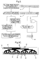
- Figure 2 is a flowchart showing a procedure to determine a value of a digital code;
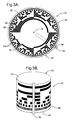
- Figure 3A is a top view of a disk as the coded element;
- Figure 3B is a perspective view of a cylinder as the coded element; and
- Figure 3C is a top view of a strip as the coded element utilizing a Gray code.
-
- Referring to the Figures, wherein like numerals indicate like parts throughout the several views, an assembly for sensing position is shown generally at 10 in Figure 1A.
- The
assembly 10 includes alight source 12 that supplies light. In the preferred embodiment, thelight source 12 is a light-emitting diode (LED) 14. Those skilled in the art will realize that other sources of light, including incandescent, fluorescent, or LASER sources could also be used. Preferably, alight guide 16 is used to evenly distribute the light provided by theLED 14. - The
assembly 10 also includes a codedelement 18 containing a plurality ofholes 20. The codedelement 18 is operatively connected to a movable object (not shown) whose position is to be measured. Examples of the movable object include, but are not limited to, a steering wheel of a vehicle, an arm of a robot, or a hand-operated control dial. The codedelement 18 also contains a plurality ofsolid portions 22. Theholes 20 andsolid portions 22 define digital codes that represent position of the movable object. It is preferred that the codedelement 18 also includesspacer portions 24 and anend portion 26, which are both solid. The light is transmitted through theholes 20 in the codedelement 18, as shown by dotted lines in Figure 1A. The light is blocked by thesolid portions 22,spacer portions 24, andend portion 26. - The
assembly 10 further includes a plurality ofphotosensors 28. Thephotosensors 28 receive the light either passed through theholes 20 or otherwise not blocked by the codedelement 18. Thephotosensors 28 provide electrical signals in response to the light. In the embodiments and examples illustrated herein, eachphotosensor 28 provides a high voltage signal (logical "1") when thephotosensor 28 is illuminated and a low voltage signal (logical "0") when thephotosensor 28 is not illuminated. However, those skilled in the art will recognized that thephotosensors 28 could work in the opposite manner, wherein anilluminated photosensor 28 provides a logical "0" and vice-versa. - The plurality of
photosensors 28 may be packaged in a linearoptical array 29. An example of asuitable array 29 is the MLX90255 manufactured by Melexis Microelectronic Systems of leper, Belgium, which includes 128usable photosensors 28. Another example of asuitable array 29 is the TSL218 manufactured by Texas Instruments Inc. of Dallas, Texas, which employs 512usable photosensors 28. Of course, many othersuitable arrays 29 can be substituted for those mentioned above. For purposes of simplicity in illustration, the linearoptical array 29 shown in Figures 1A and 1B utilize only thirty-twophotosensors 28. - The
holes 20 of the codedelement 18 are sized and thephotosensors 28 are positioned such that the light transmitted through each of theholes 20 illuminates more than onephotosensor 28. Thus, if contaminants build up on theholes 20 of the codedelement 18 to block the transmission of light, at least onephotosensor 28 will still be illuminated. - A first
binary register 44 is operatively connected to the plurality ofphotosensors 28 for storing bits generated by the electrical signals produced by the illumination of thephotosensors 28. The firstbinary register 44 may be packaged within the linearoptical array 29. - A
logic circuit 46 is operatively connected to the firstbinary register 44. Thelogic circuit 46 analyzes the firstbinary register 44 and determines a value of the digital code. A secondbinary register 48 is also operatively connected to thelogic circuit 46 for storing the value of the digital code. Preferably, thelogic circuit 46 and the secondbinary register 48 are packaged together in anintegrated circuit 50. Those skilled in the art will recognize that theintegrated circuit 50 may be a microprocessor, microcontroller, application specific integrated circuit (ASIC), etc. - Referring now to Figure 2, a procedure is implemented to determine the value of the digital code. The procedure begins by shifting the bits of the first
binary register 46. The bits are shifted until a start bit, illustrated by a first logical "0", is found. This first logical "0" represents anedge 25 of the codedelement 18 and the beginning of theend portion 26. Due to mechanical issues, the codedelement 18 may move from an original position as shown in Figure 1A, to a runnout position in Figure 1B. This change in position will not affect the procedure's ability to determine the value of the digital code, due to this first step of shifting bits until the first logical "0" representing theedge 25 of the codedelement 18 is found. Once the first logical "0" is found, the bits of the firstbinary register 46 are then shifted again to remove a known number of bits that correspond to a width of theend portion 26. - The procedure continues by examining a predetermined number of bits of the first
binary register 44 to determine a bit of the secondbinary register 48. This step can be performed by various techniques. In a first technique, a logical "OR" operation is performed on the predetermined number of bits. The result of the logical "OR" operation provides the bit of the secondbinary register 48. With a logical "OR" operation, if any of the predetermined number of bits is a logical "1", then the bit of the secondbinary register 48 will also be a logical "1". Only when all of the predetermined bits are logical "0"s, does the bit of the secondbinary register 48 become a logical "0". - A second technique involves determining a value of a majority of the predetermined number of bits. For example, if there are three predetermined number of bits, with two of them being logical "1"s and one being a logical "0", then the result is a logical "1". Obviously, this technique works best when the predetermined number is an odd number. However, a tie-breaker scheme could be implemented to allow the second technique to be implemented when the predetermined number of bits is even. Of course, additional techniques to examine the predetermined number of bits are contemplated by those skilled in the art.
- In the preferred embodiment, the coded
element 18 is adisk 30, as shown in Figure 3A. Thedisk 30 has acenter 32 and acircular edge 34. The plurality ofphotosensors 28 is positioned such that at least onephotosensor 28 is outside thecircular edge 34 of thedisk 30. This allows thephotosensors 28 to detect theedge 25 of the codedelement 18. The plurality ofphotosensors 28 extends from the outside of thecircular edge 34 toward thecenter 32 of thedisk 30. - Referring now to Figure 2B, in a first alternative embodiment, the coded
element 18 is acylinder 36. Thecylinder 36 has atop edge 40 and abottom edge 42. Again, the plurality ofphotosensors 28 is positioned such that at least onephotosensor 28 is outside thetop edge 40 of thecylinder 36. The plurality ofphotosensors 28 extend from outside thetop edge 40 toward thebottom edge 42. - In a second alternative embodiment, as shown in Figure 2C, a
strip 38 is the codedelement 18. Like thecylinder 36, thestrip 38 also includes atop edge 40 and abottom edge 42, and the plurality ofphotosensors 28 is positioned in a similar fashion. - The digital codes defined on the coded
element 18 may be implemented with error-reducing properties. For example, a Gray code may be used, as shown in Figure 2C. Gray codes are well known in the art and are described in United States Patent No. 2,632,058 to Frank Gray. - While the invention has been described with reference to an exemplary embodiment, it will be understood by those skilled in the art that various changes may be made and equivalents may be substituted for elements thereof without departing from the scope of the invention. In addition, many modifications may be made to adapt a particular situation or material to the teachings of the invention without departing from the essential scope thereof. Therefore, it is intended that the invention not be limited to the particular embodiment disclosed as the best mode contemplated for carrying out this invention, but that the invention will include all embodiments falling within the scope of the appended claims.
Claims (18)
- An assembly (10) for sensing position comprising:said holes (20) being sized and said photosensors (28) positioned relative to said holes (20) for transmitting said light to more than one of said photosensors (28) through each of said holes (20).a light source (12) for supplying light;a coded element (18) containing a plurality of holes (20) defining digital codes representing position;a plurality of photosensors (28) for receiving said light passed through said plurality of holes (20) representing one of said digital codes and providing electrical signals in response to said light;
- An assembly (10) as set forth in claim 1 further comprising a first binary register (44) operatively connected to said plurality of photosensors (28) for storing bits generated by said electrical signals.
- An assembly (10) as set forth in claim 2 further comprising a logic circuit (46) operatively connected to said first binary register (44) for determining a value of said digital code.
- An assembly (10) as set forth in claim 3 further comprising a second binary register (48) operatively connected to said logic circuit (46) for storing said value of said digital code.
- An assembly (10) as set forth in claim 1 further comprising a light guide (16) for evenly distributing said light.
- An assembly (10) as set forth in claim 1 wherein said coded element (18) is further defined as a disk (30) having a center (32) and a circular edge (34) with said plurality of photosensors (28) positioned between said circular edge (34) and said center (32).
- An assembly (10) as set forth in claim 1 wherein said coded element (18) is further defined as a cylinder (36) having a top edge (40) and a bottom edge (42) with said plurality of photosensors (28) positioned between said top edge (40) and said bottom edge (42).
- An assembly (10) as set forth in claim 1 wherein said coded element (18) is further defined as a strip (38) having a top edge (40) and a bottom edge (42) with said plurality of photosensors (28) positioned between said top edge (40) and said bottom edge (42).
- An assembly (10) as set forth in claim 1 wherein said light source (12) is further defined as a light emitting diode (14).
- An assembly (10) as set forth in claim 1 wherein said digital codes have error-correcting properties.
- An assembly (10) as set forth in claim 10 wherein said digital codes are Gray codes.
- A method of determining position comprising the steps of:transmitting light through holes (20) in a coded element (18) defining a plurality of digital codes representing position;sizing the holes (20) and positioning a plurality of photosensors (28) relative to the holes (20) to receive light with more than one photosensor (28) through each of the holes (20); andreceiving light through the holes (20) corresponding to one of the plurality of digital codes by the plurality of photosensors (28).
- A method as set forth in claim 12 further comprising the step of filling a first binary register (44) with bits corresponding to the illumination of the photosensors (28).
- A method as set forth in claim 13 further comprising the step of analyzing the bits of the first binary register (44) to determine a value of the digital code.
- A method as set forth in claim 14 wherein the step of analyzing the bits of the first binary register (44) comprises the step of shifting the bits until a start bit is found.
- A method as set forth in claim 15 wherein the step of analyzing the bits of the first binary register (44) further comprises the step of examining a predetermined number of bits of the first binary register (44) to determine a bit of a second binary register.
- A method as set forth in claim 16 wherein the step of examining a predetermined number of bits of the first binary register (44) is further defined as performing a logical "OR" operation on the predetermined number of bits.
- A method as set forth in claim 16 wherein the step of examining a predetermined number of bits of the first binary register (44) is further defined as determining a value of a majority of the predetermined number of bits.
Applications Claiming Priority (2)
| Application Number | Priority Date | Filing Date | Title |
|---|---|---|---|
| US10/794,954 US6927704B1 (en) | 2004-03-05 | 2004-03-05 | Fault tolerant optoelectronic position sensor |
| US794954 | 2004-03-05 |
Publications (1)
| Publication Number | Publication Date |
|---|---|
| EP1574824A1 true EP1574824A1 (en) | 2005-09-14 |
Family
ID=34808681
Family Applications (1)
| Application Number | Title | Priority Date | Filing Date |
|---|---|---|---|
| EP05075528A Withdrawn EP1574824A1 (en) | 2004-03-05 | 2005-03-03 | Fault tolerant optoelectronic position sensor |
Country Status (2)
| Country | Link |
|---|---|
| US (1) | US6927704B1 (en) |
| EP (1) | EP1574824A1 (en) |
Families Citing this family (6)
| Publication number | Priority date | Publication date | Assignee | Title |
|---|---|---|---|---|
| US7135673B2 (en) * | 2004-10-29 | 2006-11-14 | The Boeing Company | Imaging rotation angle absolute encoder |
| US7400269B2 (en) * | 2006-11-09 | 2008-07-15 | Avago Technologies Ecbu Ip Pte Ltd | Coding element with integrated limit switch |
| GB0906257D0 (en) | 2009-04-08 | 2009-05-20 | Renishaw Plc | Position encoder apparatus |
| GB0906258D0 (en) * | 2009-04-08 | 2009-05-20 | Renishaw Plc | Position encoder apparatus |
| US10859363B2 (en) | 2017-09-27 | 2020-12-08 | Stanley Black & Decker, Inc. | Tape rule assembly with linear optical encoder for sensing human-readable graduations of length |
| TWI680648B (en) * | 2018-12-26 | 2019-12-21 | 財團法人工業技術研究院 | Code disk, optical detector, optical absolute rotary encoder and method for outputting, error detecting and correcting code values |
Citations (4)
| Publication number | Priority date | Publication date | Assignee | Title |
|---|---|---|---|---|
| US4621256A (en) * | 1983-07-15 | 1986-11-04 | Lockheed Missiles & Space Company, Inc. | Apparatus for measuring rate of angular displacement |
| DE4202901A1 (en) * | 1992-02-01 | 1993-08-05 | Huebner Johannes | OPTICAL ABSOLUTE ANGLE SENSOR |
| EP0911610A1 (en) * | 1997-10-21 | 1999-04-28 | Eaton Corporation | Angle sensor using a multi-pixel optical device |
| US20030052262A1 (en) * | 2000-02-15 | 2003-03-20 | Frank Blasing | Coded disc for an optoelectronic displacement or angle measuring device |
Family Cites Families (13)
| Publication number | Priority date | Publication date | Assignee | Title |
|---|---|---|---|---|
| US4680466A (en) * | 1984-04-20 | 1987-07-14 | Yokogawa Hokushin Electric Corporation | Displacement transducer which simultaneously extracts signals via sequential switching |
| US4691101A (en) * | 1985-06-19 | 1987-09-01 | Hewlett-Packard Company | Optical positional encoder comprising immediately adjacent detectors |
| US4720699A (en) | 1985-10-28 | 1988-01-19 | Smith Ronald H | Optical encoder using line array detectors |
| JPS63262523A (en) | 1987-04-21 | 1988-10-28 | Matsushita Electric Ind Co Ltd | Absolute position detection method and device |
| DE4022837A1 (en) | 1990-07-18 | 1992-01-23 | Morche Dirk W Dipl Ing | Signal generator for motor vehicle steering angle - has disc with spiral slot rotating between linear light source and photoelectric receiver |
| US5173602A (en) | 1991-12-24 | 1992-12-22 | Xerox Corporation | Binary position sensitive detector with multiple rows of alternating types of photocells |
| SE501950C2 (en) | 1993-11-02 | 1995-06-26 | Leine & Linde Ab | Sensor unit method and sensor unit comprising a patterned code means |
| KR100378576B1 (en) * | 1994-08-25 | 2004-04-03 | 티알더블유 루카스베리티 일렉트릭 스티어링 리미티드 | Displacement sensor and torque sensor |
| US5825307A (en) | 1997-02-05 | 1998-10-20 | Perception Incorporated | Absolute linear encoder and method of production utilizing index and counter channels |
| TW411419B (en) * | 1997-10-09 | 2000-11-11 | Primax Electronics Ltd | Photo-grid system with positioning holes |
| US6100822A (en) * | 1998-03-02 | 2000-08-08 | Primax Electronics Ltd. | Optical sensing system using multiple detectors at various positions for generating position signals |
| DE19944004A1 (en) | 1999-09-14 | 2001-03-15 | Kostal Leopold Gmbh & Co Kg | Optoelectronic rotation angle sensor |
| DE19944005A1 (en) | 1999-09-14 | 2001-03-15 | Kostal Leopold Gmbh & Co Kg | Optoelectronic rotation angle sensor |
-
2004
- 2004-03-05 US US10/794,954 patent/US6927704B1/en not_active Expired - Fee Related
-
2005
- 2005-03-03 EP EP05075528A patent/EP1574824A1/en not_active Withdrawn
Patent Citations (4)
| Publication number | Priority date | Publication date | Assignee | Title |
|---|---|---|---|---|
| US4621256A (en) * | 1983-07-15 | 1986-11-04 | Lockheed Missiles & Space Company, Inc. | Apparatus for measuring rate of angular displacement |
| DE4202901A1 (en) * | 1992-02-01 | 1993-08-05 | Huebner Johannes | OPTICAL ABSOLUTE ANGLE SENSOR |
| EP0911610A1 (en) * | 1997-10-21 | 1999-04-28 | Eaton Corporation | Angle sensor using a multi-pixel optical device |
| US20030052262A1 (en) * | 2000-02-15 | 2003-03-20 | Frank Blasing | Coded disc for an optoelectronic displacement or angle measuring device |
Also Published As
| Publication number | Publication date |
|---|---|
| US6927704B1 (en) | 2005-08-09 |
Similar Documents
| Publication | Publication Date | Title |
|---|---|---|
| JP5424629B2 (en) | Position measuring apparatus and method for measuring absolute position | |
| US5539993A (en) | Location scale and optical reading sensor for reading the location scale | |
| EP0503716A1 (en) | Measuring device for determining an absolute position of a movable element and scale graduation element suitable for use in such a measuring device | |
| CN1975340B (en) | Optical encoder with sinusoidal photodetector output signal | |
| KR101962475B1 (en) | Linear position measuring system | |
| US20070186431A1 (en) | Position measuring arrangement | |
| US7013575B2 (en) | Position measuring device | |
| US7394061B2 (en) | Optical encoder with integrated index channel | |
| US7835014B2 (en) | Position measuring arrangement | |
| US8742956B2 (en) | Position encoder apparatus | |
| JP2001526401A (en) | Adaptive steering absolute angle sensor | |
| US6927704B1 (en) | Fault tolerant optoelectronic position sensor | |
| US20080257951A1 (en) | Position-measuring device | |
| GB2353421A (en) | Determining the position between two parts which move relative to each other | |
| US7348545B2 (en) | System and method for optical encoding on two opposed surfaces of a pattern medium | |
| CN102209882B (en) | Optical coder | |
| US7400269B2 (en) | Coding element with integrated limit switch | |
| US20090206244A1 (en) | Single Track Optical Encoder | |
| US10014932B2 (en) | Method and apparatus for determining a signal transmission quality of a light transmission path | |
| US6693565B2 (en) | Position transducer | |
| US7521669B2 (en) | Multi-bit absolute position optical encoder with reduced number of tracks | |
| US7397394B2 (en) | Process to determine the absolute angular position of a motor vehicle steering wheel | |
| KR101742319B1 (en) | Scanning unit of a position measuring device | |
| EP1480012A2 (en) | Position encoder | |
| US7638756B2 (en) | Photodetector array and codewheel configuration for flexible optical encoder resolution |
Legal Events
| Date | Code | Title | Description |
|---|---|---|---|
| PUAI | Public reference made under article 153(3) epc to a published international application that has entered the european phase |
Free format text: ORIGINAL CODE: 0009012 |
|
| AK | Designated contracting states |
Kind code of ref document: A1 Designated state(s): AT BE BG CH CY CZ DE DK EE ES FI FR GB GR HU IE IS IT LI LT LU MC NL PL PT RO SE SI SK TR |
|
| AX | Request for extension of the european patent |
Extension state: AL BA HR LV MK YU |
|
| 17P | Request for examination filed |
Effective date: 20060314 |
|
| AKX | Designation fees paid |
Designated state(s): AT BE BG CH CY CZ DE DK EE ES FI FR GB GR HU IE IS IT LI LT LU MC NL PL PT RO SE SI SK TR |
|
| RAP1 | Party data changed (applicant data changed or rights of an application transferred) |
Owner name: GM GLOBAL TECHNOLOGY OPERATIONS, INC. |
|
| RAP1 | Party data changed (applicant data changed or rights of an application transferred) |
Owner name: GM GLOBAL TECHNOLOGY OPERATIONS LLC |
|
| RAP1 | Party data changed (applicant data changed or rights of an application transferred) |
Owner name: STEERING SOLUTIONS IP HOLDING CORPORATION Owner name: GM GLOBAL TECHNOLOGY OPERATIONS LLC |
|
| STAA | Information on the status of an ep patent application or granted ep patent |
Free format text: STATUS: THE APPLICATION IS DEEMED TO BE WITHDRAWN |
|
| 18D | Application deemed to be withdrawn |
Effective date: 20131001 |