EP1574733A1 - Method of manufacturing friction plate for wet clutch - Google Patents
Method of manufacturing friction plate for wet clutch Download PDFInfo
- Publication number
- EP1574733A1 EP1574733A1 EP04251432A EP04251432A EP1574733A1 EP 1574733 A1 EP1574733 A1 EP 1574733A1 EP 04251432 A EP04251432 A EP 04251432A EP 04251432 A EP04251432 A EP 04251432A EP 1574733 A1 EP1574733 A1 EP 1574733A1
- Authority
- EP
- European Patent Office
- Prior art keywords
- friction member
- strips
- core plate
- segments
- friction
- Prior art date
- Legal status (The legal status is an assumption and is not a legal conclusion. Google has not performed a legal analysis and makes no representation as to the accuracy of the status listed.)
- Granted
Links
Images







Classifications
-
- F—MECHANICAL ENGINEERING; LIGHTING; HEATING; WEAPONS; BLASTING
- F16—ENGINEERING ELEMENTS AND UNITS; GENERAL MEASURES FOR PRODUCING AND MAINTAINING EFFECTIVE FUNCTIONING OF MACHINES OR INSTALLATIONS; THERMAL INSULATION IN GENERAL
- F16D—COUPLINGS FOR TRANSMITTING ROTATION; CLUTCHES; BRAKES
- F16D69/00—Friction linings; Attachment thereof; Selection of coacting friction substances or surfaces
- F16D69/04—Attachment of linings
-
- F—MECHANICAL ENGINEERING; LIGHTING; HEATING; WEAPONS; BLASTING
- F16—ENGINEERING ELEMENTS AND UNITS; GENERAL MEASURES FOR PRODUCING AND MAINTAINING EFFECTIVE FUNCTIONING OF MACHINES OR INSTALLATIONS; THERMAL INSULATION IN GENERAL
- F16D—COUPLINGS FOR TRANSMITTING ROTATION; CLUTCHES; BRAKES
- F16D13/00—Friction clutches
- F16D13/58—Details
- F16D13/60—Clutching elements
- F16D13/64—Clutch-plates; Clutch-lamellae
- F16D13/648—Clutch-plates; Clutch-lamellae for clutches with multiple lamellae
-
- F—MECHANICAL ENGINEERING; LIGHTING; HEATING; WEAPONS; BLASTING
- F16—ENGINEERING ELEMENTS AND UNITS; GENERAL MEASURES FOR PRODUCING AND MAINTAINING EFFECTIVE FUNCTIONING OF MACHINES OR INSTALLATIONS; THERMAL INSULATION IN GENERAL
- F16D—COUPLINGS FOR TRANSMITTING ROTATION; CLUTCHES; BRAKES
- F16D69/00—Friction linings; Attachment thereof; Selection of coacting friction substances or surfaces
- F16D2069/004—Profiled friction surfaces, e.g. grooves, dimples
-
- F—MECHANICAL ENGINEERING; LIGHTING; HEATING; WEAPONS; BLASTING
- F16—ENGINEERING ELEMENTS AND UNITS; GENERAL MEASURES FOR PRODUCING AND MAINTAINING EFFECTIVE FUNCTIONING OF MACHINES OR INSTALLATIONS; THERMAL INSULATION IN GENERAL
- F16D—COUPLINGS FOR TRANSMITTING ROTATION; CLUTCHES; BRAKES
- F16D69/00—Friction linings; Attachment thereof; Selection of coacting friction substances or surfaces
- F16D69/04—Attachment of linings
- F16D2069/0425—Attachment methods or devices
- F16D2069/045—Bonding
-
- F—MECHANICAL ENGINEERING; LIGHTING; HEATING; WEAPONS; BLASTING
- F16—ENGINEERING ELEMENTS AND UNITS; GENERAL MEASURES FOR PRODUCING AND MAINTAINING EFFECTIVE FUNCTIONING OF MACHINES OR INSTALLATIONS; THERMAL INSULATION IN GENERAL
- F16D—COUPLINGS FOR TRANSMITTING ROTATION; CLUTCHES; BRAKES
- F16D69/00—Friction linings; Attachment thereof; Selection of coacting friction substances or surfaces
- F16D69/04—Attachment of linings
- F16D2069/0425—Attachment methods or devices
- F16D2069/0491—Tools, machines, processes
Definitions
- the present invention relates to a method of manufacturing a friction plate for a wet clutch.
- friction plate including an annular core plate and friction members bonded to opposite annular flat surfaces of the annular core plate, each friction member comprising a plurality of friction member segments disposed on the annular flat surface, an oil groove being provided between adjacent friction member segments.
- a method which includes steps of subjecting a band-shaped friction member material to a punching treatment to form friction member segments and bonding the friction member segments one by one to the annular flat surface (for example, see Japanese Patent Application Laid-open Nos. 7-151175 and 6-300051).
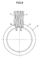
- a method of manufacturing a friction plate for a wet clutch which includes an annular core plate and a friction member bonded to at least one of annular flat surfaces of the annular core plate, each friction member comprising a plurality of friction member segments disposed on the annular flat surface, an oil groove being provided between adjacent friction member segments, wherein the following steps are adopted to bond the plurality of friction member segments simultaneously to the annular flat surface of the annular core plate: a step of making a plurality of cuts in at least one band-shaped friction member material in a lengthwise direction to form a plurality of friction member strips; a step of retaining the friction member strips with distances corresponding to the oil grooves being formed between adjacent friction member strips; a step of cutting off a portion of a tip end of at least one of the friction member strips which are located at opposite ends to thereby secure the oil grooves between the friction member segments on the annular flat surface; and a step of superposing friction member segment correspondence portions forming the tip ends of the plurality of
- the cutting for forming the friction member strips, the cutting-off for securing the oil grooves and the cutting-away of the friction member segment correspondence portions from the remaining portions of the friction member strips can be carried out using cutting edges, respectively.
- scraps produced can be limited to those produced by the cutting-off, to thereby increase the yield in the fabrication of the friction member segments.
- each of the oil grooves can be changed freely by changing the distance between the adjacent friction member strips, and the shapes of the oil grooves can be also changed by changing the shapes of the cuts in the formation of the friction member strips. Moreover, the plurality of friction member segments are bonded simultaneously to the core plate, which is effective for improving the productivity for the friction plate.
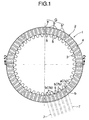
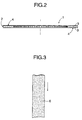
- a friction plate 1 for a wet clutch includes an annular core plate 2 made of a metal, and a friction member 4 formed from a fiber component, an additional component, a binder and the like and bonded to at least one annular flat surface 3 of the annular core plate 2, e.g., to opposite annular flat surfaces 3 in the present embodiment.
- Each of the friction members 4 comprises a plurality of friction member segments disposed on the annular flat surface 3.
- each of the friction members 4 comprises ten sets of segment groups G, each of which comprises a single triangular friction member segment a and five rectangular friction member segments b arranged in a clockwise direction in Fig.1 from the segment a.
- An oil groove 5 is provided between the adjacent friction member segments a and b or b and b.
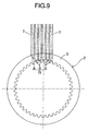
- each of the friction members 4 the plurality of friction member segments a and b , namely, the segments of one group G are bonded simultaneously to the one annular flat surface 3 of the annular core plate 2, and the same bonding operation is then repeated nine times.
- the produced scraps 10 can be limited to those produced by the cutting-off in fabrication of the friction member segments a and b from the band-shaped friction member material 6, whereby the yield in the fabrication of the friction member segments a and b can be increased.
- the width (the circumferential length) of each of five rectangular friction member segments b in each of segment groups G is larger at a location more apart from the triangular friction member segment a. This is achieved by changing the width of the friction member strip 7.
- the width (circumferential length) of an oil groove 5 between a triangular friction member segment a and a rectangular friction member segment b adjacent thereto in each of segment groups G is smallest, and the width of each of the other grooves 5 is larger at a location more apart from the triangular friction member segment a . This is achieved by changing the distance between the adjacent friction member strips 7.
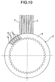
- two friction member strips 7 are used, and a portion of each of tip ends of the friction member strips 7, namely, an outer corner is cut off to secure an oil groove 5, whereby two triangular scraps 10 are produced.
- two friction member segment correspondence portions 7b form two rectangular friction member segments b , which form one segment group G.
- the two friction member strips 7 correspond to ones at opposite ends in the plurality of strip-shaped frictions.
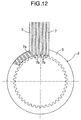
- a friction member 4 is divided into an outer peripheral half 4A and an inner peripheral half 4B.
- the formation of the outer peripheral half 4A is carried out using two friction member strips 7, and the formation of the inner peripheral half 4B is carried out using two friction member strips 7.
- a portion of a tip end of each of the friction member strips 7 is cut off to secure an oil groove 5, as in the embodiment shown in Fig. 16.
- the above-described cutting-off and the cutting-away of each friction member segment correspondence portions 7b in the formation of the inner peripheral half 4B are carried out on the core plate 2 using the cutting edge.
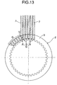
- one segment group G comprises a single triangular friction member segment a, two deformed friction member segments c having one side curved in an S-shape, and three S-shaped deformed friction member segments d.
- 7c and 7d are friction member segment correspondence portions.
- each of deformed friction member segments e excluding a triangular friction member segment a is formed into an arrow-feather-shape, so that a face turned radially inwards is a V-shaped concave face 11, and a face turned radially outwards is a V-shaped convex face 12.
- the deformed friction member segments e each having the arrow-feather-shape obstruct the discharge of the oil and hence, the drag of the clutch is reduced.
- 7e is a friction member segment correspondence portion.
- a friction plate 1 is demanded, for example, in a wet clutch disclosed in Japanese Patent Application Laid-open No. 2-3716.
- 14f designates a friction member segment correspondence portion.
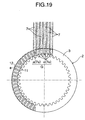
- FIG. 21 An embodiment shown in Fig. 21 corresponds to a modification of the embodiments shown in Fig. 1 to 13. More specifically, six friction member strips 7 constitute one assembly A. Friction member segment correspondence portions 7a and 7b in ten assemblies A are equally disposed on one of annular flat surfaces 3 of a core plate 2, and ten segment groups G are bonded simultaneously. Therefore, a friction member 4 on one side is formed by one run of a bonding operation. If such a means is adopted, the accuracy of the positions of the segment groups G can be enhanced easily.
- the friction plate 1 may be a friction plate including a friction member 4 on only one of annular flat surfaces 3 of a core plate 2.
Landscapes
- Engineering & Computer Science (AREA)
- General Engineering & Computer Science (AREA)
- Mechanical Engineering (AREA)
- Mechanical Operated Clutches (AREA)
- Braking Arrangements (AREA)
Abstract
Description
An
Claims (1)
- A method of manufacturing a friction plate (1) for a wet clutch which includes an annular core plate (2) and a friction member (4) bonded to at least one of annular flat surfaces (3) of the annular core plate, each friction member comprising a plurality of friction member segments (a,b) disposed on the annular flat surface, an oil groove (5) being provided between adjacent friction member segments,
wherein the following steps are adopted to bond the plurality of friction member segments simultaneously to the annular flat surface of the annular core plate: a step of making a plurality of cuts in at least one band-shaped friction member material (6) in a lengthwise direction to form a plurality of friction member strips (7); a step of retaining the friction member strips with distances corresponding to the oil grooves being formed between adjacent friction member strips; a step of cutting off a portion of a tip end of at least one of the friction member strips which are located at opposite ends to thereby secure the oil grooves between the friction member segments on the annular flat surface; and a step of superposing friction member segment correspondence portions forming the tip ends of the plurality of friction member strips to the annular flat surface of the core plate having an adhesive applied thereto, and cutting the friction member segment correspondence portions away from the remaining portions of the friction member strips.
Priority Applications (1)
| Application Number | Priority Date | Filing Date | Title |
|---|---|---|---|
| EP04251432A EP1574733B1 (en) | 2004-03-12 | 2004-03-12 | Method of manufacturing friction plate for wet clutch |
Applications Claiming Priority (1)
| Application Number | Priority Date | Filing Date | Title |
|---|---|---|---|
| EP04251432A EP1574733B1 (en) | 2004-03-12 | 2004-03-12 | Method of manufacturing friction plate for wet clutch |
Publications (2)
| Publication Number | Publication Date |
|---|---|
| EP1574733A1 true EP1574733A1 (en) | 2005-09-14 |
| EP1574733B1 EP1574733B1 (en) | 2008-01-16 |
Family
ID=34814412
Family Applications (1)
| Application Number | Title | Priority Date | Filing Date |
|---|---|---|---|
| EP04251432A Expired - Lifetime EP1574733B1 (en) | 2004-03-12 | 2004-03-12 | Method of manufacturing friction plate for wet clutch |
Country Status (1)
| Country | Link |
|---|---|
| EP (1) | EP1574733B1 (en) |
Cited By (1)
| Publication number | Priority date | Publication date | Assignee | Title |
|---|---|---|---|---|
| EP1548312A3 (en) * | 2003-12-22 | 2006-04-26 | Kabushiki Kaisha F.C.C. | Process and device for producing clutch friction plate |
Citations (4)
| Publication number | Priority date | Publication date | Assignee | Title |
|---|---|---|---|---|
| US4260047A (en) * | 1979-12-03 | 1981-04-07 | General Motors Corporation | Friction disc and method of making same |
| US4878282A (en) * | 1987-09-04 | 1989-11-07 | Borg-Warner Automotive Gmbh | Method for the production of friction plates, synchronizing blocker rings or similar structures |
| US5454454A (en) * | 1993-11-22 | 1995-10-03 | Raybestos Products Co. | Polygonal friction disk and method |
| EP0806586A2 (en) * | 1996-05-07 | 1997-11-12 | Advanced Friction Materials Company | A lined clutch plate and a method of producing a lined clutch plate |
Family Cites Families (1)
| Publication number | Priority date | Publication date | Assignee | Title |
|---|---|---|---|---|
| JP3971745B2 (en) * | 2003-12-22 | 2007-09-05 | 株式会社エフ・シー・シー | Method and apparatus for manufacturing clutch friction plate |
-
2004
- 2004-03-12 EP EP04251432A patent/EP1574733B1/en not_active Expired - Lifetime
Patent Citations (4)
| Publication number | Priority date | Publication date | Assignee | Title |
|---|---|---|---|---|
| US4260047A (en) * | 1979-12-03 | 1981-04-07 | General Motors Corporation | Friction disc and method of making same |
| US4878282A (en) * | 1987-09-04 | 1989-11-07 | Borg-Warner Automotive Gmbh | Method for the production of friction plates, synchronizing blocker rings or similar structures |
| US5454454A (en) * | 1993-11-22 | 1995-10-03 | Raybestos Products Co. | Polygonal friction disk and method |
| EP0806586A2 (en) * | 1996-05-07 | 1997-11-12 | Advanced Friction Materials Company | A lined clutch plate and a method of producing a lined clutch plate |
Cited By (3)
| Publication number | Priority date | Publication date | Assignee | Title |
|---|---|---|---|---|
| EP1548312A3 (en) * | 2003-12-22 | 2006-04-26 | Kabushiki Kaisha F.C.C. | Process and device for producing clutch friction plate |
| US7240413B2 (en) | 2003-12-22 | 2007-07-10 | Kabushiki Kaisha F.C.C. | Process and device for producing clutch friction plate |
| US7434300B2 (en) | 2003-12-22 | 2008-10-14 | Kabushiki Kaisha F.C.C. | Process and device for producing clutch friction plate |
Also Published As
| Publication number | Publication date |
|---|---|
| EP1574733B1 (en) | 2008-01-16 |
Similar Documents
| Publication | Publication Date | Title |
|---|---|---|
| US6899783B2 (en) | Method of manufacturing friction plate for wet clutch | |
| CN101523696B (en) | Laminated iron core and manufacturing method thereof | |
| EP2187502B1 (en) | Laminated core and method for manufacturing the same | |
| JP3676192B2 (en) | Punching method for continuously variable transmission belt elements | |
| CN103329409A (en) | Method of manufacturing laminated stator core and laminated stator core manufactured by the method | |
| JP5399290B2 (en) | Laser machine optical path bellows | |
| JP2008303950A (en) | Transmission belt | |
| JP6934714B2 (en) | Manufacturing method of laminated iron core and laminated iron core | |
| CA2460681C (en) | Method of manufacturing friction plate for wet clutch | |
| EP1574733B1 (en) | Method of manufacturing friction plate for wet clutch | |
| JP5186467B2 (en) | Rotating electric machine stator core | |
| CN1134861A (en) | Method for steelplate punching processing | |
| JP4611272B2 (en) | Laminated iron core and method for manufacturing the same | |
| JP5462643B2 (en) | Laminated iron core and method for manufacturing the same | |
| JP4523616B2 (en) | Friction plate for wet clutch and manufacturing method thereof | |
| US6325186B1 (en) | Near-net shape fabrication of friction disk ring structures | |
| JP2859567B2 (en) | Wet friction material | |
| WO2020261709A1 (en) | Tape | |
| JP4868346B2 (en) | Cutter roller, method for producing long film with cut and method for producing bag with cut | |
| JP4282824B2 (en) | Wet friction engagement plate and manufacturing method thereof | |
| WO2024004437A1 (en) | Method for manufacturing laminated iron core and laminated iron core | |
| US11754146B2 (en) | Belt element for vehicular transmission belt | |
| CN118174503A (en) | Stator core processing method, stator core, motor, compressor and vehicle | |
| JP2006029498A (en) | Brake shoe manufacturing method | |
| JPS6280316A (en) | Clutch facing device |
Legal Events
| Date | Code | Title | Description |
|---|---|---|---|
| PUAI | Public reference made under article 153(3) epc to a published international application that has entered the european phase |
Free format text: ORIGINAL CODE: 0009012 |
|
| 17P | Request for examination filed |
Effective date: 20041028 |
|
| AK | Designated contracting states |
Kind code of ref document: A1 Designated state(s): AT BE BG CH CY CZ DE DK EE ES FI FR GB GR HU IE IT LI LU MC NL PL PT RO SE SI SK TR |
|
| AX | Request for extension of the european patent |
Extension state: AL LT LV MK |
|
| AKX | Designation fees paid |
Designated state(s): BE FR GB IT |
|
| REG | Reference to a national code |
Ref country code: DE Ref legal event code: 8566 |
|
| 17Q | First examination report despatched |
Effective date: 20061031 |
|
| GRAP | Despatch of communication of intention to grant a patent |
Free format text: ORIGINAL CODE: EPIDOSNIGR1 |
|
| RIN1 | Information on inventor provided before grant (corrected) |
Inventor name: OGURI, KENSUKE,C/O KABUSHIKI KAISHA F.C.C. Inventor name: TSUBOI, TSUTOMU,C/O KABUSHIKI KAISHA F.C.C. |
|
| GRAS | Grant fee paid |
Free format text: ORIGINAL CODE: EPIDOSNIGR3 |
|
| GRAA | (expected) grant |
Free format text: ORIGINAL CODE: 0009210 |
|
| AK | Designated contracting states |
Kind code of ref document: B1 Designated state(s): BE FR GB IT |
|
| REG | Reference to a national code |
Ref country code: GB Ref legal event code: FG4D |
|
| PGFP | Annual fee paid to national office [announced via postgrant information from national office to epo] |
Ref country code: GB Payment date: 20080229 Year of fee payment: 5 |
|
| PGFP | Annual fee paid to national office [announced via postgrant information from national office to epo] |
Ref country code: BE Payment date: 20080416 Year of fee payment: 5 |
|
| PLBE | No opposition filed within time limit |
Free format text: ORIGINAL CODE: 0009261 |
|
| STAA | Information on the status of an ep patent application or granted ep patent |
Free format text: STATUS: NO OPPOSITION FILED WITHIN TIME LIMIT |
|
| 26N | No opposition filed |
Effective date: 20081017 |
|
| BERE | Be: lapsed |
Owner name: K.K. F.C.C. Effective date: 20090331 |
|
| GBPC | Gb: european patent ceased through non-payment of renewal fee |
Effective date: 20090312 |
|
| PG25 | Lapsed in a contracting state [announced via postgrant information from national office to epo] |
Ref country code: BE Free format text: LAPSE BECAUSE OF NON-PAYMENT OF DUE FEES Effective date: 20090331 |
|
| PG25 | Lapsed in a contracting state [announced via postgrant information from national office to epo] |
Ref country code: GB Free format text: LAPSE BECAUSE OF NON-PAYMENT OF DUE FEES Effective date: 20090312 |
|
| REG | Reference to a national code |
Ref country code: FR Ref legal event code: PLFP Year of fee payment: 13 |
|
| REG | Reference to a national code |
Ref country code: FR Ref legal event code: PLFP Year of fee payment: 14 |
|
| REG | Reference to a national code |
Ref country code: FR Ref legal event code: PLFP Year of fee payment: 15 |
|
| PGFP | Annual fee paid to national office [announced via postgrant information from national office to epo] |
Ref country code: IT Payment date: 20200221 Year of fee payment: 17 |
|
| PGFP | Annual fee paid to national office [announced via postgrant information from national office to epo] |
Ref country code: FR Payment date: 20200214 Year of fee payment: 17 |
|
| PG25 | Lapsed in a contracting state [announced via postgrant information from national office to epo] |
Ref country code: FR Free format text: LAPSE BECAUSE OF NON-PAYMENT OF DUE FEES Effective date: 20210331 |
|
| PG25 | Lapsed in a contracting state [announced via postgrant information from national office to epo] |
Ref country code: IT Free format text: LAPSE BECAUSE OF NON-PAYMENT OF DUE FEES Effective date: 20210312 |