EP1574687A1 - Mechanical drive system for an accessory gearbox - Google Patents
Mechanical drive system for an accessory gearbox Download PDFInfo
- Publication number
- EP1574687A1 EP1574687A1 EP05251095A EP05251095A EP1574687A1 EP 1574687 A1 EP1574687 A1 EP 1574687A1 EP 05251095 A EP05251095 A EP 05251095A EP 05251095 A EP05251095 A EP 05251095A EP 1574687 A1 EP1574687 A1 EP 1574687A1
- Authority
- EP
- European Patent Office
- Prior art keywords
- shaft
- gear
- tower
- bevel gear
- pressure
- Prior art date
- Legal status (The legal status is an assumption and is not a legal conclusion. Google has not performed a legal analysis and makes no representation as to the accuracy of the status listed.)
- Withdrawn
Links
- 230000001154 acute effect Effects 0.000 description 1
- 230000008878 coupling Effects 0.000 description 1
- 238000010168 coupling process Methods 0.000 description 1
- 238000005859 coupling reaction Methods 0.000 description 1
- 239000000446 fuel Substances 0.000 description 1
Images


Classifications
-
- F—MECHANICAL ENGINEERING; LIGHTING; HEATING; WEAPONS; BLASTING
- F02—COMBUSTION ENGINES; HOT-GAS OR COMBUSTION-PRODUCT ENGINE PLANTS
- F02C—GAS-TURBINE PLANTS; AIR INTAKES FOR JET-PROPULSION PLANTS; CONTROLLING FUEL SUPPLY IN AIR-BREATHING JET-PROPULSION PLANTS
- F02C7/00—Features, components parts, details or accessories, not provided for in, or of interest apart form groups F02C1/00 - F02C6/00; Air intakes for jet-propulsion plants
- F02C7/32—Arrangement, mounting, or driving, of auxiliaries
-
- F—MECHANICAL ENGINEERING; LIGHTING; HEATING; WEAPONS; BLASTING
- F02—COMBUSTION ENGINES; HOT-GAS OR COMBUSTION-PRODUCT ENGINE PLANTS
- F02C—GAS-TURBINE PLANTS; AIR INTAKES FOR JET-PROPULSION PLANTS; CONTROLLING FUEL SUPPLY IN AIR-BREATHING JET-PROPULSION PLANTS
- F02C7/00—Features, components parts, details or accessories, not provided for in, or of interest apart form groups F02C1/00 - F02C6/00; Air intakes for jet-propulsion plants
- F02C7/36—Power transmission arrangements between the different shafts of the gas turbine plant, or between the gas-turbine plant and the power user
-
- F—MECHANICAL ENGINEERING; LIGHTING; HEATING; WEAPONS; BLASTING
- F05—INDEXING SCHEMES RELATING TO ENGINES OR PUMPS IN VARIOUS SUBCLASSES OF CLASSES F01-F04
- F05D—INDEXING SCHEME FOR ASPECTS RELATING TO NON-POSITIVE-DISPLACEMENT MACHINES OR ENGINES, GAS-TURBINES OR JET-PROPULSION PLANTS
- F05D2260/00—Function
- F05D2260/40—Transmission of power
- F05D2260/403—Transmission of power through the shape of the drive components
- F05D2260/4031—Transmission of power through the shape of the drive components as in toothed gearing
-
- F—MECHANICAL ENGINEERING; LIGHTING; HEATING; WEAPONS; BLASTING
- F05—INDEXING SCHEMES RELATING TO ENGINES OR PUMPS IN VARIOUS SUBCLASSES OF CLASSES F01-F04
- F05D—INDEXING SCHEME FOR ASPECTS RELATING TO NON-POSITIVE-DISPLACEMENT MACHINES OR ENGINES, GAS-TURBINES OR JET-PROPULSION PLANTS
- F05D2260/00—Function
- F05D2260/50—Kinematic linkage, i.e. transmission of position
- F05D2260/53—Kinematic linkage, i.e. transmission of position using gears
-
- Y—GENERAL TAGGING OF NEW TECHNOLOGICAL DEVELOPMENTS; GENERAL TAGGING OF CROSS-SECTIONAL TECHNOLOGIES SPANNING OVER SEVERAL SECTIONS OF THE IPC; TECHNICAL SUBJECTS COVERED BY FORMER USPC CROSS-REFERENCE ART COLLECTIONS [XRACs] AND DIGESTS
- Y10—TECHNICAL SUBJECTS COVERED BY FORMER USPC
- Y10T—TECHNICAL SUBJECTS COVERED BY FORMER US CLASSIFICATION
- Y10T74/00—Machine element or mechanism
- Y10T74/19—Gearing
- Y10T74/19023—Plural power paths to and/or from gearing
- Y10T74/19074—Single drive plural driven
- Y10T74/19079—Parallel
- Y10T74/19084—Spur
Definitions
- the present invention relates to gas turbine engines in general, and to apparatus for driving an accessory gearbox in particular.
- Aircraft powered by gas turbine engines very often include a mechanically driven accessory gearbox for driving accessory systems such as fuel pumps, scavenge pumps, electrical generators, hydraulic pumps, etc.
- the power requirements of the accessory gearbox continue to increase as the number of electrical systems within the aircraft increase.
- the accessory gearbox has been driven by a mechanical system connected to the drive shaft (i.e., the "high pressure drive shaft") extending between the high-pressure turbine and the high-pressure compressor of the gas turbine engine.
- the ability to tap power off of the high-pressure drive shaft is limited, however. What is needed is an apparatus for mechanically driving an accessory gearbox that can accommodate the higher power requirements of modern aircraft.
- a mechanical drive system for an accessory gearbox of a gas turbine engine has a high-pressure drive shaft and a low-pressure drive shaft.
- the mechanical drive system includes a first tower shaft, a second tower shaft, a first lay shaft, and a second lay shaft.
- the first tower shaft is driven by the high-pressure drive shaft.
- the second tower shaft is driven by the low-pressure drive shaft.
- the tower shafts drive the accessory gearbox.
- One of the advantages of the present invention mechanical drive system for an accessory gearbox is that it provides increased versatility and capability over prior art mechanical drive systems that utilize a single tower shaft engaged with the high-pressure drive shaft.
- the present invention has the capacity to draw power off of the low-pressure drive shaft and the high-pressure shaft alternatively, or at the same time.
- a gas turbine engine 10 is diagrammatically shown.
- the engine includes a high-pressure drive shaft 12, a low-pressure drive shaft 14, a low-pressure compressor 16, a high-pressure compressor 18, a high-pressure turbine 20, a low-pressure turbine 22, an accessory gearbox 24, and a mechanical drive system 26 for the accessory gearbox 24.
- the drive shafts 12,14, compressor sections 16,18, and turbine sections 20,22 are centered about an axially extending engine centerline 28.
- the low-pressure compressor 16 is disposed axially forward of the high-pressure compressor 18, and the high pressure turbine 20 is positioned forward of the low-pressure turbine 22.
- the term forward is used to indicate position along the axially extending engine centerline.
- a first component "forward" of a second component is positioned closer to the inlet 30 of the engine 10.
- the second component is positioned "aft" of the first component. In most instances, gas flow traveling through the core of the engine 10 encounters the forward component before it encounters the aft component.
- the low-pressure and high-pressure compressor sections 16,18 and the high and low-pressure turbine sections 20,22 each includes a plurality of stator and rotor stages.
- the high-pressure drive shaft 12 is connected to and extends between the high-pressure compressor 18 and the high-pressure turbine 20.
- the low-pressure drive shaft 14 is connected to and extends between the low-pressure compressor 16 and the low-pressure turbine 22.
- the high-pressure drive shaft 12 and the low-pressure drive shaft 14 rotate about the axially extending engine centerline 28.
- the drive shafts 12,14 are diagrammatically shown in FIG.1 as concentric cylinders to simply illustrate the relationship between the components. Most low-pressure and high-pressure drive shafts are concentric, but have relatively complex geometries to accommodate all of the various components attached thereto and disposed adjacent thereto.
- the portions of the drive shafts 12,14 shown in FIG.2 is illustrated with geometries more typical of those actually used within gas turbine engines.
- the mechanical drive system 26 for the accessory gearbox 24 includes a low-pressure drive shaft gear arrangement 32 ("LPDS gear arrangement”), a high-pressure drive shaft gear arrangement 34 ("HPDS gear arrangement”), a first tower shaft 36, a second tower shaft 38, a first angle gear arrangement 40, a second angle gear arrangement 42, a first lay shaft 44, and a second lay shaft 46.
- the LPDS gear arrangement 32 includes a first spur gear 43, a second spur gear 45, an intermediate shaft 47, a first bevel gear 48, and a second bevel gear 50.
- the first spur gear is fixed (e.g., by one or more splines) to the low-pressure drive shaft 14.
- the second spur gear 45 and the first bevel gear 48 are attached to the intermediate shaft 47.
- the second spur gear 45 is engaged with the first spur gear 43.
- the first bevel gear 48 is engaged with the second bevel gear 50, which is fixed to the second tower shaft 38.
- the HPDS gear arrangement 34 includes a third bevel gear 52 and a fourth bevel gear 54.
- the third bevel gear 52 is fixed (e.g., by one or more splines) to the high-pressure drive shaft 12.
- the third bevel gear 52 is engaged with the fourth bevel gear 54, which is fixed to the first tower shaft 36.
- the first and second tower shafts 36,38 are concentrically arranged and rotatable about a lengthwise extending axis 56.
- the axis 56 is typically oriented perpendicular to (or at an acute angle therefrom) the engine centerline 28.
- the second tower shaft 38 is disposed radially outside of the first tower shaft 36 for substantially all of the portions in which the two tower shafts 36,38 are concentric.
- the first and second tower shafts 36,38 typically each include one or more bearing mounts 58 to positionally locate and to facilitate rotation of the respective tower shaft 36,38.
- Each tower shaft 36,38 may be a unitary shaft or it may include multiple sections connected together (e.g., by splines, etc.).
- the first and second angle gear arrangements 40,42 are configured for use with concentric tower shafts 36,38 and concentric lay shafts 44,46.
- the first angle gear arrangement 40 includes a fifth bevel gear 60 and a sixth bevel gear 62
- the second angle gear arrangement 42 includes a seventh bevel gear 64 and an eighth bevel gear 66.
- the fifth bevel gear 60 is attached to the first tower shaft 36, and is engaged with the sixth bevel gear 62, which is attached to the first lay shaft 44.
- the seventh bevel gear 64 is attached to the second tower shaft 38, and is engaged with the eighth bevel gear 66, which is attached to the second lay shaft 46.
- first and second lay shafts 44,46 are concentrically arranged and rotatable about a lengthwise extending axis 68.
- the first lay shaft 44 is disposed radially inside of the second lay shaft 46 for substantially all of the portions in which the two lay shafts 44,46 are concentric.
- the first and second lay shafts 44,46 each typically include one or more bearing mounts 70 to positionally locate and to facilitate rotation of the respective lay shaft 44,46.
- Each lay shaft 44,46 may be a unitary shaft or it may include multiple sections connected together (e.g., by splines, etc.).
- the first and second angle gear arrangements 40,42 are configured for use with concentric tower shafts 36,38 and side-by-side lay shafts 44,46.
- the first angle gear arrangement 40 includes a ninth bevel gear 72 and a tenth bevel gear 74.
- the ninth bevel gear 72 is attached to the first tower shaft 36.
- the ninth bevel gear 72 is engaged with the tenth bevel gear 74, which is fixed to the first lay shaft 44.
- the second gear arrangement 42 includes a first spur gear 76, a second spur gear 78, an intermediate shaft 80, an eleventh bevel gear 82, and a twelfth bevel gear 84.
- the first spur gear 76 is fixed (e.g., by one or more splines) to the second tower shaft 38.
- the second spur gear 78 and the eleventh bevel gear 82 are attached to the intermediate shaft 80.
- the second spur gear 78 is aligned and engaged with the first spur gear 76.
- the eleventh bevel gear 82 is engaged with the twelfth bevel gear 84, which is fixed to the second lay shaft 46.
- first and second lay shafts 44,46 are disposed side-by-side, rotatable about lengthwise extending parallel axes 86,88.
- the first and second lay shafts 44,46 are shown in phantom in FIG.4, extending out of the page.
- the lay shafts 44,46 are shown extending lengthwise within the page, in the sectional top view of FIG.5.
- the lay shafts 44,46 each include one or more bearing mounts 90 to positionally locate and to facilitate rotation of the respective lay shaft 44,46.
- a coupling (not shown) is attached to, or formed with, the other end of each lay shaft 44,46, for connecting the respective lay shaft to the accessory gearbox 24.
- rotation of the low-pressure drive shaft 14 rotationally drives the LPDS gear arrangement 32.
- the LPDS gear arrangement 32 drives the second tower shaft 38 about its axis 56.
- Rotation of the high-pressure drive shaft 12 rotationally drives the HPDS gear arrangement 34.
- the HPDS gear arrangement 34 drives the first tower shaft 36 about its axis 56.
- rotation of the first tower shaft 36 causes the first angle gear arrangement 40 to rotate and drive the first lay shaft 44 (disposed radially inside of the second lay shaft 46).
- Rotation of the second tower shaft 38 causes the second angle gear arrangement 42 to rotate and drive the second lay shaft 46 (disposed radially outside of the first lay shaft 44).
- the concentric lay shafts 44,46 in turn, drive the accessory gearbox 24.
Landscapes
- Engineering & Computer Science (AREA)
- Chemical & Material Sciences (AREA)
- Combustion & Propulsion (AREA)
- Mechanical Engineering (AREA)
- General Engineering & Computer Science (AREA)
- Gear Transmission (AREA)
Abstract
A mechanical drive system for an accessory gearbox (24) of a gas turbine
engine is provided. The engine has a high-pressure drive shaft (12) and a low-pressure
drive shaft (14). The mechanical drive system includes a first tower shaft
(36), a second tower shaft (38), a first lay shaft (44), and a second lay shaft (46).
The first tower shaft (36) is driven by the high-pressure drive shaft (12). The second
tower shaft (38) is driven by the low-pressure drive shaft (14). The first lay shaft (44)
is driven by the first tower shaft (36), and is connected to the accessory gearbox
(24). The second lay shaft (46) is driven by the second tower shaft (38), and is
connected to the accessory gearbox (24).
Description
The present invention relates to gas turbine engines in general, and to
apparatus for driving an accessory gearbox in particular.
Aircraft powered by gas turbine engines very often include a mechanically
driven accessory gearbox for driving accessory systems such as fuel pumps,
scavenge pumps, electrical generators, hydraulic pumps, etc. The power
requirements of the accessory gearbox continue to increase as the number of
electrical systems within the aircraft increase. Historically, the accessory gearbox
has been driven by a mechanical system connected to the drive shaft (i.e., the "high
pressure drive shaft") extending between the high-pressure turbine and the high-pressure
compressor of the gas turbine engine. The ability to tap power off of the
high-pressure drive shaft is limited, however. What is needed is an
apparatus for mechanically driving an accessory gearbox that can accommodate the
higher power requirements of modern aircraft.
According to the present invention, a mechanical drive system for an
accessory gearbox of a gas turbine engine is provided. The engine has a high-pressure
drive shaft and a low-pressure drive shaft. The mechanical drive system
includes a first tower shaft, a second tower shaft, a first lay shaft, and a second lay
shaft. The first tower shaft is driven by the high-pressure drive shaft. The second
tower shaft is driven by the low-pressure drive shaft. The tower shafts drive the
accessory gearbox.
One of the advantages of the present invention mechanical drive system for
an accessory gearbox is that it provides increased versatility and capability over prior
art mechanical drive systems that utilize a single tower shaft engaged with the high-pressure
drive shaft. For example, the present invention has the capacity to draw
power off of the low-pressure drive shaft and the high-pressure shaft alternatively, or
at the same time.
These and other objects, features and advantages of the present invention will
become apparent in light of the detailed description of the present invention.
Referring to FIG.1, a gas turbine engine 10 is diagrammatically shown. The
engine includes a high-pressure drive shaft 12, a low-pressure drive shaft 14, a low-pressure
compressor 16, a high-pressure compressor 18, a high-pressure turbine
20, a low-pressure turbine 22, an accessory gearbox 24, and a mechanical drive
system 26 for the accessory gearbox 24. The drive shafts 12,14, compressor
sections 16,18, and turbine sections 20,22 are centered about an axially extending
engine centerline 28.
The low-pressure compressor 16 is disposed axially forward of the high-pressure
compressor 18, and the high pressure turbine 20 is positioned forward of
the low-pressure turbine 22. The term forward is used to indicate position along the
axially extending engine centerline. A first component "forward" of a second
component is positioned closer to the inlet 30 of the engine 10. The second
component is positioned "aft" of the first component. In most instances, gas flow
traveling through the core of the engine 10 encounters the forward component
before it encounters the aft component. The low-pressure and high- pressure
compressor sections 16,18 and the high and low- pressure turbine sections 20,22
each includes a plurality of stator and rotor stages.
The high-pressure drive shaft 12 is connected to and extends between the
high-pressure compressor 18 and the high-pressure turbine 20. The low-pressure
drive shaft 14 is connected to and extends between the low-pressure compressor 16
and the low-pressure turbine 22. The high-pressure drive shaft 12 and the low-pressure
drive shaft 14 rotate about the axially extending engine centerline 28. The
drive shafts 12,14 are diagrammatically shown in FIG.1 as concentric cylinders to
simply illustrate the relationship between the components. Most low-pressure and
high-pressure drive shafts are concentric, but have relatively complex geometries to
accommodate all of the various components attached thereto and disposed adjacent
thereto. The portions of the drive shafts 12,14 shown in FIG.2 is illustrated with
geometries more typical of those actually used within gas turbine engines.
Referring to FIGS. 1 and 2, the mechanical drive system 26 for the accessory
gearbox 24 includes a low-pressure drive shaft gear arrangement 32 ("LPDS gear
arrangement"), a high-pressure drive shaft gear arrangement 34 ("HPDS gear
arrangement"), a first tower shaft 36, a second tower shaft 38, a first angle gear
arrangement 40, a second angle gear arrangement 42, a first lay shaft 44, and a
second lay shaft 46. The LPDS gear arrangement 32 includes a first spur gear 43, a
second spur gear 45, an intermediate shaft 47, a first bevel gear 48, and a second
bevel gear 50. The first spur gear is fixed (e.g., by one or more splines) to the low-pressure
drive shaft 14. The second spur gear 45 and the first bevel gear 48 are
attached to the intermediate shaft 47. The second spur gear 45 is engaged with the
first spur gear 43. The first bevel gear 48 is engaged with the second bevel gear 50,
which is fixed to the second tower shaft 38.
The HPDS gear arrangement 34 includes a third bevel gear 52 and a fourth
bevel gear 54. The third bevel gear 52 is fixed (e.g., by one or more splines) to the
high-pressure drive shaft 12. The third bevel gear 52 is engaged with the fourth
bevel gear 54, which is fixed to the first tower shaft 36.
The first and second tower shafts 36,38 are concentrically arranged and
rotatable about a lengthwise extending axis 56. The axis 56 is typically oriented
perpendicular to (or at an acute angle therefrom) the engine centerline 28. The
second tower shaft 38 is disposed radially outside of the first tower shaft 36 for
substantially all of the portions in which the two tower shafts 36,38 are concentric.
The first and second tower shafts 36,38 typically each include one or more bearing
mounts 58 to positionally locate and to facilitate rotation of the respective tower shaft
36,38. Each tower shaft 36,38 may be a unitary shaft or it may include multiple
sections connected together (e.g., by splines, etc.).
Now referring to FIG. 3, in a first embodiment the first and second angle gear
arrangements 40,42 are configured for use with concentric tower shafts 36,38 and
concentric lay shafts 44,46. In this embodiment, the first angle gear arrangement 40
includes a fifth bevel gear 60 and a sixth bevel gear 62, and the second angle gear
arrangement 42 includes a seventh bevel gear 64 and an eighth bevel gear 66. The
fifth bevel gear 60 is attached to the first tower shaft 36, and is engaged with the
sixth bevel gear 62, which is attached to the first lay shaft 44. The seventh bevel
gear 64 is attached to the second tower shaft 38, and is engaged with the eighth
bevel gear 66, which is attached to the second lay shaft 46.
In the first embodiment, the first and second lay shafts 44,46 are
concentrically arranged and rotatable about a lengthwise extending axis 68. The first
lay shaft 44 is disposed radially inside of the second lay shaft 46 for substantially all
of the portions in which the two lay shafts 44,46 are concentric. The first and second
lay shafts 44,46 each typically include one or more bearing mounts 70 to positionally
locate and to facilitate rotation of the respective lay shaft 44,46. Each lay shaft
44,46 may be a unitary shaft or it may include multiple sections connected together
(e.g., by splines, etc.).
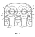
Now referring to FIGS. 4 and 5, in a second embodiment the first and second
angle gear arrangements 40,42 are configured for use with concentric tower shafts
36,38 and side-by- side lay shafts 44,46. In this embodiment, the first angle gear
arrangement 40 includes a ninth bevel gear 72 and a tenth bevel gear 74. The ninth
bevel gear 72 is attached to the first tower shaft 36. The ninth bevel gear 72 is
engaged with the tenth bevel gear 74, which is fixed to the first lay shaft 44. The
second gear arrangement 42 includes a first spur gear 76, a second spur gear 78, an
intermediate shaft 80, an eleventh bevel gear 82, and a twelfth bevel gear 84. The
first spur gear 76 is fixed (e.g., by one or more splines) to the second tower shaft 38.
The second spur gear 78 and the eleventh bevel gear 82 are attached to the
intermediate shaft 80. The second spur gear 78 is aligned and engaged with the first
spur gear 76. The eleventh bevel gear 82 is engaged with the twelfth bevel gear 84,
which is fixed to the second lay shaft 46.
In the second embodiment, the first and second lay shafts 44,46 are disposed
side-by-side, rotatable about lengthwise extending parallel axes 86,88. The first and
second lay shafts 44,46 are shown in phantom in FIG.4, extending out of the page.
The parallel axes 86,88 along which the side-by- side lay shafts 44,46 extend,
therefore also extend out of the page. The lay shafts 44,46 are shown extending
lengthwise within the page, in the sectional top view of FIG.5. The lay shafts 44,46
each include one or more bearing mounts 90 to positionally locate and to facilitate
rotation of the respective lay shaft 44,46. A coupling (not shown) is attached to, or
formed with, the other end of each lay shaft 44,46, for connecting the respective lay
shaft to the accessory gearbox 24.
Referring to FIG.2, in the operation of the engine 10 rotation of the low-pressure
drive shaft 14 rotationally drives the LPDS gear arrangement 32. The
LPDS gear arrangement 32, in turn, drives the second tower shaft 38 about its axis
56. Rotation of the high-pressure drive shaft 12 rotationally drives the HPDS gear
arrangement 34. The HPDS gear arrangement 34, in turn, drives the first tower shaft
36 about its axis 56.
Referring to FIG.3, in the first embodiment wherein the tower shafts 36,38 and
the lay shafts 44,46 are concentric, rotation of the first tower shaft 36 causes the first
angle gear arrangement 40 to rotate and drive the first lay shaft 44 (disposed radially
inside of the second lay shaft 46). Rotation of the second tower shaft 38 causes the
second angle gear arrangement 42 to rotate and drive the second lay shaft 46
(disposed radially outside of the first lay shaft 44). The concentric lay shafts 44,46,
in turn, drive the accessory gearbox 24.
Referring to FIGS. 4 and 5, in the second embodiment wherein the tower
shafts 36,38 are concentric and the lay shafts 44,46 side-by-side, rotation of the first
tower shaft 36 causes the first angle gear arrangement 40 to drive the first lay shaft
44. Rotation of the second tower shaft 38 causes the second gear arrangement 42
to drive the second lay shaft 46. The second gear arrangement 42 connects the
second lay shaft 46 (positioned side-by-side with, and therefor spaced apart from,
the first lay shaft 44) to the second tower shaft 38 via the intermediate shaft 80. The
side-by- side lay shafts 44,46, in turn, drive the accessory gearbox 24.
Although this invention has been shown and described with respect to the
detailed embodiments thereof, it will be understood by those skilled in the art that
various changes in form and detail thereof may be made without departing from the
scope of the invention. For example, the invention is described above using bevel
gears and spur gears in certain configurations. The concentric and side-by-side
configurations could also be accomplished using alternative gear arrangements.
Claims (9)
- A mechanical drive system for an accessory gearbox (24) of a gas turbine engine, which engine has a high-pressure drive shaft (12) and a low-pressure drive shaft (14), the drive system comprising:wherein the accessory gearbox (24) is driven by the first tower shaft (36) and the second tower shaft (38).a first tower shaft (36) connected by a first gear arrangement (34) to the high-pressure drive shaft (12); anda second tower shaft (38) connected by a second gear arrangement (32) to the low-pressure drive shaft (14);
- The mechanical drive system of claim 1, wherein the first tower shaft (36) is concentric with the second tower shaft (38).
- The mechanical drive system of claim 2, wherein the first gear arrangement (34) includes a first bevel gear (52) attached to the high-pressure drive shaft (12), and a second bevel gear (54) attached to the first tower shaft (36), wherein the first bevel gear (52) and the second bevel gear (54) are engaged with one another.
- The mechanical drive system of claim 2, wherein the second gear arrangement (32) includes a first spur gear (43), a second spur gear (45), an intermediate shaft (47), a first bevel gear (48), and a second bevel gear (50), wherein the first spur gear (43) is attached to the low-pressure drive shaft (14), and the second spur gear (45) and the first bevel gear (48) are attached to the intermediate shaft (47), and the second bevel gear (50) is attached to the second tower shaft (38);
wherein the first spur gear (43) and the second spur gear (45) are engaged with one another; and
wherein the first bevel gear (48) and the second bevel gear (50) are engaged with one another. - A mechanical drive system for an accessory gearbox (24) of a gas turbine engine, which engine has a high-pressure drive shaft (12) and a low-pressure drive shaft (14), the drive system comprising:wherein the accessory gearbox (24) is driven by the first tower shaft (36) and the second tower shaft (38).a first tower shaft (36) driven by the high-pressure drive shaft (12); anda second tower shaft (38) driven by the low-pressure drive shaft (14);
- The mechanical drive system of claim 5, wherein the first tower shaft (36) is concentric with the second tower shaft (38).
- The mechanical drive system of claim 6, wherein a first gear arrangement (34) connects the first tower shaft (36) to the high-pressure drive shaft (12), and the first gear arrangement includes a first bevel gear (52) attached to the high-pressure drive shaft (12), and a second bevel gear (54) attached to the first tower shaft (36), wherein the first bevel gear (52) and the second bevel gear (54) are engaged with one another.
- The mechanical drive system of claim 7, wherein a second gear arrangement (32) connects the low-pressure drive shaft (14) to the second tower shaft (38), and the second gear arrangement (32) includes a first spur gear (43), a second spur gear (45), an intermediate shaft (47), a first bevel gear (48), and a second bevel gear (50);
wherein the first spur gear (43) is attached to the low-pressure drive shaft (14), and the second spur gear (45) and the first bevel gear (48) are attached to the intermediate shaft (47), and the second bevel gear (50) is attached to the second tower shaft (38);
wherein the first spur gear (43) and the second spur gear (45) are engaged with one another; and
wherein the first bevel gear (48) and the second bevel gear (50) are engaged with one another. - A gas turbine engine, comprising:wherein the high-pressure drive shaft and the low-pressure drive shaft rotate about an axially extending engine centerline (28);a high-pressure drive shaft (12) connected to a high-pressure compressor 18 and a high-pressure turbine 20;a low-pressure drive shaft (14) connected to a low-pressure compressor (16) and a low-pressure turbine (22);
an accessory gear box (24); and
a mechanical drive system as claimed in any preceding claim.
Applications Claiming Priority (2)
| Application Number | Priority Date | Filing Date | Title |
|---|---|---|---|
| US784926 | 2004-02-25 | ||
| US10/784,926 US20050183540A1 (en) | 2004-02-25 | 2004-02-25 | Apparatus for driving an accessory gearbox in a gas turbine engine |
Publications (1)
| Publication Number | Publication Date |
|---|---|
| EP1574687A1 true EP1574687A1 (en) | 2005-09-14 |
Family
ID=34827562
Family Applications (1)
| Application Number | Title | Priority Date | Filing Date |
|---|---|---|---|
| EP05251095A Withdrawn EP1574687A1 (en) | 2004-02-25 | 2005-02-24 | Mechanical drive system for an accessory gearbox |
Country Status (3)
| Country | Link |
|---|---|
| US (1) | US20050183540A1 (en) |
| EP (1) | EP1574687A1 (en) |
| JP (1) | JP2005241006A (en) |
Cited By (5)
| Publication number | Priority date | Publication date | Assignee | Title |
|---|---|---|---|---|
| EP1911938A1 (en) * | 2006-10-13 | 2008-04-16 | Snecma | Turbofan |
| EP2028352A1 (en) * | 2007-08-23 | 2009-02-25 | Snecma | Gas turbine engine with means of driving the turbine accessory drive gearbox assembly and method of assembling said engine |
| RU2711895C2 (en) * | 2017-06-19 | 2020-01-23 | Публичное акционерное общество "ОДК-Уфимское моторостроительное производственное объединение" | Double-flow jet turbine engine |
| EP3628849A1 (en) * | 2018-09-25 | 2020-04-01 | United Technologies Corporation | Thrust balance control with differential power extraction |
| EP3696392A1 (en) * | 2019-02-13 | 2020-08-19 | United Technologies Corporation | Angle accessory gearbox for gas turbine engine |
Families Citing this family (20)
| Publication number | Priority date | Publication date | Assignee | Title |
|---|---|---|---|---|
| US7386983B2 (en) * | 2004-02-25 | 2008-06-17 | United Technologies Corporation | Apparatus for driving an accessory gearbox in a gas turbine engine |
| US7832193B2 (en) * | 2006-10-27 | 2010-11-16 | General Electric Company | Gas turbine engine assembly and methods of assembling same |
| WO2008082336A1 (en) * | 2006-12-29 | 2008-07-10 | Volvo Aero Corporation | A power transmission device for a gas turbine engine, an aeroplane and a method for operating a gas turbine engine |
| WO2008082335A1 (en) * | 2006-12-29 | 2008-07-10 | Volvo Aero Corporation | A power transmission device for a gas turbine engine |
| US9719428B2 (en) * | 2007-11-30 | 2017-08-01 | United Technologies Corporation | Gas turbine engine with pylon mounted accessory drive |
| US20090188334A1 (en) * | 2008-01-25 | 2009-07-30 | United Technologies Corp. | Accessory Gearboxes and Related Gas Turbine Engine Systems |
| US20090205341A1 (en) * | 2008-02-20 | 2009-08-20 | Muldoon Marc J | Gas turbine engine with twin towershaft accessory gearbox |
| US8172512B2 (en) * | 2008-04-23 | 2012-05-08 | Hamilton Sundstrand Corporation | Accessory gearbox system with compressor driven seal air supply |
| GB0903935D0 (en) * | 2009-03-09 | 2009-04-22 | Rolls Royce Plc | Gas turbine engine |
| US9816441B2 (en) * | 2009-03-30 | 2017-11-14 | United Technologies Corporation | Gas turbine engine with stacked accessory components |
| FR3007458B1 (en) * | 2013-06-21 | 2017-11-10 | Snecma | IMPROVED TURBOMACHINE INTERMEDIATE CASE AND ACCESSORY BOX DRIVE ASSEMBLY |
| FR3017658B1 (en) * | 2014-02-18 | 2019-04-12 | Safran Transmission Systems | EQUIPMENT DRIVE HOUSING FOR TURBOMACHINE |
| US11131208B2 (en) * | 2016-09-01 | 2021-09-28 | Rolls-Royce North American Technologies, Inc. | Embedded electric generator in turbine engine |
| US10995673B2 (en) * | 2017-01-19 | 2021-05-04 | Raytheon Technologies Corporation | Gas turbine engine with intercooled cooling air and dual towershaft accessory gearbox |
| US10634062B2 (en) | 2017-03-21 | 2020-04-28 | United Technologies Corporation | Two-shaft tower shaft support |
| US10358981B2 (en) * | 2017-04-11 | 2019-07-23 | United Technologies Corporation | High and low spool accessory gearbox drive |
| US11053858B2 (en) * | 2019-02-07 | 2021-07-06 | Raytheon Technologies Corporation | Low leakage seal for tower shaft |
| US11608784B2 (en) | 2019-02-13 | 2023-03-21 | Raytheon Technologies Corporation | Accessory gearbox for gas turbine engine with compressor drive |
| US11346427B2 (en) | 2019-02-13 | 2022-05-31 | Raytheon Technologies Corporation | Accessory gearbox for gas turbine engine with variable transmission |
| US20260092565A1 (en) * | 2024-09-30 | 2026-04-02 | Pratt & Whitney Canada Corp. | Gas Turbine Engine Tower Shaft Assembly |
Citations (5)
| Publication number | Priority date | Publication date | Assignee | Title |
|---|---|---|---|---|
| GB839961A (en) * | 1956-11-01 | 1960-06-29 | Bristol Siddeley Engines Ltd | Improvements in or relating to engine accessory mounting arrangements |
| GB973388A (en) * | 1963-05-24 | 1964-10-28 | George Garnham Turner | Accessory power drive mechanism for a gas turbine engine |
| US4776163A (en) * | 1986-07-01 | 1988-10-11 | Kloeckner-Humboldt-Deutz Ag | Gas turbine power unit |
| US5694765A (en) * | 1993-07-06 | 1997-12-09 | Rolls-Royce Plc | Shaft power transfer in gas turbine engines with machines operable as generators or motors |
| EP1479889A2 (en) * | 2003-05-21 | 2004-11-24 | ROLLS-ROYCE plc | Gas turbine engine and intake for a gas turbine engine with a device to prevent ice forming |
Family Cites Families (4)
| Publication number | Priority date | Publication date | Assignee | Title |
|---|---|---|---|---|
| US2952973A (en) * | 1958-06-02 | 1960-09-20 | Gen Motors Corp | Turbofan-ramjet engine |
| US3100378A (en) * | 1960-11-14 | 1963-08-13 | Avco Corp | Auxiliary power drive mechanism for a gas turbine engine |
| GB9606546D0 (en) * | 1996-03-28 | 1996-06-05 | Rolls Royce Plc | Gas turbine engine system |
| FR2826052B1 (en) * | 2001-06-19 | 2003-12-19 | Snecma Moteurs | RELIEF DEVICE FOR THE IGNITION OF A SELF-ROTATING TURBO-JET |
-
2004
- 2004-02-25 US US10/784,926 patent/US20050183540A1/en not_active Abandoned
-
2005
- 2005-02-01 JP JP2005024658A patent/JP2005241006A/en active Pending
- 2005-02-24 EP EP05251095A patent/EP1574687A1/en not_active Withdrawn
Patent Citations (5)
| Publication number | Priority date | Publication date | Assignee | Title |
|---|---|---|---|---|
| GB839961A (en) * | 1956-11-01 | 1960-06-29 | Bristol Siddeley Engines Ltd | Improvements in or relating to engine accessory mounting arrangements |
| GB973388A (en) * | 1963-05-24 | 1964-10-28 | George Garnham Turner | Accessory power drive mechanism for a gas turbine engine |
| US4776163A (en) * | 1986-07-01 | 1988-10-11 | Kloeckner-Humboldt-Deutz Ag | Gas turbine power unit |
| US5694765A (en) * | 1993-07-06 | 1997-12-09 | Rolls-Royce Plc | Shaft power transfer in gas turbine engines with machines operable as generators or motors |
| EP1479889A2 (en) * | 2003-05-21 | 2004-11-24 | ROLLS-ROYCE plc | Gas turbine engine and intake for a gas turbine engine with a device to prevent ice forming |
Cited By (12)
| Publication number | Priority date | Publication date | Assignee | Title |
|---|---|---|---|---|
| EP1911938A1 (en) * | 2006-10-13 | 2008-04-16 | Snecma | Turbofan |
| FR2907167A1 (en) * | 2006-10-13 | 2008-04-18 | Snecma Sa | GEARBOX DRIVE SHAFT OF AUXILIARY MACHINES OF A TURBOJET ENGINE; MODULAR SUPPLEMENTARY AUXILIARY MACHINE |
| US8042341B2 (en) | 2006-10-13 | 2011-10-25 | Snecma | Turbojet engine accessory gear box driveshaft; modular additional accessory |
| RU2442000C2 (en) * | 2006-10-13 | 2012-02-10 | Снекма | Double-flow turbojet engine with the intermediate jacket, with the drive shaft of transfer gearbox for turbojet engine accessory drive |
| EP2028352A1 (en) * | 2007-08-23 | 2009-02-25 | Snecma | Gas turbine engine with means of driving the turbine accessory drive gearbox assembly and method of assembling said engine |
| FR2920191A1 (en) * | 2007-08-23 | 2009-02-27 | Snecma Sa | GAS TURBINE ENGINE WITH DRIVING MEANS FOR THE ACCESSORIES HOUSING AND METHOD OF MOUNTING THE SAME |
| US8074455B2 (en) | 2007-08-23 | 2011-12-13 | Snecma | Gas turbine engine with a means of driving the accessory gear box, and method of fitting said engine |
| RU2476701C2 (en) * | 2007-08-23 | 2013-02-27 | Снекма | Gas turbine engine with auxiliary equipment unit gearing drive, and method of mounting said engine |
| RU2711895C2 (en) * | 2017-06-19 | 2020-01-23 | Публичное акционерное общество "ОДК-Уфимское моторостроительное производственное объединение" | Double-flow jet turbine engine |
| EP3628849A1 (en) * | 2018-09-25 | 2020-04-01 | United Technologies Corporation | Thrust balance control with differential power extraction |
| US10920671B2 (en) | 2018-09-25 | 2021-02-16 | Raytheon Technologies Corporation | Thrust balance control with differential power extraction |
| EP3696392A1 (en) * | 2019-02-13 | 2020-08-19 | United Technologies Corporation | Angle accessory gearbox for gas turbine engine |
Also Published As
| Publication number | Publication date |
|---|---|
| JP2005241006A (en) | 2005-09-08 |
| US20050183540A1 (en) | 2005-08-25 |
Similar Documents
| Publication | Publication Date | Title |
|---|---|---|
| US7386983B2 (en) | Apparatus for driving an accessory gearbox in a gas turbine engine | |
| US7055330B2 (en) | Apparatus for driving an accessory gearbox in a gas turbine engine | |
| EP1574687A1 (en) | Mechanical drive system for an accessory gearbox | |
| US11041443B2 (en) | Multi-spool gas turbine engine architecture | |
| US10458340B2 (en) | Turbine shaft power take-off | |
| EP3321488B1 (en) | Gas turbine engine accessories arrangement | |
| EP3273033B1 (en) | Turbine shaft power take-off | |
| CN103225548B (en) | For the bevel gear arrangements structure of axial Accessory Gear Box | |
| US20180073429A1 (en) | Reverse flow gas turbine engine with offset rgb | |
| US11326523B2 (en) | Gas turbine engine with accessory gearbox | |
| WO2014052269A1 (en) | Off-take power ratio | |
| CA2971053A1 (en) | Turbine shaft power take-off | |
| US20160333793A1 (en) | Accessory gearbox assembly for an aircraft turbine engine | |
| EP3561263B1 (en) | Gear assembly for coaxial shafts in gas turbine engine | |
| US9091214B2 (en) | Reduced gearbox size by separate electrically powered engine oil system |
Legal Events
| Date | Code | Title | Description |
|---|---|---|---|
| PUAI | Public reference made under article 153(3) epc to a published international application that has entered the european phase |
Free format text: ORIGINAL CODE: 0009012 |
|
| AK | Designated contracting states |
Kind code of ref document: A1 Designated state(s): AT BE BG CH CY CZ DE DK EE ES FI FR GB GR HU IE IS IT LI LT LU MC NL PL PT RO SE SI SK TR |
|
| AX | Request for extension of the european patent |
Extension state: AL BA HR LV MK YU |
|
| 17P | Request for examination filed |
Effective date: 20050816 |
|
| AKX | Designation fees paid |
Designated state(s): DE FR GB |
|
| STAA | Information on the status of an ep patent application or granted ep patent |
Free format text: STATUS: THE APPLICATION IS DEEMED TO BE WITHDRAWN |
|
| 18D | Application deemed to be withdrawn |
Effective date: 20060918 |