EP1574670A2 - A mounting arrangement for turbine blades - Google Patents
A mounting arrangement for turbine blades Download PDFInfo
- Publication number
- EP1574670A2 EP1574670A2 EP05251229A EP05251229A EP1574670A2 EP 1574670 A2 EP1574670 A2 EP 1574670A2 EP 05251229 A EP05251229 A EP 05251229A EP 05251229 A EP05251229 A EP 05251229A EP 1574670 A2 EP1574670 A2 EP 1574670A2
- Authority
- EP
- European Patent Office
- Prior art keywords
- arrangement
- cavity
- air
- entrainment
- open end
- Prior art date
- Legal status (The legal status is an assumption and is not a legal conclusion. Google has not performed a legal analysis and makes no representation as to the accuracy of the status listed.)
- Granted
Links
- 239000002826 coolant Substances 0.000 claims abstract description 44
- 238000001816 cooling Methods 0.000 claims abstract description 42
- 230000000694 effects Effects 0.000 claims description 10
- 238000009826 distribution Methods 0.000 description 4
- 230000003068 static effect Effects 0.000 description 4
- 238000007373 indentation Methods 0.000 description 3
- 230000001141 propulsive effect Effects 0.000 description 3
- 238000007493 shaping process Methods 0.000 description 3
- 230000001419 dependent effect Effects 0.000 description 2
- 230000014759 maintenance of location Effects 0.000 description 2
- 239000000463 material Substances 0.000 description 2
- 238000010926 purge Methods 0.000 description 2
- 230000001172 regenerating effect Effects 0.000 description 2
- 230000000717 retained effect Effects 0.000 description 2
- 238000002485 combustion reaction Methods 0.000 description 1
- 230000006835 compression Effects 0.000 description 1
- 238000007906 compression Methods 0.000 description 1
- 230000008878 coupling Effects 0.000 description 1
- 238000010168 coupling process Methods 0.000 description 1
- 238000005859 coupling reaction Methods 0.000 description 1
- 230000001627 detrimental effect Effects 0.000 description 1
- 238000010790 dilution Methods 0.000 description 1
- 239000012895 dilution Substances 0.000 description 1
- 239000000446 fuel Substances 0.000 description 1
- 238000010438 heat treatment Methods 0.000 description 1
- 238000012423 maintenance Methods 0.000 description 1
- 238000004519 manufacturing process Methods 0.000 description 1
- 238000000034 method Methods 0.000 description 1
- 239000000203 mixture Substances 0.000 description 1
- 238000010899 nucleation Methods 0.000 description 1
- 230000000149 penetrating effect Effects 0.000 description 1
- 239000000047 product Substances 0.000 description 1
- 230000001105 regulatory effect Effects 0.000 description 1
- 239000000243 solution Substances 0.000 description 1
- 125000006850 spacer group Chemical group 0.000 description 1
- 239000013589 supplement Substances 0.000 description 1
Images



Classifications
-
- F—MECHANICAL ENGINEERING; LIGHTING; HEATING; WEAPONS; BLASTING
- F01—MACHINES OR ENGINES IN GENERAL; ENGINE PLANTS IN GENERAL; STEAM ENGINES
- F01D—NON-POSITIVE DISPLACEMENT MACHINES OR ENGINES, e.g. STEAM TURBINES
- F01D5/00—Blades; Blade-carrying members; Heating, heat-insulating, cooling or antivibration means on the blades or the members
- F01D5/02—Blade-carrying members, e.g. rotors
- F01D5/08—Heating, heat-insulating or cooling means
- F01D5/081—Cooling fluid being directed on the side of the rotor disc or at the roots of the blades
- F01D5/082—Cooling fluid being directed on the side of the rotor disc or at the roots of the blades on the side of the rotor disc
-
- F—MECHANICAL ENGINEERING; LIGHTING; HEATING; WEAPONS; BLASTING
- F05—INDEXING SCHEMES RELATING TO ENGINES OR PUMPS IN VARIOUS SUBCLASSES OF CLASSES F01-F04
- F05D—INDEXING SCHEME FOR ASPECTS RELATING TO NON-POSITIVE-DISPLACEMENT MACHINES OR ENGINES, GAS-TURBINES OR JET-PROPULSION PLANTS
- F05D2240/00—Components
- F05D2240/80—Platforms for stationary or moving blades
- F05D2240/81—Cooled platforms
-
- Y—GENERAL TAGGING OF NEW TECHNOLOGICAL DEVELOPMENTS; GENERAL TAGGING OF CROSS-SECTIONAL TECHNOLOGIES SPANNING OVER SEVERAL SECTIONS OF THE IPC; TECHNICAL SUBJECTS COVERED BY FORMER USPC CROSS-REFERENCE ART COLLECTIONS [XRACs] AND DIGESTS
- Y02—TECHNOLOGIES OR APPLICATIONS FOR MITIGATION OR ADAPTATION AGAINST CLIMATE CHANGE
- Y02T—CLIMATE CHANGE MITIGATION TECHNOLOGIES RELATED TO TRANSPORTATION
- Y02T50/00—Aeronautics or air transport
- Y02T50/60—Efficient propulsion technologies, e.g. for aircraft
Definitions
- the present invention relates to mounting arrangements for turbine blades in an engine and more particularly to providing an arrangement for more effective cooling of blade platform portions.
- a gas turbine engine is generally indicated at 10 and comprises, in axial flow series, an air intake 11, a propulsive fan 12, an intermediate pressure compressor 13, a high pressure compressor 14, a combustor 15, a turbine arrangement comprising a high pressure turbine 16, an intermediate pressure turbine 17 and a low pressure turbine 18, and an exhaust nozzle 19.
- the gas turbine engine 10 operates in a conventional manner so that air entering the intake 11 is accelerated by the fan 12 which produce two air flows: a first air flow into the intermediate pressure compressor 13 and a second air flow which provides propulsive thrust.
- the intermediate pressure compressor compresses the air flow directed into it before delivering that air to the high pressure compressor 14 where further compression takes place.
- the compressed air exhausted from the high pressure compressor 14 is directed into the combustor 15 where it is mixed with fuel and the mixture combusted.
- the resultant hot combustion products then expand through, and thereby drive, the high, intermediate and low pressure turbines 16, 17 and 18 before being exhausted through the nozzle 19 to provide additional propulsive thrust.
- the high, intermediate and low pressure turbines 16, 17 and 18 respectively drive the high and intermediate pressure compressors 14 and 13 and the fan 12 by suitable interconnecting shafts.
- the present invention in particular relates to mounting arrangements for turbine blades in order to provide more efficient cooling for blade platforms.
- Fig. 2 is a schematic perspective view of a prior nozzle guide vane and turbine blade cooling arrangement.
- the present invention particularly relates to mounting arrangements for turbine blades 118.
- high pressure coolant air 100 passes through apertures 101 and pre-swirler nozzles 102 into a plenum chamber 103 where it is distributed to root galleries 104 at the base of each blade 118.
- This coolant air also circulates into blade pockets 105 formed between adjacent blades 118 in order to provide some additional cooling of blades via cooling passage 120 below the blade platform 106.
- coolant air 107, 108, 109 is presented through apertures in guide nozzles 110 and the blades 118 in order to provide surface cooling for these components.
- Coolant air flows are controlled and regulated through passageways, apertures and nozzles in order to maximise the cooling effect.
- the pre swirler nozzles 102 act to reduce temperature and pressure of the cooling air flow 100 as it is presented to the rotor disc assembly for cooling purposes.
- a particular problem relates to the space, commonly referred to as the wheel space, in front of each rotor disc assembly upon which turbine blades are secured.
- the air within these spaces has tended to be warmed and is of lower cooling quality due to passing through a rotor stator cavity where it has been exposed to windage and drag from the static components adjacent to the rotor disc. It will be understood for cooling efficiency, it is desirable for there to be a positive flow of relatively cool air.
- air has been taken from these fore and aft wheel spaces with the result that inefficient cooling has occurred.
- a mounting arrangement for a turbine engine blade in an engine comprising a blade associated with a rotor disc assembly with a cavity between them, the cavity having an open end, the arrangement characterised in that a surface of the rotor disc assembly which extends from the open end includes entrainment features to direct a curtain airflow across the open end to create in use effective coolant air containment within the cavity.
- the entrainment features comprise striations or slots or grooves formed in the surface.
- the entrainment features are integral with the surface.
- the entrainment features extend from a coolant plenum chamber within the rotor disc assembly to the open end of the cavity. Possibly, the entrainment features are angled to utilise rotary effects present in operation.
- the surface is part of a wheel space to one side of the rotor disc assembly.
- a primary coolant airflow passes through a root gallery into the cavity.
- the cavity includes bleed apertures 50 to facilitate throughput of coolant air flows within the cavity.
- the bleed apertures are at an opposite end of the cavity to the open end in order to draw the curtain flow as a coolant air flow across a cavity surface therebetween.
- the bleed apertures are configured and/or positioned in order to optimise the throughput of air flows through the cavity for cooling effect.
- the cooling of the blade platform and throughput of air maintains acceptable blade platform and disc temperatures.
- the entrainment features are tapered in a radially outward direction and they are part circular in cross-section.
- the entrainment features are defined by at least two substantially flat surfaces.
- the entrainment features do not break out of the radially outer edge of their defining surface.
- the entrainment features break out of the radially outer edge of their defining surface.
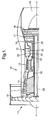
- FIG. 3 illustrating a cross-section of a mounting arrangement 31 in accordance with the present invention.
- the arrangement 31 comprises a turbine blade 32 associated with a rotor disc 33 with appropriate seals and couplings to ensure location.
- the turbine blade 32 is secured through a fir tree or other connection to ensure retention upon the disc 33 when rotated.
- the present invention in particular relates to providing cooling to a blade platform section 34 through a blade pocket cavity 35.
- wheel spaces 36, 37 which as indicated previously generally are filled with air less acceptable for cooling purposes due to lower rotational velocity relative to the disc assembly and which is subjected to significant heating by the associated static components and surfaces about these wheel spaces 36, 37.
- this volume of relatively stagnant but hot air in the wheel spaces 36, 37 is prevented from entering the blade cavity.
- coolant air passes through a pre swirler nozzle (not shown) in the direction of arrowhead 38 through an aperture 39 into a plenum chamber 40.
- This plenum chamber 40 generally is formed as a distribution reservoir about the whole rotor disc 33/blade 32 assembly, which it will be appreciated in practice will comprise a large number of blades 32 secured to the rotor disc 33.
- a labyrinth seal 41 is provided between the rotating disc 33 with blades 32 and the static engine structures 42 such that the coolant air flow 38 does not leak into the wheel space 36 directly.
- this coolant airflow 38 It is more effective utilisation of this coolant airflow 38 which achieves the higher cooling efficiency of the present arrangement 31. It will be understood previously this coolant airflow has been less efficient hotter air from the wheel spaces 36, 37 through an open end 45 of the blade pocket cavity 35. Entry or purging of such hotter wheel space 36, 37 air into the blade cavity is at least inhibited by the created air curtain across the opening.
- a surface 46 extends from the open end 45 to the plenum chamber 40.
- This surface 46 includes entrainment features such as striations or slots or grooves whereby a proportion of the coolant air flow 38 entering the plenum chamber 40 is entrained by these features. In such circumstances, this proportion of the coolant air flow 38 is presented across the open end 45 in order to create an air curtain essentially isolating and separating the cavity 35 whereby there is limited if any dilution of the coolant air within the cavity 35 presented from the wheel space 36.
- an edge 56 of the open end 45 is configured in order to provide a desired launch orientation for the air curtain created across the open end 45.
- a receiving edge 47 of the open end 45 may be shaped in order to receive or scoop the air curtain and direct at least a portion of it along a cavity surface 48 for cooling of that surface 48 and therefore the platform 34.
- bleed apertures in the form of micro-apertures 49 in the platform 34 and/or a sink aperture 50 are provided.
- the micro apertures 49 essentially draw coolant air flow 51 taken from the air curtain flow presented across the open end 45.
- the sink aperture 50 draws that air flow 51 for cooling effect maintenance through bleed and replenishment with further coolant air from the plenum 40.
- the relative sizes of the micro apertures 49 and sink aperture 50 will be determined by particular mounting arrangement requirements relative to coolant air flow rates and desired operating temperatures and efficiencies.
- the entrainment features in the form of slots or grooves in the surface 46 traverse a portion of a retainer cover plate 52, so there is a degree of jetting of the air flow through the entrainment grooves or slots.
- This initial jet entrainment may be further enhanced by shaping of the entrainment grooves or slots to utilise centrifugal or other rotational force as well as through structural shaping of the grooves or slots to ensure an adequate air curtain is presented across the open end 45 of the cavity 35.
- Such structural shaping may include angular orientation of the grooves or slots and varying cross-sectional geometry along their length.
- the entrainment features in the form of grooves or slots may again be shaped and angled to facilitate more forceful jetting across the open end 45 for a greater efficiency with respect to forming a containment air curtain for the cavity 35.
- the receiving edge 47 will be shaped and angled to act as a guide scoop for the air curtain projected across the open end 45 to facilitate air flow along the cavity surface 48. This air flow is further stimulated by bleed drawing through the micro apertures 49 and the sink aperture 50.
- the specific sizes, shapes and distribution of the entrainment feature as slots or grooves, edges 45, 47 and apertures 49, 50 will be chosen dependent upon operational mounting arrangement configurations and desired performance.
- this space 36 is relatively stagnant due to the drag imposed on the air by the static components 42 and the labyrinth seal 41 and so will generally not present too great a penetrative pressure to force entry across the air curtain created by the coolant air flow through the entrainment grooves or slots in the surface 46.
- the apertures 49, 50 may be angled against the direction of rotation for the disc 33 in order to recover useful energy from the coolant air as it expands into the general turbine gas path of an engine. Such configuration of the apertures 49, 50 will reduce the detrimental performance impacts associated with using cooling air at these locations.
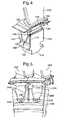
- Fig. 4 is a front perspective view of a mounting arrangement in accordance with the present invention with the retainer cover plate removed, similar reference numerals have been used for consistency of description but incremented by 100 from Fig. 3.
- a rotor disc 133 includes an indented plenum chamber portion 140 which will form part of the plenum chamber in association with a retainer cover plate (not shown).
- the coolant air flow 138 will pass into the thus formed plenum chamber such that a proportion enters the root gallery 143 for movement through passageways (not shown) into the blade.
- entrainment slots 146 are provided which extend directly upwards to an open end 145 of a cavity 135.
- the proportion of the air flow 138 which passes through the grooves 146 creates an air curtain at the open end 145 essentially containing coolant air within the cavity 135 for cooling efficiency with respect to a blade platform 134 as well as the disc 153 outer edge.
- An edge 147 is configured to receive the proportion of air flow 138 through the grooves 146 in order that this flow is drawn along a cavity surface 148 of the platform 134 for greater cooling efficiency.
- Fig. 5 provides a front view illustrating two mounting arrangements in accordance with the present invention side by side. Similar reference numerals have been used for description consistency but incremented by 200 from Fig. 3.
- a plenum chamber is formed between plenum indentation 240 and a retainer cover plate (not shown). This plenum chamber extends into root galleries 243 which extend below blades 232 such that coolant air flow passes through passages 244 in order to provide coolant air for blade cooling.
- entrainment slots or grooves 246 extend from the plenum indentation 240 upwards to the cavity 235 in order to create an air curtain which encapsulates and contains the coolant air within the cavity 235.
- this air curtain passes along an interior surface of the cavity 235 for greater cooling effect.
- the distribution, size and cross-sectional dimensions of the entrainment slots or grooves will be chosen in order to achieve the greatest efficiency in forming an appropriate air curtain for containment of the cavity 235 as well as the cooling effect within the cavity 235.
- the air flow through the entrainment slots or grooves principally prevents ingress of hotter air in a wheel space in front of the open end of the cavity 235 and provides cooling air to the cavity.
- This cooling air may supplement cooling air presented by other means from the root gallery 243 to the cavity 235.
- apertures were normally provided within the cavity 235 to bleed or draw coolant air for cavity cooling air regenerative purposes to improve cooling efficiency within the cavity 235.
- Fig. 6 is a front perspective view of a mounting arrangement in accordance with the present invention with the retainer cover plate removed, similar reference numerals have been used for consistency of description with respect to Figs. 4 and 5.
- entrainment slots or grooves 246 extend between the plenum indentation 240 (Fig. 5) upwards to the cavity 235 in order to create an air curtain which encapsulates and contains the coolant air within the cavity 235.
- the grooves 246 are tapering, in depth and width, in the radially outward direction.
- Fig. 6 shows the grooves 246 terminating before breaking out of a radially outward edge 250 of the disc (post) 133, however, they may also break out of the radially outward edge 250.
- the tapering grooves 246 are arranged such that they provide a wider distribution of cool air over the opening at the front of the blade shank cavity, so preventing the ingress of hotter lower quality air from the wheel space.
- This embodiment has the additional benefit of seeding the air adjacent to the disc/blade front surface (or open end 145) with cooler air from the groove 246.
- arrow 252 shows the general direction of air flow being directed across the opening of the blade shank cavity 235 and arrows 254 show the general direction air flow spilling out of the groove 246 over the disc/blade front face or open end 145.
- the groove 246 is configured to taper in cross-sectional area.
- either the depth or the width of the groove 246 may be varied.
- the groove 246 is defined by a part circular surface of constant radius, thus the groove 246 tapers both in depth and width.
- the groove may also be defined by two or more flat surfaces.
- the entrainment features provided in order to create the air curtain may take the form of pipes or conduits drilled beneath the surface of the rotor disc post, but clearly this would require a more complex fabrication process.
- the entrainment grooves or slots will be integral with the rotor disc post but may be formed by attached spacer strips or ribs secured or located relative to the surface as required for spacing from the retainer cover plate, but also to enable entrainment of the air flow in order to create the desired air curtain across the open end of the cavity.
Landscapes
- Engineering & Computer Science (AREA)
- Mechanical Engineering (AREA)
- General Engineering & Computer Science (AREA)
- Turbine Rotor Nozzle Sealing (AREA)
Abstract
Description
Claims (15)
- A mounting arrangement (31) for a turbine engine blade (32, 132, 232) in an engine, the arrangement comprising a blade (32, 132, 232) associated with a rotor disc (33, 133) assembly with a cavity (35, 135, 235) between them, the cavity (35, 135, 235) having an open end (45, 145), the arrangement characterised in that a surface (46) of the rotor disc assembly which extends from the open end (45, 145) includes entrainment features (146, 246) to direct a curtain airflow across the open end (45, 145) for coolant air containment within the cavity (35, 135, 235).
- An arrangement as claimed in claim 1 wherein the entrainment features comprise striations or slots or grooves (146, 246) formed in the surface.
- An arrangement as claimed in claim 1 or claim 2 wherein the entrainment features are integral with the surface.
- An arrangement as claimed in claim 1, 2 or 3 wherein the entrainment features extend from a coolant plenum chamber (40, 140, 240) within the rotor disc assembly to the open end (45, 145) of the cavity (35, 135, 235).
- An arrangement as claimed in any preceding claim wherein the entrainment features are angled to utilize rotary effects present in operation.
- An arrangement as claimed in any preceding claim wherein the surface (46) is part of a wheel space (36) to one side of the rotor disc assembly.
- An arrangement as claimed in any preceding claim wherein the cavity includes bleed apertures (49, 50) to facilitate throughput of coolant air flows (51) within the cavity (35, 135, 235).
- An arrangement as claimed in claim 7 wherein the bleed apertures (49, 50) are at an opposite end of the cavity (35, 135, 235) to the open end (45, 145) in order to draw the air curtain flow as a coolant air flow (51) across a cavity surface (48, 148) therebetween.
- An arrangement as claimed in claim 7 or claim 8 wherein the bleed apertures (49, 50) are configured and/or positioned in order to utilise through rotational force evacuation throughput of air flows through the cavity (35, 135, 235) for cooling effect.
- An arrangement as claimed in any one of claims 1 to 9 wherein the entrainment features (146, 246) are tapered in a radially outward direction.
- An arrangement as claimed in any one of claims 1 to 10 wherein the entrainment features (146, 246) are part circular in cross-section.
- An arrangement as claimed in any one of claims 1 to 10 wherein the entrainment features (146, 246) are defined by at least two substantially flat surfaces.
- An arrangement as claimed in any one of claims 1 to 12 wherein the entrainment features (146, 246) do not break out of the radially outer edge (250) of their defining surface (46).
- An arrangement as claimed in any one of claims 1 to 12 wherein the entrainment features (146, 246) break out of the radially outer edge (250) of their defining surface (46).
- A turbine engine incorporating a mounting arrangement (31) as claimed in any preceding claim.
Applications Claiming Priority (2)
| Application Number | Priority Date | Filing Date | Title |
|---|---|---|---|
| GB0405679 | 2004-03-13 | ||
| GBGB0405679.2A GB0405679D0 (en) | 2004-03-13 | 2004-03-13 | A mounting arrangement for turbine blades |
Publications (3)
| Publication Number | Publication Date |
|---|---|
| EP1574670A2 true EP1574670A2 (en) | 2005-09-14 |
| EP1574670A3 EP1574670A3 (en) | 2009-02-25 |
| EP1574670B1 EP1574670B1 (en) | 2017-09-13 |
Family
ID=32117617
Family Applications (1)
| Application Number | Title | Priority Date | Filing Date |
|---|---|---|---|
| EP05251229.0A Ceased EP1574670B1 (en) | 2004-03-13 | 2005-03-01 | A mounting arrangement for turbine blades |
Country Status (3)
| Country | Link |
|---|---|
| US (1) | US7503748B2 (en) |
| EP (1) | EP1574670B1 (en) |
| GB (1) | GB0405679D0 (en) |
Cited By (8)
| Publication number | Priority date | Publication date | Assignee | Title |
|---|---|---|---|---|
| WO2009106045A1 (en) * | 2008-02-28 | 2009-09-03 | Mtu Aero Engines Gmbh | Device and method for redirecting a leakage current |
| EP1772592A3 (en) * | 2005-10-04 | 2010-12-08 | General Electric Company | Dust resistant platform blade |
| EP1653047A3 (en) * | 2004-10-27 | 2011-09-07 | Snecma | Gas turbine rotor blade |
| CN102705254A (en) * | 2010-11-05 | 2012-10-03 | 通用电气公司 | Shroud leakage cover |
| EP2246526A4 (en) * | 2008-02-27 | 2014-03-05 | Mitsubishi Heavy Ind Ltd | TURBINE DISC AND GAS TURBINE |
| EP3043024A1 (en) * | 2015-01-09 | 2016-07-13 | Siemens Aktiengesellschaft | Blade platform cooling and corresponding gas turbine |
| EP3101232A1 (en) * | 2015-06-01 | 2016-12-07 | United Technologies Corporation | Rotor disk, corresponding assembly and gas turbine engine |
| CN113339076A (en) * | 2020-03-03 | 2021-09-03 | 艾特帕新世代涡轮机有限责任公司 | Vane assembly for a gas turbine engine |
Families Citing this family (23)
| Publication number | Priority date | Publication date | Assignee | Title |
|---|---|---|---|---|
| US7534085B2 (en) * | 2006-06-21 | 2009-05-19 | United Technologies Corporation | Gas turbine engine with contoured air supply slot in turbine rotor |
| US8668437B1 (en) * | 2006-09-22 | 2014-03-11 | Siemens Energy, Inc. | Turbine engine cooling fluid feed system |
| US7870742B2 (en) * | 2006-11-10 | 2011-01-18 | General Electric Company | Interstage cooled turbine engine |
| WO2009019126A1 (en) * | 2007-08-08 | 2009-02-12 | Alstom Technology Ltd | Rotor arrangement of a turbine |
| US20090110561A1 (en) * | 2007-10-29 | 2009-04-30 | Honeywell International, Inc. | Turbine engine components, turbine engine assemblies, and methods of manufacturing turbine engine components |
| US8152436B2 (en) * | 2008-01-08 | 2012-04-10 | Pratt & Whitney Canada Corp. | Blade under platform pocket cooling |
| US8226365B2 (en) * | 2009-04-22 | 2012-07-24 | General Electric Company | Systems, methods, and apparatus for thermally isolating a turbine rotor wheel |
| US8444387B2 (en) * | 2009-11-20 | 2013-05-21 | Honeywell International Inc. | Seal plates for directing airflow through a turbine section of an engine and turbine sections |
| EP2423435A1 (en) * | 2010-08-30 | 2012-02-29 | Siemens Aktiengesellschaft | Blade for a turbo machine |
| GB201016597D0 (en) * | 2010-10-04 | 2010-11-17 | Rolls Royce Plc | Turbine disc cooling arrangement |
| US8926267B2 (en) | 2011-04-12 | 2015-01-06 | Siemens Energy, Inc. | Ambient air cooling arrangement having a pre-swirler for gas turbine engine blade cooling |
| EP2520764A1 (en) * | 2011-05-02 | 2012-11-07 | MTU Aero Engines GmbH | Blade with cooled root |
| GB201113893D0 (en) * | 2011-08-12 | 2011-09-28 | Rolls Royce Plc | Oil mist separation in gas turbine engines |
| US20130170966A1 (en) * | 2012-01-04 | 2013-07-04 | General Electric Company | Turbine cooling system |
| US10113434B2 (en) | 2012-01-31 | 2018-10-30 | United Technologies Corporation | Turbine blade damper seal |
| RU2493371C1 (en) * | 2012-05-11 | 2013-09-20 | Открытое акционерное общество "Авиадвигатель" | Turbojet turbine rotor |
| US9243500B2 (en) * | 2012-06-29 | 2016-01-26 | United Technologies Corporation | Turbine blade platform with U-channel cooling holes |
| WO2015112226A2 (en) * | 2013-12-19 | 2015-07-30 | United Technologies Corporation | Blade feature to support segmented coverplate |
| EP3109402A1 (en) | 2015-06-26 | 2016-12-28 | Alstom Technology Ltd | Method for cooling a turboengine rotor, and turboengine rotor |
| DE102016124806A1 (en) * | 2016-12-19 | 2018-06-21 | Rolls-Royce Deutschland Ltd & Co Kg | A turbine blade assembly for a gas turbine and method of providing sealing air in a turbine blade assembly |
| EP3342979B1 (en) * | 2016-12-30 | 2020-06-17 | Ansaldo Energia Switzerland AG | Gas turbine comprising cooled rotor disks |
| FR3085420B1 (en) * | 2018-09-04 | 2020-11-13 | Safran Aircraft Engines | ROTOR DISC WITH BLADE AXIAL STOP, SET OF DISC AND RING AND TURBOMACHINE |
| US11255267B2 (en) * | 2018-10-31 | 2022-02-22 | Raytheon Technologies Corporation | Method of cooling a gas turbine and apparatus |
Citations (1)
| Publication number | Priority date | Publication date | Assignee | Title |
|---|---|---|---|---|
| EP1088963A2 (en) | 1999-09-30 | 2001-04-04 | General Electric Company | Method and apparatus for purging turbine wheel cavities |
Family Cites Families (16)
| Publication number | Priority date | Publication date | Assignee | Title |
|---|---|---|---|---|
| GB701263A (en) | 1950-08-03 | 1953-12-23 | Rolls Royce | Improvements in or relating to turbo-machines |
| US3356339A (en) * | 1966-12-12 | 1967-12-05 | Gen Motors Corp | Turbine rotor |
| US3663118A (en) * | 1970-06-01 | 1972-05-16 | Gen Motors Corp | Turbine cooling control |
| BE792286A (en) * | 1971-12-06 | 1973-03-30 | Gen Electric | BOLTLESS AUBA RETAINER FOR TURBOMACHIN ROTOR |
| FR2503247B1 (en) * | 1981-04-07 | 1985-06-14 | Snecma | IMPROVEMENTS ON THE FLOORS OF A GAS TURBINE OF TURBOREACTORS PROVIDED WITH AIR COOLING MEANS OF THE TURBINE WHEEL DISC |
| US5281097A (en) * | 1992-11-20 | 1994-01-25 | General Electric Company | Thermal control damper for turbine rotors |
| US5388962A (en) * | 1993-10-15 | 1995-02-14 | General Electric Company | Turbine rotor disk post cooling system |
| JP3652780B2 (en) * | 1996-04-08 | 2005-05-25 | 三菱重工業株式会社 | Turbine cooling system |
| US5800124A (en) * | 1996-04-12 | 1998-09-01 | United Technologies Corporation | Cooled rotor assembly for a turbine engine |
| EP0890781B1 (en) * | 1997-07-11 | 2005-05-04 | ROLLS-ROYCE plc | Gas turbine lubrication during starting |
| US5984636A (en) * | 1997-12-17 | 1999-11-16 | Pratt & Whitney Canada Inc. | Cooling arrangement for turbine rotor |
| US6059529A (en) * | 1998-03-16 | 2000-05-09 | Siemens Westinghouse Power Corporation | Turbine blade assembly with cooling air handling device |
| DE10043906A1 (en) * | 2000-09-06 | 2002-03-14 | Rolls Royce Deutschland | Vordralldüsenträger |
| FR2823794B1 (en) * | 2001-04-19 | 2003-07-11 | Snecma Moteurs | REPORTED AND COOLED DAWN FOR TURBINE |
| US6481959B1 (en) * | 2001-04-26 | 2002-11-19 | Honeywell International, Inc. | Gas turbine disk cavity ingestion inhibitor |
| US7192245B2 (en) * | 2004-12-03 | 2007-03-20 | Pratt & Whitney Canada Corp. | Rotor assembly with cooling air deflectors and method |
-
2004
- 2004-03-13 GB GBGB0405679.2A patent/GB0405679D0/en not_active Ceased
-
2005
- 2005-03-01 EP EP05251229.0A patent/EP1574670B1/en not_active Ceased
- 2005-03-02 US US11/068,912 patent/US7503748B2/en active Active
Patent Citations (1)
| Publication number | Priority date | Publication date | Assignee | Title |
|---|---|---|---|---|
| EP1088963A2 (en) | 1999-09-30 | 2001-04-04 | General Electric Company | Method and apparatus for purging turbine wheel cavities |
Cited By (14)
| Publication number | Priority date | Publication date | Assignee | Title |
|---|---|---|---|---|
| EP1653047A3 (en) * | 2004-10-27 | 2011-09-07 | Snecma | Gas turbine rotor blade |
| EP1772592A3 (en) * | 2005-10-04 | 2010-12-08 | General Electric Company | Dust resistant platform blade |
| US8770919B2 (en) | 2008-02-27 | 2014-07-08 | Mitsubishi Heavy Industries, Ltd. | Turbine disk and gas turbine |
| EP2246526A4 (en) * | 2008-02-27 | 2014-03-05 | Mitsubishi Heavy Ind Ltd | TURBINE DISC AND GAS TURBINE |
| WO2009106045A1 (en) * | 2008-02-28 | 2009-09-03 | Mtu Aero Engines Gmbh | Device and method for redirecting a leakage current |
| US8753070B2 (en) | 2008-02-28 | 2014-06-17 | Mtu Aero Engines Gmbh | Device and method for redirecting a leakage current |
| CN102705254A (en) * | 2010-11-05 | 2012-10-03 | 通用电气公司 | Shroud leakage cover |
| CN102705254B (en) * | 2010-11-05 | 2016-08-31 | 通用电气公司 | For guiding the system and method for leadage air |
| EP3043024A1 (en) * | 2015-01-09 | 2016-07-13 | Siemens Aktiengesellschaft | Blade platform cooling and corresponding gas turbine |
| WO2016110342A1 (en) * | 2015-01-09 | 2016-07-14 | Siemens Aktiengesellschaft | Blade platform cooling in a gas turbine |
| US10323523B2 (en) | 2015-01-09 | 2019-06-18 | Siemens Aktiengesellschaft | Blade platform cooling in a gas turbine |
| EP3101232A1 (en) * | 2015-06-01 | 2016-12-07 | United Technologies Corporation | Rotor disk, corresponding assembly and gas turbine engine |
| US9835032B2 (en) | 2015-06-01 | 2017-12-05 | United Technologies Corporation | Disk lug cooling flow trenches |
| CN113339076A (en) * | 2020-03-03 | 2021-09-03 | 艾特帕新世代涡轮机有限责任公司 | Vane assembly for a gas turbine engine |
Also Published As
| Publication number | Publication date |
|---|---|
| US20050201857A1 (en) | 2005-09-15 |
| EP1574670B1 (en) | 2017-09-13 |
| US7503748B2 (en) | 2009-03-17 |
| EP1574670A3 (en) | 2009-02-25 |
| GB0405679D0 (en) | 2004-04-21 |
Similar Documents
| Publication | Publication Date | Title |
|---|---|---|
| US7503748B2 (en) | Mounting arrangement for turbine blades | |
| US7632062B2 (en) | Turbine rotor blades | |
| US6609884B2 (en) | Cooling of gas turbine engine aerofoils | |
| EP3640432B1 (en) | Turbine shroud assemblies for gas turbine engines | |
| EP2436879B1 (en) | Turbine disc cooling arrangement | |
| CN108138654B (en) | Turboprop engine assembly with combined engine and cooled exhaust | |
| US7670103B2 (en) | Mounting arrangement for turbine blades | |
| EP3150803B1 (en) | Airfoil and method of cooling | |
| EP1001136B1 (en) | Airfoil with isolated leading edge cooling | |
| GB2270125A (en) | Tip cooled turbine blade. | |
| KR20080057183A (en) | Fire-nose sealed turbine stage | |
| US20070041835A1 (en) | Turbine blade including revised trailing edge cooling | |
| EP3168420A1 (en) | Shrouded turbine blade | |
| US20150300254A1 (en) | Propulsion engine | |
| EP2551458A2 (en) | Blade Cooling and Sealing System | |
| CN114508426B (en) | Thermal management system for a gas turbine engine | |
| EP3043024A1 (en) | Blade platform cooling and corresponding gas turbine | |
| US6506020B2 (en) | Blade platform cooling | |
| US7465149B2 (en) | Turbine engine cooling | |
| EP3693541B1 (en) | Gas turbine rotor disk having scallop shield feature | |
| EP2821622B1 (en) | Gas turbine engine | |
| US8419366B2 (en) | Blade | |
| JP2000008804A (en) | Gas turbine turbine blade vibration isolator | |
| GB2434842A (en) | Cooling arrangement for a turbine blade shroud | |
| EP1703081A1 (en) | Side plate |
Legal Events
| Date | Code | Title | Description |
|---|---|---|---|
| PUAI | Public reference made under article 153(3) epc to a published international application that has entered the european phase |
Free format text: ORIGINAL CODE: 0009012 |
|
| AK | Designated contracting states |
Kind code of ref document: A2 Designated state(s): AT BE BG CH CY CZ DE DK EE ES FI FR GB GR HU IE IS IT LI LT LU MC NL PL PT RO SE SI SK TR |
|
| AX | Request for extension of the european patent |
Extension state: AL BA HR LV MK YU |
|
| PUAL | Search report despatched |
Free format text: ORIGINAL CODE: 0009013 |
|
| AK | Designated contracting states |
Kind code of ref document: A3 Designated state(s): AT BE BG CH CY CZ DE DK EE ES FI FR GB GR HU IE IS IT LI LT LU MC NL PL PT RO SE SI SK TR |
|
| AX | Request for extension of the european patent |
Extension state: AL BA HR LV MK YU |
|
| 17P | Request for examination filed |
Effective date: 20090202 |
|
| 17Q | First examination report despatched |
Effective date: 20090908 |
|
| AKX | Designation fees paid |
Designated state(s): DE FR GB |
|
| RAP1 | Party data changed (applicant data changed or rights of an application transferred) |
Owner name: ROLLS-ROYCE PLC |
|
| STAA | Information on the status of an ep patent application or granted ep patent |
Free format text: STATUS: EXAMINATION IS IN PROGRESS |
|
| GRAP | Despatch of communication of intention to grant a patent |
Free format text: ORIGINAL CODE: EPIDOSNIGR1 |
|
| STAA | Information on the status of an ep patent application or granted ep patent |
Free format text: STATUS: GRANT OF PATENT IS INTENDED |
|
| GRAS | Grant fee paid |
Free format text: ORIGINAL CODE: EPIDOSNIGR3 |
|
| INTG | Intention to grant announced |
Effective date: 20170714 |
|
| GRAA | (expected) grant |
Free format text: ORIGINAL CODE: 0009210 |
|
| STAA | Information on the status of an ep patent application or granted ep patent |
Free format text: STATUS: THE PATENT HAS BEEN GRANTED |
|
| AK | Designated contracting states |
Kind code of ref document: B1 Designated state(s): DE FR GB |
|
| REG | Reference to a national code |
Ref country code: GB Ref legal event code: FG4D |
|
| REG | Reference to a national code |
Ref country code: DE Ref legal event code: R096 Ref document number: 602005052709 Country of ref document: DE |
|
| REG | Reference to a national code |
Ref country code: FR Ref legal event code: PLFP Year of fee payment: 14 |
|
| REG | Reference to a national code |
Ref country code: DE Ref legal event code: R097 Ref document number: 602005052709 Country of ref document: DE |
|
| PLBE | No opposition filed within time limit |
Free format text: ORIGINAL CODE: 0009261 |
|
| STAA | Information on the status of an ep patent application or granted ep patent |
Free format text: STATUS: NO OPPOSITION FILED WITHIN TIME LIMIT |
|
| 26N | No opposition filed |
Effective date: 20180614 |
|
| PGFP | Annual fee paid to national office [announced via postgrant information from national office to epo] |
Ref country code: DE Payment date: 20210527 Year of fee payment: 17 |
|
| PGFP | Annual fee paid to national office [announced via postgrant information from national office to epo] |
Ref country code: GB Payment date: 20220322 Year of fee payment: 18 |
|
| PGFP | Annual fee paid to national office [announced via postgrant information from national office to epo] |
Ref country code: FR Payment date: 20220325 Year of fee payment: 18 |
|
| REG | Reference to a national code |
Ref country code: DE Ref legal event code: R119 Ref document number: 602005052709 Country of ref document: DE |
|
| PG25 | Lapsed in a contracting state [announced via postgrant information from national office to epo] |
Ref country code: DE Free format text: LAPSE BECAUSE OF NON-PAYMENT OF DUE FEES Effective date: 20221001 |
|
| P01 | Opt-out of the competence of the unified patent court (upc) registered |
Effective date: 20230528 |
|
| GBPC | Gb: european patent ceased through non-payment of renewal fee |
Effective date: 20230301 |
|
| PG25 | Lapsed in a contracting state [announced via postgrant information from national office to epo] |
Ref country code: GB Free format text: LAPSE BECAUSE OF NON-PAYMENT OF DUE FEES Effective date: 20230301 |
|
| PG25 | Lapsed in a contracting state [announced via postgrant information from national office to epo] |
Ref country code: GB Free format text: LAPSE BECAUSE OF NON-PAYMENT OF DUE FEES Effective date: 20230301 Ref country code: FR Free format text: LAPSE BECAUSE OF NON-PAYMENT OF DUE FEES Effective date: 20230331 |