EP1574321A1 - Process for joining by bending plastic/metal parts without separate joining elements - Google Patents
Process for joining by bending plastic/metal parts without separate joining elements Download PDFInfo
- Publication number
- EP1574321A1 EP1574321A1 EP04005885A EP04005885A EP1574321A1 EP 1574321 A1 EP1574321 A1 EP 1574321A1 EP 04005885 A EP04005885 A EP 04005885A EP 04005885 A EP04005885 A EP 04005885A EP 1574321 A1 EP1574321 A1 EP 1574321A1
- Authority
- EP
- European Patent Office
- Prior art keywords
- plastic
- joining
- metal
- joining part
- leg
- Prior art date
- Legal status (The legal status is an assumption and is not a legal conclusion. Google has not performed a legal analysis and makes no representation as to the accuracy of the status listed.)
- Granted
Links
- 239000002184 metal Substances 0.000 title claims abstract description 60
- 239000004033 plastic Substances 0.000 title claims abstract description 58
- 229920003023 plastic Polymers 0.000 title claims abstract description 58
- 238000005304 joining Methods 0.000 title claims abstract description 25
- 238000000034 method Methods 0.000 title claims abstract description 25
- 238000005452 bending Methods 0.000 title description 5
- 239000000463 material Substances 0.000 description 5
- 238000005516 engineering process Methods 0.000 description 3
- 238000001746 injection moulding Methods 0.000 description 3
- 238000004026 adhesive bonding Methods 0.000 description 2
- 239000003599 detergent Substances 0.000 description 2
- 238000002347 injection Methods 0.000 description 2
- 239000007924 injection Substances 0.000 description 2
- 238000004519 manufacturing process Methods 0.000 description 2
- 238000000465 moulding Methods 0.000 description 2
- -1 polyethylene Polymers 0.000 description 2
- 239000000126 substance Substances 0.000 description 2
- XLYOFNOQVPJJNP-UHFFFAOYSA-N water Substances O XLYOFNOQVPJJNP-UHFFFAOYSA-N 0.000 description 2
- 239000004698 Polyethylene Substances 0.000 description 1
- 239000004743 Polypropylene Substances 0.000 description 1
- 239000002131 composite material Substances 0.000 description 1
- 238000001125 extrusion Methods 0.000 description 1
- 230000014509 gene expression Effects 0.000 description 1
- 239000003292 glue Substances 0.000 description 1
- 238000010438 heat treatment Methods 0.000 description 1
- 238000010002 mechanical finishing Methods 0.000 description 1
- 239000002905 metal composite material Substances 0.000 description 1
- 239000002985 plastic film Substances 0.000 description 1
- 229920000573 polyethylene Polymers 0.000 description 1
- 229920000098 polyolefin Polymers 0.000 description 1
- 229920001155 polypropylene Polymers 0.000 description 1
- 229920001169 thermoplastic Polymers 0.000 description 1
Images


Classifications
-
- B—PERFORMING OPERATIONS; TRANSPORTING
- B29—WORKING OF PLASTICS; WORKING OF SUBSTANCES IN A PLASTIC STATE IN GENERAL
- B29C—SHAPING OR JOINING OF PLASTICS; SHAPING OF MATERIAL IN A PLASTIC STATE, NOT OTHERWISE PROVIDED FOR; AFTER-TREATMENT OF THE SHAPED PRODUCTS, e.g. REPAIRING
- B29C53/00—Shaping by bending, folding, twisting, straightening or flattening; Apparatus therefor
- B29C53/34—Rim rolling
-
- B—PERFORMING OPERATIONS; TRANSPORTING
- B29—WORKING OF PLASTICS; WORKING OF SUBSTANCES IN A PLASTIC STATE IN GENERAL
- B29C—SHAPING OR JOINING OF PLASTICS; SHAPING OF MATERIAL IN A PLASTIC STATE, NOT OTHERWISE PROVIDED FOR; AFTER-TREATMENT OF THE SHAPED PRODUCTS, e.g. REPAIRING
- B29C53/00—Shaping by bending, folding, twisting, straightening or flattening; Apparatus therefor
- B29C53/02—Bending or folding
- B29C53/04—Bending or folding of plates or sheets
Definitions
- the present invention relates to a novel joining technology for joining metal parts with plastic parts.
- Hybrid components from plastics-metal-composite are increasingly applied by the industry in applications where a number of functionalities must be realised. These components are incorporating the advantages of each of the basic materials and also the respective processing technologies. Composite structures can already be produced in the moulding process, but can also be produced after the moulding process by subsequent jointing.
- the present invention relates to a novel joining technology for joining metal parts with plastic parts which obviates the need for separate joining elements like screws, bolts, rivets, etc.
- Plastics and metal structures can be joined by a number of diverse joining techniques. Examples are positive substance jointing by e.g. glueing or injection moulding around metal inserts (the latter being a development by Bayer for automobile front ends). Further examples comprise mechanical joining techniques. Mechanical joining techniques are using either separate joining elements (punch rivets, bolts, screws, blind rivets, etc.) or integrated elements (snap-fits, TOX®-joinings, hot rivets, Kragenhegen, etc.). Using separate joining elements is expensive because of the costs of the joining elements themselves and because of a more complicated handling.
- the above object is achieved by a process for joining a plastic part with a metal part, the metal part comprising a joining part which is to be joined with the joining part of a plastic part where the metal joining part is in the shape of a strip, sheet or plate and is further in a non-linear shape, the plastic joining part comprising at least one flap or leg, the flap or leg being heated above the softening temperature of the plastic and where the heated flap or leg is bent in order to make the plastic joining part enclose the metal joining part.
- the process according to the invention allows quick joining of plastic parts with metal parts with little personnel resources and with only little technical efforts.
- plastic encompasses all plastic materials, which can be shaped under the influence of heat, especially all thermoplastic polymers, e.g. polyolefins like polyethylene or polypropylene.
- the plastic joining part comprises just one flap.
- the plastics joining part comprises a recess for receiving the metal joining part.
- the recess On two of its facing sides the recess is laterally defined by two legs.
- the recess is in an oblong shape with the two legs being on its long sides. Therefore, in a spatial view the recess may have the shape of e.g. a chute or groove with rounded or angular base.
- the oblong recess On its short sides the oblong recess preferably is open.
- At least one of the legs which are laterally defining two facing sides of the recess is accessible laterally from outside of the recess.
- the expressions “flap” and “leg”, can be used synonymously in the context of this invention. While the word “flap” is preferred for the most basic embodiment of the invention, it is preferred to use “leg” in the context of the more sophisticated embodiments of the invention, where the at least one "leg” which is laterally accessible technically is a "flap” too.
- the second leg may be laterally accessible as well, e.g. when the plastic joining part is a U-shaped or Y-shaped frontal edge of a plastic plate.
- the second leg may however also be comprised of the bulk of a voluminous component, i.e. may not be a "leg" at all, e.g. a recess in the shape of a U- or V-shaped groove running in the face of a plastic plate parallel to its edge.
- the recess may be rounded or angular or both rounded and angular. It may be U-shaped or V-shaped. Different shapes are possible as well, e.g. W-, Y-, J-, hook- or L-shaped.
- the metal joining part which is to be joined with the plastic joining part is in the shape of a strip, sheet or plate.
- the metal joining part is in a non-linear shape.
- Non-linear as used above in the context of the invention means, that the strip-, sheet- or plate-like metal joining part may be bent at an angle or curved or both bent and curved, e.g. J-, hook- or L-shaped.
- Non-linear may further mean, that the metal joining part is branched, e.g. T- or arrow- or Y-shaped.
- the metal joining part is shaped to fit into the recess of the plastic joining part.
- the metal joining part has an exterior contour which - more or less exactly - fits the interior contour of the recess. At least the at least one leg of the plastic joining part, which is laterally accessible, exceeds the edge of the metal joining part. Therefore, when that one leg of the plastic joining part is heated above its softening temperature, it can be bent around the edge of the metal joining part. This finally results in the plastic joining part enclosing the metal joining part.
- connection between the metal and the plastic part according to the invention is stable and strong and resists all mechanical efforts for tearing it apart. It can only be broken, when the applied mechanical stress ist so large, that the material itself breaks or ruptures. It is a further advantage of the present process, that the joinings resulting from it are not susceptible to warpage. It is therefore possible to produce the metal part and also the plastics part with narrow tolerances. With proper choice of the plastic joining part and the metal joining part it is even possible to achieve gas-tight connections.
- a preferred application of the inventive process is in the production of interior casings of dishwashers.
- interior casings For the production of these interior casings it is necessary to connect metal sheets with plastic sheets along their edges. According to the prior art these connections have been produced with glueing and/or rivets. Connections obtained with glue are however not resistant to the permanent stress caused by hot/cold and detergent-containing water and connections produced with rivets are not splash proof. Both types of connections are difficult and expensive to produce.
- Connections produced with the process according to the invention are resistant to the thermally alternating stress and to the chemical stress caused by hot/cold and detergent-containing water which is typical for dishwashers. Connections produced with the process according to the invention are also splash-proof, therefore the danger of leakage is eliminated.
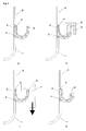
- Fig. 1 a shows a lateral view of a plastic part 1 which is in the shape of a sheet, and which has a recess formed by a U-shaped plastic joining part 2.
- the U-shaped plastic joining part 2 is laterally defined by two legs 3,3'.
- the J-shaped metal joining part 4 of a metal part 5, which is in the shape of a sheet as well, is inserted into the U-shaped plastic joining part 2.
- a heating element 6 is applied to heat leg 3' above the softening temperature of the plastic material.
- leg 3' while still having a temperature above its softening temperature is bent over the edge of metal joining part 4.
- the bending operation is performed with an appropriately shaped tool 7, which, as in the case of Fig. 1c, allows the bending operation to be performed by a simple downward motion of the tool 7.
- Fig. 1d shows the finished joining after the bending operation has been completed and the material has been allowed to cool and solidify.
- leg 3' is chosen longer than in Fig.1, which results in a substantial larger overlap of the finally bent leg 3' and the J-shaped metal joining part 4.
- Fig. 2 shows a basic embodiment of the invention, where the plastics joining part 8 comprises a simple flap.
- the metal joining part 9 of the metal part 19 is bent at an angle. Since the non-linear configuration of the metal joining 9 part is essential to the mechanical stability of the final joining, the angle is preferably not smaller than 30°.
- both the metal joining part 11 of the metal part 20 and the plastic joining part 10 are L-shaped.
- “Leg 12" is not an actual leg and is not laterally accessible as is leg 12'.
- Leg 12 is part of the body of the plastic part 13, which may e.g. be an injection moulded part.
- Fig. 4 shows an example of a metal joining part 14, which is branched.
- the metal joining part 14 of the metal part 21 is in the shape of an upside down Y. Accordingly, the plastic joining part 15 is W-shaped with both legs 16 being laterally accessible.
- the plastic parts 1,17,13,18 of Fig. 1-4 are obtained by injection molding, which allows the plastic joining parts 2,8,10,15 to be formed during the injection molding process. It is however also possible to obtain suitable plastic joining parts by other processes, e.g. extrusion (e.g. Fig.2) or mechanical finishing of an injection moulded part.
Landscapes
- Engineering & Computer Science (AREA)
- Mechanical Engineering (AREA)
- Lining Or Joining Of Plastics Or The Like (AREA)
- Connection Of Plates (AREA)
- Piezo-Electric Or Mechanical Vibrators, Or Delay Or Filter Circuits (AREA)
- Standing Axle, Rod, Or Tube Structures Coupled By Welding, Adhesion, Or Deposition (AREA)
- Shaping Of Tube Ends By Bending Or Straightening (AREA)
Abstract
Description
- The present invention relates to a novel joining technology for joining metal parts with plastic parts.
- Hybrid components from plastics-metal-composite are increasingly applied by the industry in applications where a number of functionalities must be realised. These components are incorporating the advantages of each of the basic materials and also the respective processing technologies. Composite structures can already be produced in the moulding process, but can also be produced after the moulding process by subsequent jointing.
- The present invention relates to a novel joining technology for joining metal parts with plastic parts which obviates the need for separate joining elements like screws, bolts, rivets, etc.
- Plastics and metal structures can be joined by a number of diverse joining techniques. Examples are positive substance jointing by e.g. glueing or injection moulding around metal inserts (the latter being a development by Bayer for automobile front ends). Further examples comprise mechanical joining techniques. Mechanical joining techniques are using either separate joining elements (punch rivets, bolts, screws, blind rivets, etc.) or integrated elements (snap-fits, TOX®-joinings, hot rivets, Kragenfügen, etc.). Using separate joining elements is expensive because of the costs of the joining elements themselves and because of a more complicated handling.
- It is therefore the object of the invention to provide a process for producing plastics/metal hybrid structures, i.e. a process for joining plastics with metal part, which process obviates the need for separate joining elements.
- The above object is achieved by a process for joining a plastic part with a metal part, the metal part comprising a joining part which is to be joined with the joining part of a plastic part where the metal joining part is in the shape of a strip, sheet or plate and is further in a non-linear shape, the plastic joining part comprising at least one flap or leg, the flap or leg being heated above the softening temperature of the plastic and where the heated flap or leg is bent in order to make the plastic joining part enclose the metal joining part.
- The process according to the invention allows quick joining of plastic parts with metal parts with little personnel resources and with only little technical efforts.
- The term "plastic" as used herein encompasses all plastic materials, which can be shaped under the influence of heat, especially all thermoplastic polymers, e.g. polyolefins like polyethylene or polypropylene.
- In a most basic embodiment the plastic joining part comprises just one flap.
- In a preferred embodiment the plastics joining part comprises a recess for receiving the metal joining part. On two of its facing sides the recess is laterally defined by two legs. Preferably the recess is in an oblong shape with the two legs being on its long sides. Therefore, in a spatial view the recess may have the shape of e.g. a chute or groove with rounded or angular base. On its short sides the oblong recess preferably is open.
- At least one of the legs which are laterally defining two facing sides of the recess is accessible laterally from outside of the recess.The expressions "flap" and "leg", can be used synonymously in the context of this invention. While the word "flap" is preferred for the most basic embodiment of the invention, it is preferred to use "leg" in the context of the more sophisticated embodiments of the invention, where the at least one "leg" which is laterally accessible technically is a "flap" too.
- The second leg may be laterally accessible as well, e.g. when the plastic joining part is a U-shaped or Y-shaped frontal edge of a plastic plate.
- The second leg may however also be comprised of the bulk of a voluminous component, i.e. may not be a "leg" at all, e.g. a recess in the shape of a U- or V-shaped groove running in the face of a plastic plate parallel to its edge.
- The recess may be rounded or angular or both rounded and angular. It may be U-shaped or V-shaped. Different shapes are possible as well, e.g. W-, Y-, J-, hook- or L-shaped.
- The metal joining part which is to be joined with the plastic joining part is in the shape of a strip, sheet or plate.
- It is an essential aspect of the invention, that the metal joining part is in a non-linear shape. "Non-linear" as used above in the context of the invention means, that the strip-, sheet- or plate-like metal joining part may be bent at an angle or curved or both bent and curved, e.g. J-, hook- or L-shaped. "Non-linear" may further mean, that the metal joining part is branched, e.g. T- or arrow- or Y-shaped.
- Preferably the metal joining part is shaped to fit into the recess of the plastic joining part.
- For this it is preferred that the metal joining part has an exterior contour which - more or less exactly - fits the interior contour of the recess. At least the at least one leg of the plastic joining part, which is laterally accessible, exceeds the edge of the metal joining part. Therefore, when that one leg of the plastic joining part is heated above its softening temperature, it can be bent around the edge of the metal joining part. This finally results in the plastic joining part enclosing the metal joining part.
- The connection between the metal and the plastic part according to the invention is stable and strong and resists all mechanical efforts for tearing it apart. It can only be broken, when the applied mechanical stress ist so large, that the material itself breaks or ruptures. It is a further advantage of the present process, that the joinings resulting from it are not susceptible to warpage. It is therefore possible to produce the metal part and also the plastics part with narrow tolerances. With proper choice of the plastic joining part and the metal joining part it is even possible to achieve gas-tight connections.
- Examples for corresponding shapes of metal joining part and plastic joining part are:
- e.g. metal joining part with a curved edge: J-shape for the metal joining part - the plastic joining part is U-shaped or J-shaped as well.
- e.g. edge of metal joining part is bent in a specific angle: L-shape for the metal joining part - the plastic joining part is U-shaped with an angular base or L-shaped as well.
- V-shape for the metal joining part - the plastic joining part is Y-shaped or is V-shaped as well.
- e.g. metal joining part is branched: T-shape (upside-down "T") for the metal joining part - the plastic joining part is U-shaped with both legs being laterally accessible.
- arrow-shape for the metal joining part - the plastic joining part is V-shaped.
- Y-shape (upside-down "Y") of the metal joining part - the plastic joining part is W-shaped.
- In all three examples above where the metal joining part is branched, it is preferred that both legs of the plastic joining part are laterally accessible. This ensures that the connection, which results from bending the heated and softened legs over both branches of the metal joining part, has optimum strength.
-
- A preferred application of the inventive process is in the production of interior casings of dishwashers. For the production of these interior casings it is necessary to connect metal sheets with plastic sheets along their edges. According to the prior art these connections have been produced with glueing and/or rivets. Connections obtained with glue are however not resistant to the permanent stress caused by hot/cold and detergent-containing water and connections produced with rivets are not splash proof. Both types of connections are difficult and expensive to produce.
- Connections produced with the process according to the invention are resistant to the thermally alternating stress and to the chemical stress caused by hot/cold and detergent-containing water which is typical for dishwashers. Connections produced with the process according to the invention are also splash-proof, therefore the danger of leakage is eliminated.
- The process according to the invention is illustrated in the drawings of Fig. 1. Further examples of connections which can be produced with the process according to the invention are shown in Fig. 2 to Fig. 4.
- Fig. 1 a shows a lateral view of a
plastic part 1 which is in the shape of a sheet, and which has a recess formed by a U-shapedplastic joining part 2. The U-shapedplastic joining part 2 is laterally defined by twolegs 3,3'. The J-shapedmetal joining part 4 of ametal part 5, which is in the shape of a sheet as well, is inserted into the U-shapedplastic joining part 2. - In Fig. 1
b a heating element 6 is applied to heat leg 3' above the softening temperature of the plastic material. - In Fig. 1c leg 3', while still having a temperature above its softening temperature is bent over the edge of
metal joining part 4. Preferably the bending operation is performed with an appropriately shapedtool 7, which, as in the case of Fig. 1c, allows the bending operation to be performed by a simple downward motion of thetool 7. - Fig. 1d shows the finished joining after the bending operation has been completed and the material has been allowed to cool and solidify.
- In an embodiment which is not shown in the Figures, leg 3' is chosen longer than in Fig.1, which results in a substantial larger overlap of the finally bent leg 3' and the J-shaped
metal joining part 4. - Fig. 2 shows a basic embodiment of the invention, where the
plastics joining part 8 comprises a simple flap. Themetal joining part 9 of themetal part 19 is bent at an angle. Since the non-linear configuration of the metal joining 9 part is essential to the mechanical stability of the final joining, the angle is preferably not smaller than 30°. - In Fig. 3 both the
metal joining part 11 of themetal part 20 and theplastic joining part 10 are L-shaped. "Leg 12" is not an actual leg and is not laterally accessible as is leg 12'.Leg 12 is part of the body of theplastic part 13, which may e.g. be an injection moulded part. - Fig. 4 shows an example of a
metal joining part 14, which is branched. In Fig. 4 themetal joining part 14 of themetal part 21 is in the shape of an upside down Y. Accordingly, theplastic joining part 15 is W-shaped with bothlegs 16 being laterally accessible. - Preferably the
plastic parts plastic joining parts
Claims (4)
- Process for joining a plastic part (1,17,13,18) with a metal part (5,19,20,21) the metal part comprising a joining part (4,9,11,14) which is to be joined with the joining part (2,8,10,15) of the plastic part (1,17,13,18) where the metal joining part (4,9,11,14) is in the shape of a strip, sheet or plate and is further in a non-linear shape, the plastic joining part (2,8,10,15) comprising at least one flap or leg (3,8,12,16), the flap or leg (3,8,12,16) being heated above the softening temperature of the plastic and where the heated flap or leg (3,8,12,16) is bent in order to make the plastic joining part (2,8,10,15) enclose the metal joining part (4,9,11,14).
- Process according to claim 1, characterised in that the plastic joining part (2,8,10,15) comprises a recess for receiving the metal joining part (4,9,11,14), where two facing sides of the recess are laterally defined by two legs (3,3',12,12',16).
- Process according to claim 2, characterised in that at least one of the legs (3',12',16) which are defining two facing sides of the recess is accessible laterally from outside of the recess.
- Process according to one of claims 2 or 3, characterised in that the metal joining part is branched (4,9,11,14).
Priority Applications (4)
| Application Number | Priority Date | Filing Date | Title |
|---|---|---|---|
| EP04005885A EP1574321B1 (en) | 2004-03-12 | 2004-03-12 | Process for joining by bending plastic/metal parts without separate joining elements |
| DE602004001850T DE602004001850T2 (en) | 2004-03-12 | 2004-03-12 | Method for joining by bending plastic and metal parts without further connecting elements |
| PL04005885T PL1574321T3 (en) | 2004-03-12 | 2004-03-12 | Process for joining by bending plastic/metal parts without separate joining elements |
| AT04005885T ATE335588T1 (en) | 2004-03-12 | 2004-03-12 | METHOD FOR CONNECTING BY BENDING PLASTIC AND METAL PARTS WITHOUT OTHER CONNECTING ELEMENTS |
Applications Claiming Priority (1)
| Application Number | Priority Date | Filing Date | Title |
|---|---|---|---|
| EP04005885A EP1574321B1 (en) | 2004-03-12 | 2004-03-12 | Process for joining by bending plastic/metal parts without separate joining elements |
Publications (2)
| Publication Number | Publication Date |
|---|---|
| EP1574321A1 true EP1574321A1 (en) | 2005-09-14 |
| EP1574321B1 EP1574321B1 (en) | 2006-08-09 |
Family
ID=34814305
Family Applications (1)
| Application Number | Title | Priority Date | Filing Date |
|---|---|---|---|
| EP04005885A Expired - Lifetime EP1574321B1 (en) | 2004-03-12 | 2004-03-12 | Process for joining by bending plastic/metal parts without separate joining elements |
Country Status (4)
| Country | Link |
|---|---|
| EP (1) | EP1574321B1 (en) |
| AT (1) | ATE335588T1 (en) |
| DE (1) | DE602004001850T2 (en) |
| PL (1) | PL1574321T3 (en) |
Cited By (1)
| Publication number | Priority date | Publication date | Assignee | Title |
|---|---|---|---|---|
| CN114096754A (en) * | 2019-06-28 | 2022-02-25 | 格兰富控股联合股份公司 | Electric pump device with shielded motor |
Citations (5)
| Publication number | Priority date | Publication date | Assignee | Title |
|---|---|---|---|---|
| FR1189896A (en) * | 1955-12-19 | 1959-10-07 | Tuboplast | Method for fixing a metallic element on one end of a container made of thermoplastic material and metallic element for the implementation of this method |
| US3524568A (en) * | 1967-04-11 | 1970-08-18 | Star Stabilimento Alimentare | Package for foodstuffs |
| US4854992A (en) * | 1987-04-24 | 1989-08-08 | Schott Glaswerke | Method for mounting an armature of plastic material to a jar of frangible material |
| EP0340094A2 (en) * | 1988-04-27 | 1989-11-02 | Automobiles Peugeot | Process for joining by riveting a first part made of plastic to a second part. |
| DE20112720U1 (en) * | 2000-08-16 | 2001-11-15 | Österreichische Blechwarenfabrik Pirlo Ges.m.b.H. & Co., Kufstein | Compound box |
-
2004
- 2004-03-12 EP EP04005885A patent/EP1574321B1/en not_active Expired - Lifetime
- 2004-03-12 AT AT04005885T patent/ATE335588T1/en not_active IP Right Cessation
- 2004-03-12 DE DE602004001850T patent/DE602004001850T2/en not_active Expired - Lifetime
- 2004-03-12 PL PL04005885T patent/PL1574321T3/en unknown
Patent Citations (5)
| Publication number | Priority date | Publication date | Assignee | Title |
|---|---|---|---|---|
| FR1189896A (en) * | 1955-12-19 | 1959-10-07 | Tuboplast | Method for fixing a metallic element on one end of a container made of thermoplastic material and metallic element for the implementation of this method |
| US3524568A (en) * | 1967-04-11 | 1970-08-18 | Star Stabilimento Alimentare | Package for foodstuffs |
| US4854992A (en) * | 1987-04-24 | 1989-08-08 | Schott Glaswerke | Method for mounting an armature of plastic material to a jar of frangible material |
| EP0340094A2 (en) * | 1988-04-27 | 1989-11-02 | Automobiles Peugeot | Process for joining by riveting a first part made of plastic to a second part. |
| DE20112720U1 (en) * | 2000-08-16 | 2001-11-15 | Österreichische Blechwarenfabrik Pirlo Ges.m.b.H. & Co., Kufstein | Compound box |
Cited By (2)
| Publication number | Priority date | Publication date | Assignee | Title |
|---|---|---|---|---|
| CN114096754A (en) * | 2019-06-28 | 2022-02-25 | 格兰富控股联合股份公司 | Electric pump device with shielded motor |
| CN114096754B (en) * | 2019-06-28 | 2024-02-13 | 格兰富控股联合股份公司 | Electric pump device with shielded motor |
Also Published As
| Publication number | Publication date |
|---|---|
| ATE335588T1 (en) | 2006-09-15 |
| DE602004001850D1 (en) | 2006-09-21 |
| PL1574321T3 (en) | 2006-12-29 |
| DE602004001850T2 (en) | 2007-02-08 |
| EP1574321B1 (en) | 2006-08-09 |
Similar Documents
| Publication | Publication Date | Title |
|---|---|---|
| US7117578B2 (en) | Process for producing a composite component | |
| CN103097190B (en) | Method for producing rear wall of seat back | |
| US20040194281A1 (en) | Composite part and method for the production thereof | |
| KR20140092919A (en) | Method for producing a structural component, device for carrying out the method and structural component | |
| GB2564927A (en) | Stiffening structure for an aircraft door or panel | |
| EP1574321B1 (en) | Process for joining by bending plastic/metal parts without separate joining elements | |
| US20150118453A1 (en) | Method for connecting thermoplastic, coated components and plastic component | |
| US20080110549A1 (en) | Internal perimeter molding method and related article | |
| JP6942150B2 (en) | Thermoformed parts with adherent parts and the process of manufacturing such parts | |
| JP2006524158A (en) | Hollow composite cavity parts | |
| US20200086550A1 (en) | Fastenerless structural assembly | |
| GB2564928A (en) | Door assembly for a vehicle | |
| GB2564753A (en) | Fastenerless structural assembly | |
| CN206468967U (en) | Pre- catheter device | |
| US10821639B2 (en) | Multi-material conveyor component | |
| JP3590771B2 (en) | Blow molded article having welding flange | |
| JPS581518A (en) | Preparation of vacuum molded parts | |
| CN112549557A (en) | Method for producing metal-plastic hybrid component, and metal-plastic hybrid component | |
| US20120006831A1 (en) | Manufacturing method for foam molded article and packaging material | |
| CN109910274B (en) | Metal and thermoplastic composite bonding and reshaping method | |
| EP3403918A1 (en) | Stiffening structure for an aircraft door or panel | |
| KR100875190B1 (en) | Manufacturing method of vacuum molded article | |
| EP2803472A2 (en) | Laminar structures and methods of producing the same | |
| JPH0999483A (en) | Molding equipment for synthetic resin hollow molding | |
| JPS58217318A (en) | Flash processing on cut surface of synthetic resin article |
Legal Events
| Date | Code | Title | Description |
|---|---|---|---|
| PUAI | Public reference made under article 153(3) epc to a published international application that has entered the european phase |
Free format text: ORIGINAL CODE: 0009012 |
|
| AK | Designated contracting states |
Kind code of ref document: A1 Designated state(s): AT BE BG CH CY CZ DE DK EE ES FI FR GB GR HU IE IT LI LU MC NL PL PT RO SE SI SK TR |
|
| AX | Request for extension of the european patent |
Extension state: AL LT LV MK |
|
| 17P | Request for examination filed |
Effective date: 20060124 |
|
| GRAP | Despatch of communication of intention to grant a patent |
Free format text: ORIGINAL CODE: EPIDOSNIGR1 |
|
| AKX | Designation fees paid |
Designated state(s): AT BE BG CH CY CZ DE DK EE ES FI FR GB GR HU IE IT LI LU MC NL PL PT RO SE SI SK TR |
|
| GRAS | Grant fee paid |
Free format text: ORIGINAL CODE: EPIDOSNIGR3 |
|
| GRAA | (expected) grant |
Free format text: ORIGINAL CODE: 0009210 |
|
| AK | Designated contracting states |
Kind code of ref document: B1 Designated state(s): AT BE BG CH CY CZ DE DK EE ES FI FR GB GR HU IE IT LI LU MC NL PL PT RO SE SI SK TR |
|
| PG25 | Lapsed in a contracting state [announced via postgrant information from national office to epo] |
Ref country code: IT Free format text: LAPSE BECAUSE OF FAILURE TO SUBMIT A TRANSLATION OF THE DESCRIPTION OR TO PAY THE FEE WITHIN THE PRESCRIBED TIME-LIMIT;WARNING: LAPSES OF ITALIAN PATENTS WITH EFFECTIVE DATE BEFORE 2007 MAY HAVE OCCURRED AT ANY TIME BEFORE 2007. THE CORRECT EFFECTIVE DATE MAY BE DIFFERENT FROM THE ONE RECORDED. Effective date: 20060809 Ref country code: SI Free format text: LAPSE BECAUSE OF FAILURE TO SUBMIT A TRANSLATION OF THE DESCRIPTION OR TO PAY THE FEE WITHIN THE PRESCRIBED TIME-LIMIT Effective date: 20060809 Ref country code: BE Free format text: LAPSE BECAUSE OF FAILURE TO SUBMIT A TRANSLATION OF THE DESCRIPTION OR TO PAY THE FEE WITHIN THE PRESCRIBED TIME-LIMIT Effective date: 20060809 Ref country code: AT Free format text: LAPSE BECAUSE OF FAILURE TO SUBMIT A TRANSLATION OF THE DESCRIPTION OR TO PAY THE FEE WITHIN THE PRESCRIBED TIME-LIMIT Effective date: 20060809 Ref country code: FI Free format text: LAPSE BECAUSE OF FAILURE TO SUBMIT A TRANSLATION OF THE DESCRIPTION OR TO PAY THE FEE WITHIN THE PRESCRIBED TIME-LIMIT Effective date: 20060809 Ref country code: LI Free format text: LAPSE BECAUSE OF FAILURE TO SUBMIT A TRANSLATION OF THE DESCRIPTION OR TO PAY THE FEE WITHIN THE PRESCRIBED TIME-LIMIT Effective date: 20060809 Ref country code: NL Free format text: LAPSE BECAUSE OF FAILURE TO SUBMIT A TRANSLATION OF THE DESCRIPTION OR TO PAY THE FEE WITHIN THE PRESCRIBED TIME-LIMIT Effective date: 20060809 Ref country code: RO Free format text: LAPSE BECAUSE OF FAILURE TO SUBMIT A TRANSLATION OF THE DESCRIPTION OR TO PAY THE FEE WITHIN THE PRESCRIBED TIME-LIMIT Effective date: 20060809 Ref country code: CH Free format text: LAPSE BECAUSE OF FAILURE TO SUBMIT A TRANSLATION OF THE DESCRIPTION OR TO PAY THE FEE WITHIN THE PRESCRIBED TIME-LIMIT Effective date: 20060809 Ref country code: CZ Free format text: LAPSE BECAUSE OF FAILURE TO SUBMIT A TRANSLATION OF THE DESCRIPTION OR TO PAY THE FEE WITHIN THE PRESCRIBED TIME-LIMIT Effective date: 20060809 |
|
| REG | Reference to a national code |
Ref country code: GB Ref legal event code: FG4D |
|
| REG | Reference to a national code |
Ref country code: CH Ref legal event code: EP |
|
| REG | Reference to a national code |
Ref country code: IE Ref legal event code: FG4D |
|
| REF | Corresponds to: |
Ref document number: 602004001850 Country of ref document: DE Date of ref document: 20060921 Kind code of ref document: P |
|
| PG25 | Lapsed in a contracting state [announced via postgrant information from national office to epo] |
Ref country code: BG Free format text: LAPSE BECAUSE OF FAILURE TO SUBMIT A TRANSLATION OF THE DESCRIPTION OR TO PAY THE FEE WITHIN THE PRESCRIBED TIME-LIMIT Effective date: 20061109 Ref country code: SE Free format text: LAPSE BECAUSE OF FAILURE TO SUBMIT A TRANSLATION OF THE DESCRIPTION OR TO PAY THE FEE WITHIN THE PRESCRIBED TIME-LIMIT Effective date: 20061109 Ref country code: DK Free format text: LAPSE BECAUSE OF FAILURE TO SUBMIT A TRANSLATION OF THE DESCRIPTION OR TO PAY THE FEE WITHIN THE PRESCRIBED TIME-LIMIT Effective date: 20061109 |
|
| PG25 | Lapsed in a contracting state [announced via postgrant information from national office to epo] |
Ref country code: ES Free format text: LAPSE BECAUSE OF FAILURE TO SUBMIT A TRANSLATION OF THE DESCRIPTION OR TO PAY THE FEE WITHIN THE PRESCRIBED TIME-LIMIT Effective date: 20061120 |
|
| PG25 | Lapsed in a contracting state [announced via postgrant information from national office to epo] |
Ref country code: PT Free format text: LAPSE BECAUSE OF FAILURE TO SUBMIT A TRANSLATION OF THE DESCRIPTION OR TO PAY THE FEE WITHIN THE PRESCRIBED TIME-LIMIT Effective date: 20070109 |
|
| NLV1 | Nl: lapsed or annulled due to failure to fulfill the requirements of art. 29p and 29m of the patents act | ||
| REG | Reference to a national code |
Ref country code: CH Ref legal event code: PL |
|
| ET | Fr: translation filed | ||
| PLBE | No opposition filed within time limit |
Free format text: ORIGINAL CODE: 0009261 |
|
| STAA | Information on the status of an ep patent application or granted ep patent |
Free format text: STATUS: NO OPPOSITION FILED WITHIN TIME LIMIT |
|
| 26N | No opposition filed |
Effective date: 20070510 |
|
| PG25 | Lapsed in a contracting state [announced via postgrant information from national office to epo] |
Ref country code: MC Free format text: LAPSE BECAUSE OF NON-PAYMENT OF DUE FEES Effective date: 20070331 Ref country code: IE Free format text: LAPSE BECAUSE OF NON-PAYMENT OF DUE FEES Effective date: 20070312 |
|
| PG25 | Lapsed in a contracting state [announced via postgrant information from national office to epo] |
Ref country code: GR Free format text: LAPSE BECAUSE OF FAILURE TO SUBMIT A TRANSLATION OF THE DESCRIPTION OR TO PAY THE FEE WITHIN THE PRESCRIBED TIME-LIMIT Effective date: 20061110 |
|
| PG25 | Lapsed in a contracting state [announced via postgrant information from national office to epo] |
Ref country code: EE Free format text: LAPSE BECAUSE OF FAILURE TO SUBMIT A TRANSLATION OF THE DESCRIPTION OR TO PAY THE FEE WITHIN THE PRESCRIBED TIME-LIMIT Effective date: 20060809 |
|
| PG25 | Lapsed in a contracting state [announced via postgrant information from national office to epo] |
Ref country code: CY Free format text: LAPSE BECAUSE OF FAILURE TO SUBMIT A TRANSLATION OF THE DESCRIPTION OR TO PAY THE FEE WITHIN THE PRESCRIBED TIME-LIMIT Effective date: 20060809 Ref country code: LU Free format text: LAPSE BECAUSE OF NON-PAYMENT OF DUE FEES Effective date: 20070312 |
|
| PG25 | Lapsed in a contracting state [announced via postgrant information from national office to epo] |
Ref country code: TR Free format text: LAPSE BECAUSE OF FAILURE TO SUBMIT A TRANSLATION OF THE DESCRIPTION OR TO PAY THE FEE WITHIN THE PRESCRIBED TIME-LIMIT Effective date: 20060809 Ref country code: HU Free format text: LAPSE BECAUSE OF FAILURE TO SUBMIT A TRANSLATION OF THE DESCRIPTION OR TO PAY THE FEE WITHIN THE PRESCRIBED TIME-LIMIT Effective date: 20070210 |
|
| PGFP | Annual fee paid to national office [announced via postgrant information from national office to epo] |
Ref country code: FR Payment date: 20120403 Year of fee payment: 9 |
|
| PGFP | Annual fee paid to national office [announced via postgrant information from national office to epo] |
Ref country code: GB Payment date: 20120322 Year of fee payment: 9 |
|
| GBPC | Gb: european patent ceased through non-payment of renewal fee |
Effective date: 20130312 |
|
| REG | Reference to a national code |
Ref country code: FR Ref legal event code: ST Effective date: 20131129 |
|
| PG25 | Lapsed in a contracting state [announced via postgrant information from national office to epo] |
Ref country code: GB Free format text: LAPSE BECAUSE OF NON-PAYMENT OF DUE FEES Effective date: 20130312 Ref country code: FR Free format text: LAPSE BECAUSE OF NON-PAYMENT OF DUE FEES Effective date: 20130402 |
|
| PGFP | Annual fee paid to national office [announced via postgrant information from national office to epo] |
Ref country code: DE Payment date: 20170322 Year of fee payment: 14 |
|
| PGFP | Annual fee paid to national office [announced via postgrant information from national office to epo] |
Ref country code: SK Payment date: 20170308 Year of fee payment: 14 |
|
| PGFP | Annual fee paid to national office [announced via postgrant information from national office to epo] |
Ref country code: IT Payment date: 20170323 Year of fee payment: 14 |
|
| PGFP | Annual fee paid to national office [announced via postgrant information from national office to epo] |
Ref country code: PL Payment date: 20170309 Year of fee payment: 14 |
|
| REG | Reference to a national code |
Ref country code: DE Ref legal event code: R119 Ref document number: 602004001850 Country of ref document: DE |
|
| REG | Reference to a national code |
Ref country code: SK Ref legal event code: MM4A Ref document number: E 1229 Country of ref document: SK Effective date: 20180312 |
|
| PG25 | Lapsed in a contracting state [announced via postgrant information from national office to epo] |
Ref country code: SK Free format text: LAPSE BECAUSE OF NON-PAYMENT OF DUE FEES Effective date: 20180312 Ref country code: DE Free format text: LAPSE BECAUSE OF NON-PAYMENT OF DUE FEES Effective date: 20181002 |
|
| PG25 | Lapsed in a contracting state [announced via postgrant information from national office to epo] |
Ref country code: IT Free format text: LAPSE BECAUSE OF NON-PAYMENT OF DUE FEES Effective date: 20180312 |
|
| PG25 | Lapsed in a contracting state [announced via postgrant information from national office to epo] |
Ref country code: PL Free format text: LAPSE BECAUSE OF NON-PAYMENT OF DUE FEES Effective date: 20180312 |