EP1574306B1 - Surface planer - Google Patents
Surface planer Download PDFInfo
- Publication number
- EP1574306B1 EP1574306B1 EP05012866A EP05012866A EP1574306B1 EP 1574306 B1 EP1574306 B1 EP 1574306B1 EP 05012866 A EP05012866 A EP 05012866A EP 05012866 A EP05012866 A EP 05012866A EP 1574306 B1 EP1574306 B1 EP 1574306B1
- Authority
- EP
- European Patent Office
- Prior art keywords
- speed
- stage
- cutter head
- feed rollers
- motor
- Prior art date
- Legal status (The legal status is an assumption and is not a legal conclusion. Google has not performed a legal analysis and makes no representation as to the accuracy of the status listed.)
- Expired - Lifetime
Links
- 230000005540 biological transmission Effects 0.000 claims abstract description 13
- 230000009977 dual effect Effects 0.000 claims abstract description 10
- 239000002023 wood Substances 0.000 description 4
- 230000001419 dependent effect Effects 0.000 description 1
- 238000004519 manufacturing process Methods 0.000 description 1
- 239000000463 material Substances 0.000 description 1
- 230000002093 peripheral effect Effects 0.000 description 1
Images

Classifications
-
- B—PERFORMING OPERATIONS; TRANSPORTING
- B27—WORKING OR PRESERVING WOOD OR SIMILAR MATERIAL; NAILING OR STAPLING MACHINES IN GENERAL
- B27C—PLANING, DRILLING, MILLING, TURNING OR UNIVERSAL MACHINES FOR WOOD OR SIMILAR MATERIAL
- B27C1/00—Machines for producing flat surfaces, e.g. by rotary cutters; Equipment therefor
- B27C1/04—Thicknessing machines
-
- B—PERFORMING OPERATIONS; TRANSPORTING
- B27—WORKING OR PRESERVING WOOD OR SIMILAR MATERIAL; NAILING OR STAPLING MACHINES IN GENERAL
- B27C—PLANING, DRILLING, MILLING, TURNING OR UNIVERSAL MACHINES FOR WOOD OR SIMILAR MATERIAL
- B27C1/00—Machines for producing flat surfaces, e.g. by rotary cutters; Equipment therefor
- B27C1/12—Arrangements for feeding work
-
- Y—GENERAL TAGGING OF NEW TECHNOLOGICAL DEVELOPMENTS; GENERAL TAGGING OF CROSS-SECTIONAL TECHNOLOGIES SPANNING OVER SEVERAL SECTIONS OF THE IPC; TECHNICAL SUBJECTS COVERED BY FORMER USPC CROSS-REFERENCE ART COLLECTIONS [XRACs] AND DIGESTS
- Y10—TECHNICAL SUBJECTS COVERED BY FORMER USPC
- Y10T—TECHNICAL SUBJECTS COVERED BY FORMER US CLASSIFICATION
- Y10T29/00—Metal working
- Y10T29/51—Plural diverse manufacturing apparatus including means for metal shaping or assembling
- Y10T29/5104—Type of machine
- Y10T29/5115—Planer
-
- Y—GENERAL TAGGING OF NEW TECHNOLOGICAL DEVELOPMENTS; GENERAL TAGGING OF CROSS-SECTIONAL TECHNOLOGIES SPANNING OVER SEVERAL SECTIONS OF THE IPC; TECHNICAL SUBJECTS COVERED BY FORMER USPC CROSS-REFERENCE ART COLLECTIONS [XRACs] AND DIGESTS
- Y10—TECHNICAL SUBJECTS COVERED BY FORMER USPC
- Y10T—TECHNICAL SUBJECTS COVERED BY FORMER US CLASSIFICATION
- Y10T74/00—Machine element or mechanism
- Y10T74/20—Control lever and linkage systems
- Y10T74/20012—Multiple controlled elements
- Y10T74/20018—Transmission control
-
- Y—GENERAL TAGGING OF NEW TECHNOLOGICAL DEVELOPMENTS; GENERAL TAGGING OF CROSS-SECTIONAL TECHNOLOGIES SPANNING OVER SEVERAL SECTIONS OF THE IPC; TECHNICAL SUBJECTS COVERED BY FORMER USPC CROSS-REFERENCE ART COLLECTIONS [XRACs] AND DIGESTS
- Y10—TECHNICAL SUBJECTS COVERED BY FORMER USPC
- Y10T—TECHNICAL SUBJECTS COVERED BY FORMER US CLASSIFICATION
- Y10T74/00—Machine element or mechanism
- Y10T74/20—Control lever and linkage systems
- Y10T74/20012—Multiple controlled elements
- Y10T74/20018—Transmission control
- Y10T74/2014—Manually operated selector [e.g., remotely controlled device, lever, push button, rotary dial, etc.]
-
- Y—GENERAL TAGGING OF NEW TECHNOLOGICAL DEVELOPMENTS; GENERAL TAGGING OF CROSS-SECTIONAL TECHNOLOGIES SPANNING OVER SEVERAL SECTIONS OF THE IPC; TECHNICAL SUBJECTS COVERED BY FORMER USPC CROSS-REFERENCE ART COLLECTIONS [XRACs] AND DIGESTS
- Y10—TECHNICAL SUBJECTS COVERED BY FORMER USPC
- Y10T—TECHNICAL SUBJECTS COVERED BY FORMER US CLASSIFICATION
- Y10T74/00—Machine element or mechanism
- Y10T74/20—Control lever and linkage systems
- Y10T74/20207—Multiple controlling elements for single controlled element
- Y10T74/20238—Interlocked
- Y10T74/20244—Push button
Definitions
- the present invention relates to surface planers having variable speed feed rollers according to the preamble of claim 1.
- Surface planers are most commonly provided with a pair of feed rollers one on the in feed and one on the out feed side of the rotary cutter head for moving a wooden board to be planed relative to the cutter head at a fixed speed.
- the only adjustment an operator typically has for taking a light or heavy cut is the position the cutter head is spaced from the support platen which determines the depth of cut.
- a very small incremental adjustment is made between the in planing passes.
- a relatively large in depth adjustment is made between planing passes so that the material is removed more quickly.
- U.S. Patent 3,718,168 assigned to Rockwell Manufacturing Company discloses a belt drive feed roller where the drive ratio can be varied by the operator using a variable diameter pulley system.
- U.S. Patent 4,440,204 assigned to Shopsmith, Inc. discloses a planer attachment for a multi-purpose tool which is provided with a separate variable speed drive motor for advancing the feed rollers. The speed of the feed rollers can be varied by the operator dependent upon the characteristics of the board to be planed.
- variable feed speed planers prior art tend to be bulky and expansive.
- a surface planer according to the preamble of claim 1 is known from EP-A-0 321 390.
- the object of the present invention is to make a simple robust low cost multi-speed surface planes.
- a surface planer of the present invention comprises the features of claim 1. It is provided with a motor having an output member, a rotary cutting head operatively connected to the motor output member and at least one feed roller positioned parallel to and adjacent the rotary cutter head for moving a wood board to be planed relative to the rotary cutting head.
- a multi-stage transmission is interposed between the motor and the feed roller.
- the multi-stage transmission has an input connected to the motor and an output drivingly connected to a feed roller.
- the multi-stage transmission has a dual speed stage provided with an operator's actuated speed selector element which when shifted between two positions, changes the final drive ratio resulting in a change in speed of the feed rollers.
- the dual speed stage is provided by a planetary gear set which preferably is the final stage and is remotely located from the remaining stages of the multi-stage transmission.
- the surface planer 10 of the present invention is schematically shown in horizontal side elevation planing in elongate wood board 12.
- the surface planer, 10 illustrated is a portable bench top type device, however, the present invention, is equally useful in a large stationary floor mounted tool.
- Surface planer 10 is made up of a frame 14 which includes a platen 16 for supporting the board that it is positioned thereupon and a series of columns 18 which extend vertically relative to the platen.
- the platen is fixed to frame and a motor cutter head assembly 20 is vertically positionable relative to the platen 16 by the operator upon rotation of handwheel 22 which is associated with a conventional screw drive height adjustment mechanism common in the art.
- motor cutter head assembly 20 can be fixed relative to the frame and handwheel 22 can raise and lower the platen as is also well known in the surface planer art.
- Motor cutter head assembly 20 is made up of a motor 24, a rotary cutter head 26, a pair of feed roller 28 and 30, respectively disposed on the infeed and outfeed side of the cutter head, and a first gearbox 32 which forms a multi-stage transmission having a reduced speed first gearbox output member 34.
- the first gearbox output member 34 is operatively connected to at least one of the feed rollers 28 and 30.
- motor 24 is operatively connected in driving relationship to cutter head 26.
- the surface planer of the present invention is specifically adapted to be fabricated as part of a family of high and low priced tools having maximum component part commonality.
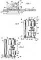
- a relatively low priced single feed speed surface planer 40 is illustrated in Figure 2, while the relatively higher priced dual speed surface planer 60 is illustrated in Figure 3.
- the only difference between one speed surface planer 40 and dual speed surface planer 60 is the connection between the first gearbox output member 34 and out feed roller 30.
- Single speed surface planer 40 illustrated in Figure 2 has a fixed diameter circular drive element, namely a sprocket 36, affixed to the distal end of first gearbox output member 34.
- Sprocket 36 is operatively connected to corresponding sprocket 38 on outfeed drive roller 30 which are operatively connected together by a flexible tensile member, chain 42 which extends thereabout.
- chain 42 which extends thereabout.
- outfeed drive roller and infeed drive roller 30 and 28 are interconnected so that they rotate in unison in the same direction.
- Out feed drive roller 30 is provided with a sprocket 44 and in feed drive roller 28 is provided with a sprocket 46 which are interconnected by a chain 48 which cause the rollers to rotate in unison at an identical speed.
- belts and pulleys can be substituted for sprockets and chains.
- Belts and pulleys can be of the smooth or cog variety.
- a pair of circular drive elements and a flexible tensile member interconnect motor 24 and cutter head 26. In the embodiment illustrated, this connection is achieved by sprocket 50 on the motor output shaft, sprocket 52 on the cutter head and chain 54 extending thereabout.
- illustrated motor 24 is the dual output shaft variety having an output shaft extending from both axial ends of the motor; one end is associated with the cutter head and the opposite end is associated with the first gearbox 32.
- Cutter head 26 and infeed and out feed rollers 28 and 30 are mounted relative to the frame portion of motor cutter head assembly 20 by a series of conventional roller bearings illustrated.
- Two speed surface planer 60 illustrated in Figure 3 differs from the one speed surface planer 40 illustrated in Figure 2 in one area.
- a second gearbox 62 is affixed to the shaft, as illustrated in Figure 3.
- An enlarged cross-sectional view of second gearbox 62 is provided in Figures 4 and 5.
- Second gearbox 62 is provided with an input member 64 which is affixed to and rotates with first gearbox output member 34, and output member 66 which includes a sprocket 68 and a speed selector element 70 which is shiftable between a high speed position illustrated in Figure 4 and a low speed position illustrated in Figure 5.
- the embodiment of the second gearbox illustrated utilizes a planetary gear set to change the final drive ratio between input member 64 and output member 66.
- speed selector element 70 When speed selector element 70 is in the high speed position illustrated in Figure 4, the output member and input member 66 and 64 rotate in unison.
- speed selector element 70 When speed selector element 70 is moved to the low speed position as shown in Figure 5, output member 66 rotates at approximately half the speed of input member 64.
- Speed reduction is achieved by a planetary gear set made up of a ring gear 72 which is affixed to the output member 66, sun gear 74 is fixed relative to frame 14, and a planet carrier 76 and associated planet gears 78 and 80.
- a collar member 82 is affixed to and rotates with planet carrier 76.
- Collar 82 is provided with an internally splined bore 84 which is sized to engage the splined exterior surface 86 about the periphery of speed selector element 70.
- the internal bore of speed selector element 70 is provided with two spaced apart internally splined regions 86 and 88. Splined region 86 slidingly engages the splined outer periphery of output member 66 to cause the output member 66 and the speed selector element 70 to always rotate in unison.
- Spline region 88 on the interior of speed selector element 70 alternatively engages or disengages splined outer peripheral segment 90 with input member 64.
- a coil spring 96 will be provided to bias the speed selector element 70 to one of the two speed states.
- spring 96 biases speed selector element 70 to the high speed position shown in Figure 4.
- a conventional detent not shown, will be provided on the knob and fork assembly 94 to retain speed selector element 70 in the low speed mode, when the knob is shifted to the low speed position by the operator.
- the planetary gear arrangement enables the second gearbox 62 to made quite compact and readily interchangeable with sprocket 36 without varying the location of sprocket 36 with that of a sprocket 68 on the second gearbox.
- second gearbox 62 is remotely located and distinct from the first gearbox 32.
- the first gearbox 32 has three gear reduction stages accomplished by three pairs of gears oriented on two intermediate shafts, the input shaft of the motor and the first gearbox output member as illustrated in Figures 2 and 3. While a three stage gear reduction is used in the preferred embodiment, a two or a four stage gear reduction in the first gearbox can alternatively be used.
Landscapes
- Life Sciences & Earth Sciences (AREA)
- Engineering & Computer Science (AREA)
- Mechanical Engineering (AREA)
- Wood Science & Technology (AREA)
- Forests & Forestry (AREA)
- Milling, Drilling, And Turning Of Wood (AREA)
- Fuel Cell (AREA)
- Gears, Cams (AREA)
- Chemical And Physical Treatments For Wood And The Like (AREA)
- Joints Allowing Movement (AREA)
- Sealing Devices (AREA)
- Orthopedics, Nursing, And Contraception (AREA)
Abstract
Description
- The present invention relates to surface planers having variable speed feed rollers according to the preamble of claim 1.
- Surface planers are most commonly provided with a pair of feed rollers one on the in feed and one on the out feed side of the rotary cutter head for moving a wooden board to be planed relative to the cutter head at a fixed speed. The only adjustment an operator typically has for taking a light or heavy cut is the position the cutter head is spaced from the support platen which determines the depth of cut. When it is desired to take a light cut, a very small incremental adjustment is made between the in planing passes. When it is desired to make a rough cut, a relatively large in depth adjustment is made between planing passes so that the material is removed more quickly.
- There have been limited efforts in the past to infinitely vary the speed of the board to be planed relative to the cutter head. U.S. Patent 3,718,168 assigned to Rockwell Manufacturing Company, discloses a belt drive feed roller where the drive ratio can be varied by the operator using a variable diameter pulley system. U.S. Patent 4,440,204 assigned to Shopsmith, Inc., discloses a planer attachment for a multi-purpose tool which is provided with a separate variable speed drive motor for advancing the feed rollers. The speed of the feed rollers can be varied by the operator dependent upon the characteristics of the board to be planed.
- The variable feed speed planers prior art tend to be bulky and expansive.
- A surface planer according to the preamble of claim 1 is known from EP-A-0 321 390.
- The object of the present invention is to make a simple robust low cost multi-speed surface planes.
- A surface planer of the present invention comprises the features of claim 1. It is provided with a motor having an output member, a rotary cutting head operatively connected to the motor output member and at least one feed roller positioned parallel to and adjacent the rotary cutter head for moving a wood board to be planed relative to the rotary cutting head. A multi-stage transmission is interposed between the motor and the feed roller. The multi-stage transmission has an input connected to the motor and an output drivingly connected to a feed roller. The multi-stage transmission has a dual speed stage provided with an operator's actuated speed selector element which when shifted between two positions, changes the final drive ratio resulting in a change in speed of the feed rollers.
- The dual speed stage is provided by a planetary gear set which preferably is the final stage and is remotely located from the remaining stages of the multi-stage transmission.
-
- FIGURE 1 is a perspective view of a Surface Planer of the present invention;
- FIGURE 2 is a top plan schematic view of a single speed Surface Planer;
- FIGURE 3 is a top plan schematic view of a dual speed Surface Planer;
- FIGURE 4 is a crossectional view of the gear box in the high speed mode;
- FIGURE 5 is a crossectional view of the gear box in the low speed mode; and
- FIGURE 6 is a crossection of the sprocket member used in the single speed mode.
- The
surface planer 10 of the present invention is schematically shown in horizontal side elevation planing inelongate wood board 12. The surface planer, 10 illustrated, is a portable bench top type device, however, the present invention, is equally useful in a large stationary floor mounted tool.Surface planer 10 is made up of aframe 14 which includes aplaten 16 for supporting the board that it is positioned thereupon and a series ofcolumns 18 which extend vertically relative to the platen. In thesurface planer embodiment 10 illustrated, the platen is fixed to frame and a motorcutter head assembly 20 is vertically positionable relative to theplaten 16 by the operator upon rotation ofhandwheel 22 which is associated with a conventional screw drive height adjustment mechanism common in the art. Alternatively, the motorcutter head assembly 20 can be fixed relative to the frame andhandwheel 22 can raise and lower the platen as is also well known in the surface planer art. Motorcutter head assembly 20 is made up of amotor 24, arotary cutter head 26, a pair offeed roller first gearbox 32 which forms a multi-stage transmission having a reduced speed firstgearbox output member 34. The firstgearbox output member 34 is operatively connected to at least one of thefeed rollers motor 24 is operatively connected in driving relationship tocutter head 26. When the motor is turned on and running at its operating speed, the feed rollers are rotating in a first direction, causing the wood to move into and through the planer while the cutter head will be rotates in an opposite direction as illustrated in Figure 1, so that the blades on thecutter head 26 cuts against the direction of theincoming wood board 12. - The surface planer of the present invention is specifically adapted to be fabricated as part of a family of high and low priced tools having maximum component part commonality. A relatively low priced single feed
speed surface planer 40 is illustrated in Figure 2, while the relatively higher priced dualspeed surface planer 60 is illustrated in Figure 3. The only difference between onespeed surface planer 40 and dualspeed surface planer 60 is the connection between the firstgearbox output member 34 and outfeed roller 30. - Single
speed surface planer 40 illustrated in Figure 2, has a fixed diameter circular drive element, namely asprocket 36, affixed to the distal end of firstgearbox output member 34. Sprocket 36 is operatively connected tocorresponding sprocket 38 on outfeeddrive roller 30 which are operatively connected together by a flexible tensile member,chain 42 which extends thereabout. Of course, rather than using sprockets and chains, belts and pulleys could be utilized. In the two embodiments illustrated, outfeed drive roller and infeeddrive roller feed drive roller 30 is provided with asprocket 44 and infeed drive roller 28 is provided with asprocket 46 which are interconnected by achain 48 which cause the rollers to rotate in unison at an identical speed. Once again, belts and pulleys can be substituted for sprockets and chains. Belts and pulleys can be of the smooth or cog variety. Similarly, a pair of circular drive elements and a flexible tensile member interconnectmotor 24 andcutter head 26. In the embodiment illustrated, this connection is achieved bysprocket 50 on the motor output shaft, sprocket 52 on the cutter head andchain 54 extending thereabout. - In the preferred embodiment, illustrated
motor 24 is the dual output shaft variety having an output shaft extending from both axial ends of the motor; one end is associated with the cutter head and the opposite end is associated with thefirst gearbox 32.Cutter head 26 and infeed and outfeed rollers cutter head assembly 20 by a series of conventional roller bearings illustrated. - Two
speed surface planer 60 illustrated in Figure 3, differs from the onespeed surface planer 40 illustrated in Figure 2 in one area. Rather than having asprocket 36 on a the distal end of firstgearbox output member 34 , a second gearbox 62 is affixed to the shaft, as illustrated in Figure 3. An enlarged cross-sectional view of second gearbox 62 is provided in Figures 4 and 5. A corresponding in enlarged cross-sectional view ofsprocket 36 mounted on the distal end of firstgearbox output member 34 as illustrated in Figure 6. Second gearbox 62 is provided with aninput member 64 which is affixed to and rotates with firstgearbox output member 34, andoutput member 66 which includes asprocket 68 and aspeed selector element 70 which is shiftable between a high speed position illustrated in Figure 4 and a low speed position illustrated in Figure 5. - The embodiment of the second gearbox illustrated utilizes a planetary gear set to change the final drive ratio between
input member 64 andoutput member 66. Whenspeed selector element 70 is in the high speed position illustrated in Figure 4, the output member andinput member speed selector element 70 is moved to the low speed position as shown in Figure 5,output member 66 rotates at approximately half the speed ofinput member 64. Speed reduction is achieved by a planetary gear set made up of aring gear 72 which is affixed to theoutput member 66,sun gear 74 is fixed relative toframe 14, and aplanet carrier 76 and associatedplanet gears collar member 82 is affixed to and rotates withplanet carrier 76. Collar 82 is provided with an internally splined bore 84 which is sized to engage the splinedexterior surface 86 about the periphery ofspeed selector element 70. The internal bore ofspeed selector element 70 is provided with two spaced apart internally splinedregions region 86 slidingly engages the splined outer periphery ofoutput member 66 to cause theoutput member 66 and thespeed selector element 70 to always rotate in unison.Spline region 88 on the interior ofspeed selector element 70 alternatively engages or disengages splined outerperipheral segment 90 withinput member 64. - Referring to Figure 4, when the
speed selector element 70 is shifted to the left as illustrated, into abutment with snap ring 92 i.e. high speed position,spline region 88 onspeed selector element 70 engagesspline 90 on theoutput member 66 to cause theinput member 64, thespeed selector element 70 and theoutput member 66 to rotate together in unison. Whenspeed selector element 70 in the high speed position abuts snap ring 92, thesplined region 86 on the outer periphery thereof is disengaged from spline bore 84 incollar 82. This enables theplanet carrier 76 andplanet gear 78 to rotate freely when the planer is being operated in the high speed mode. - When
speed selector element 70 is shifted toward theplanet carrier 76 to the low speed mode as illustrated in Figure 5,spline region 88 on the interior of thespeed selector element 70 is disengaged fromspline segment 90 on the outer periphery of the output member, enabling theinput member 64 andoutput member 66 to rotate relative to one another. Simultaneously,spline region 86 and the outer periphery of thespeed selector element 70 engages splined bore 84 oncollar 82, causingplanet carrier 76, thespeed selector element 70 and theoutput member 66 to rotate in unison. In the low speed mode illustrated in Figure 5, asinput member 64 rotates,ring gear 72 which is affixed to inputmember 64 rotating causing the planet gears 78 and 80 to rotate and orbit aboutsun gear 74. As planet gears 88 and 90 orbit about thesun gear 74,planet carrier 76 is caused to rotate at a speed which is substantially reduced from the speed of theinput member 66. The precise speed of the rotation is dictated by the relative diameter of the sun, ring and planet gears, however, in the present example, the speed reduction of a little less than 50% is achieved in the low speed mode relative to the high speed mode. In order enable the operator to shift the speed selector element, a simple knob andfork mechanism 94 is provided. A knob and afork 94 move axially withspeed selector element 70, and, the speed selector is able to freely rotate relative to the fork in a conventional manner. - Preferably, a
coil spring 96 will be provided to bias thespeed selector element 70 to one of the two speed states. In the embodiment illustrated,spring 96 biasesspeed selector element 70 to the high speed position shown in Figure 4. A conventional detent not shown, will be provided on the knob and forkassembly 94 to retainspeed selector element 70 in the low speed mode, when the knob is shifted to the low speed position by the operator. - The planetary gear arrangement enables the second gearbox 62 to made quite compact and readily interchangeable with
sprocket 36 without varying the location ofsprocket 36 with that of asprocket 68 on the second gearbox. - In the embodiment illustrated, second gearbox 62 is remotely located and distinct from the
first gearbox 32. Alternatively, it would be possible to locate the two speed gear set found in the second gearbox within or immediately adjacent to the first gearbox, with preferably the two speed gearbox making up the final stage of the multi-stage gear reduction transmission. In the embodiment illustrated, thefirst gearbox 32 has three gear reduction stages accomplished by three pairs of gears oriented on two intermediate shafts, the input shaft of the motor and the first gearbox output member as illustrated in Figures 2 and 3. While a three stage gear reduction is used in the preferred embodiment, a two or a four stage gear reduction in the first gearbox can alternatively be used.
Claims (5)
- A surface planer (60) for planing a wooden board (12) comprising:a motor (24) having a rotationally driven motor output member turning at a first rotational speed;a rotary cutter head (26) operatively connected to and rotationally driven by the motor output member;a pair of feed rollers (28, 30) longitudinally spaced about the rotary cutter head (26);a frame (14) including at least two laterally spaced apart columns (18) on opposite lateral sides of the board (12) to be planed and a platen (16) which is adjustably positionable by the operator at a selected distance from the cutter head (26) in order to achieve a selected board thickness; anda multi-stage transmission having an input connected to the motor (24) and an output drivably connected to at least one of the feed rollers (30), characterized in that the multi-stage transmission includes a dual speed stage provided with an operator actuated speed selector element (70) which when shifted by the operator, changes the final drive ratio and the resulting speed that the feed rollers (28, 30) move the wooden board (12) relative to the cutter head (26), wherein the dual speed stage comprises a planetary gear set.
- The surface planer (60) of claim 1, wherein the dual speed stage is the final stage of the multi-stage transmission.
- The surface planer of any one of claims 1 and 2, wherein the feed rollers (28, 30) are operatively connected to one another to rotate in unison.
- The surface planer of claim 3, wherein the feed rollers (28, 30) operatively connect to one another and to the final stage of the multi-stage transmission by a pair of chains (42, 48) and two associated pairs of sprockets (36, 38, 44, 46).
- The surface planer of claim 1, wherein the multi-stage transmission further comprises a first multi-stage fixed speed gearbox (32) and a second two speed gearbox (62) removably connected to and spaced from the first multi-stage fixed speed gearbox (32).
Applications Claiming Priority (3)
| Application Number | Priority Date | Filing Date | Title |
|---|---|---|---|
| US09/793,178 US6427735B1 (en) | 2001-02-26 | 2001-02-26 | Multi-speed surface planer and method of manufacture thereof |
| US793178 | 2001-02-26 | ||
| EP02250421A EP1234645B8 (en) | 2001-02-26 | 2002-01-22 | Multi-speed surface planer and method of manufacture thereof |
Related Parent Applications (1)
| Application Number | Title | Priority Date | Filing Date |
|---|---|---|---|
| EP02250421A Division EP1234645B8 (en) | 2001-02-26 | 2002-01-22 | Multi-speed surface planer and method of manufacture thereof |
Publications (2)
| Publication Number | Publication Date |
|---|---|
| EP1574306A1 EP1574306A1 (en) | 2005-09-14 |
| EP1574306B1 true EP1574306B1 (en) | 2007-05-02 |
Family
ID=25159285
Family Applications (2)
| Application Number | Title | Priority Date | Filing Date |
|---|---|---|---|
| EP02250421A Expired - Lifetime EP1234645B8 (en) | 2001-02-26 | 2002-01-22 | Multi-speed surface planer and method of manufacture thereof |
| EP05012866A Expired - Lifetime EP1574306B1 (en) | 2001-02-26 | 2002-01-22 | Surface planer |
Family Applications Before (1)
| Application Number | Title | Priority Date | Filing Date |
|---|---|---|---|
| EP02250421A Expired - Lifetime EP1234645B8 (en) | 2001-02-26 | 2002-01-22 | Multi-speed surface planer and method of manufacture thereof |
Country Status (7)
| Country | Link |
|---|---|
| US (1) | US6427735B1 (en) |
| EP (2) | EP1234645B8 (en) |
| AT (2) | ATE361184T1 (en) |
| AU (1) | AU784938B2 (en) |
| CA (1) | CA2369915A1 (en) |
| DE (2) | DE60219970T2 (en) |
| NZ (1) | NZ517287A (en) |
Families Citing this family (10)
| Publication number | Priority date | Publication date | Assignee | Title |
|---|---|---|---|---|
| SE513350C2 (en) * | 1998-12-23 | 2000-08-28 | Unic Ab | Transmission by passenger cars |
| US7780102B2 (en) * | 2007-03-28 | 2010-08-24 | Crary Industries, Inc. | Feed roller drive for wood chipper |
| US20100000630A1 (en) * | 2008-07-07 | 2010-01-07 | Bor-Yann Chuang | Work piece feeding and conveying device for a planing machine |
| US9248516B2 (en) | 2011-11-23 | 2016-02-02 | Newman Machines Company, Inc. | Planing device and method |
| CN103128820B (en) * | 2013-03-17 | 2015-07-29 | 福建鑫华股份有限公司 | Paper mulberry scrapes blue or green method |
| EP3011130B1 (en) * | 2013-06-19 | 2017-06-14 | Parker Hannifin Corporation | Actuator provided with a gear box, position indicator for a gear box and related methods |
| TWM538436U (en) * | 2016-08-12 | 2017-03-21 | bo-chang Zhuang | Grinding machine with adjustable table device |
| CN108908502A (en) * | 2018-07-09 | 2018-11-30 | 肖原春 | A method of utilizing press wood planer planing stock |
| CN112936500B (en) * | 2021-02-02 | 2022-05-27 | 沙洋秦江人造板有限公司 | Automatic feeding device for artificial board for production |
| CN112809839A (en) * | 2021-03-08 | 2021-05-18 | 徐立堂 | Automatic change plank and plane equipment |
Family Cites Families (24)
| Publication number | Priority date | Publication date | Assignee | Title |
|---|---|---|---|---|
| CH136989A (en) * | 1928-11-15 | 1929-12-15 | Leya A G Maschbau | Reduction gears on planing machines for woodworking. |
| DE855158C (en) * | 1951-03-11 | 1952-11-10 | Otto Martin Maschb | Belt drive for wood planing machines |
| DE904697C (en) * | 1951-11-27 | 1954-02-22 | Boettcher & Gessner | Woodworking machine with feed movement of the work pieces through transport chains of variable speed |
| GB858155A (en) * | 1958-10-21 | 1961-01-11 | Cooksley & Company Ltd A | Improvements relating to the feed mechanism of power driven woodworking machines |
| US3718168A (en) | 1970-01-22 | 1973-02-27 | Rockwell Mfg Co | Planer |
| FR2473941A1 (en) * | 1980-01-22 | 1981-07-24 | Peugeot Aciers Et Outillage | IMPROVED CORROYING MACHINE |
| US4436126A (en) | 1981-09-17 | 1984-03-13 | Rockwell International Corporation | Wood planing machine |
| US4431073A (en) | 1981-12-03 | 1984-02-14 | Fairfield Manufacturing Co., Inc. | Two speed final drive gear box |
| US4440204A (en) | 1982-08-16 | 1984-04-03 | Shopsmith, Inc. | Planer mounting system |
| US4456042A (en) * | 1982-08-16 | 1984-06-26 | Shopsmith, Inc. | Planer table assembly |
| US4485859A (en) * | 1982-08-16 | 1984-12-04 | Shopsmith, Inc. | Planer chip removal system |
| US4561325A (en) | 1983-10-20 | 1985-12-31 | Dana Corporation | Transmission and range box control |
| US4729260A (en) | 1985-12-06 | 1988-03-08 | Desoutter Limited | Two speed gearbox |
| US4710071A (en) | 1986-05-16 | 1987-12-01 | Black & Decker Inc. | Family of electric drills and two-speed gear box therefor |
| US4862770A (en) | 1987-07-13 | 1989-09-05 | Borg-Warner Automotive, Inc. | Two-speed alternator drive |
| PT86372B (en) | 1987-12-15 | 1994-07-29 | Abreu Alfredo Ferreira De | FEEDING SYSTEM FOR A MACHINE FOR WORKING WOOD |
| US5090268A (en) | 1990-11-06 | 1992-02-25 | H & S Manufacturing Co., Inc. | Two speed gearbox |
| US5284192A (en) | 1991-08-01 | 1994-02-08 | Ryobi Limited | Automatic planing machine |
| US5588930A (en) | 1995-03-21 | 1996-12-31 | Industrial Technology Research Institute | Two-speed gearbox |
| US5927357A (en) | 1997-12-30 | 1999-07-27 | Black & Decker Inc. | Portable wood planing machine |
| US5842913A (en) | 1995-12-13 | 1998-12-01 | Ryobi North America | Rotary drum sander |
| DE19610104C2 (en) | 1996-03-15 | 1999-07-01 | Daimler Chrysler Ag | Switching device for a gear change transmission and method for controlling it |
| US5794675A (en) | 1996-08-09 | 1998-08-18 | Delta International Machinery Corp. | Planer with positively locking cutterhead |
| US5829498A (en) | 1997-07-10 | 1998-11-03 | Liao; Juei-Seng | Wood planing machine |
-
2001
- 2001-02-26 US US09/793,178 patent/US6427735B1/en not_active Expired - Fee Related
-
2002
- 2002-01-22 AT AT05012866T patent/ATE361184T1/en not_active IP Right Cessation
- 2002-01-22 DE DE60219970T patent/DE60219970T2/en not_active Expired - Lifetime
- 2002-01-22 EP EP02250421A patent/EP1234645B8/en not_active Expired - Lifetime
- 2002-01-22 DE DE60215565T patent/DE60215565T2/en not_active Expired - Fee Related
- 2002-01-22 EP EP05012866A patent/EP1574306B1/en not_active Expired - Lifetime
- 2002-01-22 AT AT02250421T patent/ATE343460T1/en not_active IP Right Cessation
- 2002-01-25 CA CA002369915A patent/CA2369915A1/en not_active Abandoned
- 2002-02-13 AU AU15601/02A patent/AU784938B2/en not_active Ceased
- 2002-02-18 NZ NZ517287A patent/NZ517287A/en unknown
Also Published As
| Publication number | Publication date |
|---|---|
| US6427735B1 (en) | 2002-08-06 |
| NZ517287A (en) | 2002-12-20 |
| US20020117234A1 (en) | 2002-08-29 |
| ATE361184T1 (en) | 2007-05-15 |
| DE60219970D1 (en) | 2007-06-14 |
| ATE343460T1 (en) | 2006-11-15 |
| EP1234645A2 (en) | 2002-08-28 |
| EP1234645A3 (en) | 2003-10-29 |
| EP1234645B8 (en) | 2007-03-07 |
| AU784938B2 (en) | 2006-08-03 |
| AU1560102A (en) | 2002-08-29 |
| EP1234645B1 (en) | 2006-10-25 |
| EP1574306A1 (en) | 2005-09-14 |
| DE60215565T2 (en) | 2007-08-30 |
| CA2369915A1 (en) | 2002-08-26 |
| DE60219970T2 (en) | 2008-01-17 |
| DE60215565D1 (en) | 2006-12-07 |
Similar Documents
| Publication | Publication Date | Title |
|---|---|---|
| EP1234645B1 (en) | Multi-speed surface planer and method of manufacture thereof | |
| US4436126A (en) | Wood planing machine | |
| US3314312A (en) | Variable speed power feed mechanism for drill presses and like power tools | |
| CA1146452A (en) | Trimming machine | |
| US4771636A (en) | Transmission apparatus | |
| EP2318169B1 (en) | Chainless drive system for a band saw | |
| CN209206507U (en) | A kind of stepless speed change bench drill that second level is adjusted | |
| US5345850A (en) | Belt tensioning device for band saws | |
| US20020108458A1 (en) | Multiple-speed gear arrangement for power tools | |
| US5055087A (en) | Transmission for driving a machine tool spindle | |
| EP0701073A3 (en) | V-belt transmission with a automatic stepless mode and a multi ratio manual mode | |
| CN2523577Y (en) | Multifunctional carpenter processing combine | |
| US5582539A (en) | Feeding mechanism for a sander | |
| EP1973715B1 (en) | Multi-speed concrete saw | |
| EP0180349B1 (en) | Feed mechanism for woodworking machinery | |
| CA2059678C (en) | Reversible variable speed drive mechanism | |
| CA2300037A1 (en) | Band saw portable sawmill having integral circular saw edges | |
| GB2065012A (en) | Lathe attachment for non-circular turning | |
| US5267919A (en) | Mechanic drive apparatus | |
| RU2137597C1 (en) | Circular sawing machine | |
| CN2229336Y (en) | Cutting machine | |
| RU1789332C (en) | Disk saw | |
| RU1818224C (en) | Universal woodworking machine | |
| SU1576316A1 (en) | Cutting mechanism for rounding machine | |
| KR920006714Y1 (en) | Automatic lathe |
Legal Events
| Date | Code | Title | Description |
|---|---|---|---|
| PUAI | Public reference made under article 153(3) epc to a published international application that has entered the european phase |
Free format text: ORIGINAL CODE: 0009012 |
|
| 17P | Request for examination filed |
Effective date: 20050615 |
|
| AC | Divisional application: reference to earlier application |
Ref document number: 1234645 Country of ref document: EP Kind code of ref document: P |
|
| AK | Designated contracting states |
Kind code of ref document: A1 Designated state(s): AT BE CH CY DE DK ES FI FR GB GR IE IT LI LU MC NL PT SE TR |
|
| AKX | Designation fees paid |
Designated state(s): AT BE CH CY DE DK ES FI FR GB GR IE IT LI LU MC NL PT SE TR |
|
| GRAP | Despatch of communication of intention to grant a patent |
Free format text: ORIGINAL CODE: EPIDOSNIGR1 |
|
| GRAS | Grant fee paid |
Free format text: ORIGINAL CODE: EPIDOSNIGR3 |
|
| RIN1 | Information on inventor provided before grant (corrected) |
Inventor name: BRAZELL, KENNETH M. Inventor name: TAKAMURA, AKIO Inventor name: DILS, JEFFREY M. |
|
| GRAA | (expected) grant |
Free format text: ORIGINAL CODE: 0009210 |
|
| AC | Divisional application: reference to earlier application |
Ref document number: 1234645 Country of ref document: EP Kind code of ref document: P |
|
| AK | Designated contracting states |
Kind code of ref document: B1 Designated state(s): AT BE CH CY DE DK ES FI FR GB GR IE IT LI LU MC NL PT SE TR |
|
| PG25 | Lapsed in a contracting state [announced via postgrant information from national office to epo] |
Ref country code: LI Free format text: LAPSE BECAUSE OF FAILURE TO SUBMIT A TRANSLATION OF THE DESCRIPTION OR TO PAY THE FEE WITHIN THE PRESCRIBED TIME-LIMIT Effective date: 20070502 Ref country code: CH Free format text: LAPSE BECAUSE OF FAILURE TO SUBMIT A TRANSLATION OF THE DESCRIPTION OR TO PAY THE FEE WITHIN THE PRESCRIBED TIME-LIMIT Effective date: 20070502 Ref country code: FI Free format text: LAPSE BECAUSE OF FAILURE TO SUBMIT A TRANSLATION OF THE DESCRIPTION OR TO PAY THE FEE WITHIN THE PRESCRIBED TIME-LIMIT Effective date: 20070502 |
|
| REG | Reference to a national code |
Ref country code: GB Ref legal event code: FG4D |
|
| REG | Reference to a national code |
Ref country code: CH Ref legal event code: EP |
|
| REG | Reference to a national code |
Ref country code: IE Ref legal event code: FG4D |
|
| REF | Corresponds to: |
Ref document number: 60219970 Country of ref document: DE Date of ref document: 20070614 Kind code of ref document: P |
|
| PG25 | Lapsed in a contracting state [announced via postgrant information from national office to epo] |
Ref country code: SE Free format text: LAPSE BECAUSE OF FAILURE TO SUBMIT A TRANSLATION OF THE DESCRIPTION OR TO PAY THE FEE WITHIN THE PRESCRIBED TIME-LIMIT Effective date: 20070802 |
|
| PG25 | Lapsed in a contracting state [announced via postgrant information from national office to epo] |
Ref country code: ES Free format text: LAPSE BECAUSE OF FAILURE TO SUBMIT A TRANSLATION OF THE DESCRIPTION OR TO PAY THE FEE WITHIN THE PRESCRIBED TIME-LIMIT Effective date: 20070813 |
|
| ET | Fr: translation filed | ||
| NLV1 | Nl: lapsed or annulled due to failure to fulfill the requirements of art. 29p and 29m of the patents act | ||
| REG | Reference to a national code |
Ref country code: CH Ref legal event code: PL |
|
| PG25 | Lapsed in a contracting state [announced via postgrant information from national office to epo] |
Ref country code: AT Free format text: LAPSE BECAUSE OF FAILURE TO SUBMIT A TRANSLATION OF THE DESCRIPTION OR TO PAY THE FEE WITHIN THE PRESCRIBED TIME-LIMIT Effective date: 20070502 |
|
| PG25 | Lapsed in a contracting state [announced via postgrant information from national office to epo] |
Ref country code: BE Free format text: LAPSE BECAUSE OF FAILURE TO SUBMIT A TRANSLATION OF THE DESCRIPTION OR TO PAY THE FEE WITHIN THE PRESCRIBED TIME-LIMIT Effective date: 20070502 |
|
| PG25 | Lapsed in a contracting state [announced via postgrant information from national office to epo] |
Ref country code: DK Free format text: LAPSE BECAUSE OF FAILURE TO SUBMIT A TRANSLATION OF THE DESCRIPTION OR TO PAY THE FEE WITHIN THE PRESCRIBED TIME-LIMIT Effective date: 20070502 Ref country code: NL Free format text: LAPSE BECAUSE OF FAILURE TO SUBMIT A TRANSLATION OF THE DESCRIPTION OR TO PAY THE FEE WITHIN THE PRESCRIBED TIME-LIMIT Effective date: 20070502 Ref country code: PT Free format text: LAPSE BECAUSE OF FAILURE TO SUBMIT A TRANSLATION OF THE DESCRIPTION OR TO PAY THE FEE WITHIN THE PRESCRIBED TIME-LIMIT Effective date: 20071002 |
|
| PLBE | No opposition filed within time limit |
Free format text: ORIGINAL CODE: 0009261 |
|
| STAA | Information on the status of an ep patent application or granted ep patent |
Free format text: STATUS: NO OPPOSITION FILED WITHIN TIME LIMIT |
|
| 26N | No opposition filed |
Effective date: 20080205 |
|
| PG25 | Lapsed in a contracting state [announced via postgrant information from national office to epo] |
Ref country code: GR Free format text: LAPSE BECAUSE OF FAILURE TO SUBMIT A TRANSLATION OF THE DESCRIPTION OR TO PAY THE FEE WITHIN THE PRESCRIBED TIME-LIMIT Effective date: 20070803 Ref country code: IT Free format text: LAPSE BECAUSE OF FAILURE TO SUBMIT A TRANSLATION OF THE DESCRIPTION OR TO PAY THE FEE WITHIN THE PRESCRIBED TIME-LIMIT Effective date: 20070502 |
|
| PG25 | Lapsed in a contracting state [announced via postgrant information from national office to epo] |
Ref country code: MC Free format text: LAPSE BECAUSE OF NON-PAYMENT OF DUE FEES Effective date: 20080131 |
|
| PG25 | Lapsed in a contracting state [announced via postgrant information from national office to epo] |
Ref country code: IE Free format text: LAPSE BECAUSE OF NON-PAYMENT OF DUE FEES Effective date: 20080122 |
|
| PG25 | Lapsed in a contracting state [announced via postgrant information from national office to epo] |
Ref country code: CY Free format text: LAPSE BECAUSE OF FAILURE TO SUBMIT A TRANSLATION OF THE DESCRIPTION OR TO PAY THE FEE WITHIN THE PRESCRIBED TIME-LIMIT Effective date: 20070502 |
|
| PG25 | Lapsed in a contracting state [announced via postgrant information from national office to epo] |
Ref country code: LU Free format text: LAPSE BECAUSE OF NON-PAYMENT OF DUE FEES Effective date: 20080122 |
|
| PG25 | Lapsed in a contracting state [announced via postgrant information from national office to epo] |
Ref country code: TR Free format text: LAPSE BECAUSE OF FAILURE TO SUBMIT A TRANSLATION OF THE DESCRIPTION OR TO PAY THE FEE WITHIN THE PRESCRIBED TIME-LIMIT Effective date: 20070502 |
|
| PGFP | Annual fee paid to national office [announced via postgrant information from national office to epo] |
Ref country code: FR Payment date: 20130204 Year of fee payment: 12 Ref country code: GB Payment date: 20130116 Year of fee payment: 12 Ref country code: DE Payment date: 20130116 Year of fee payment: 12 |
|
| REG | Reference to a national code |
Ref country code: GB Ref legal event code: 732E Free format text: REGISTERED BETWEEN 20130829 AND 20130904 |
|
| REG | Reference to a national code |
Ref country code: DE Ref legal event code: R082 Ref document number: 60219970 Country of ref document: DE Representative=s name: BARDEHLE PAGENBERG PARTNERSCHAFT PATENTANWAELT, DE |
|
| REG | Reference to a national code |
Ref country code: DE Ref legal event code: R081 Ref document number: 60219970 Country of ref document: DE Owner name: TECHTRONIC POWER TOOLS TECHNOLOGY LIMITED, VG Free format text: FORMER OWNER: TECHTRONIC INDUSTRIES CO. LTD., HONG KONG, HK Effective date: 20131125 Ref country code: DE Ref legal event code: R082 Ref document number: 60219970 Country of ref document: DE Representative=s name: BARDEHLE PAGENBERG PARTNERSCHAFT PATENTANWAELT, DE Effective date: 20131125 Ref country code: DE Ref legal event code: R082 Ref document number: 60219970 Country of ref document: DE Representative=s name: BARDEHLE PAGENBERG PARTNERSCHAFT MBB PATENTANW, DE Effective date: 20131125 |
|
| REG | Reference to a national code |
Ref country code: DE Ref legal event code: R119 Ref document number: 60219970 Country of ref document: DE |
|
| GBPC | Gb: european patent ceased through non-payment of renewal fee |
Effective date: 20140122 |
|
| PG25 | Lapsed in a contracting state [announced via postgrant information from national office to epo] |
Ref country code: DE Free format text: LAPSE BECAUSE OF NON-PAYMENT OF DUE FEES Effective date: 20140801 |
|
| REG | Reference to a national code |
Ref country code: FR Ref legal event code: ST Effective date: 20140930 |
|
| REG | Reference to a national code |
Ref country code: DE Ref legal event code: R119 Ref document number: 60219970 Country of ref document: DE Effective date: 20140801 |
|
| PG25 | Lapsed in a contracting state [announced via postgrant information from national office to epo] |
Ref country code: FR Free format text: LAPSE BECAUSE OF NON-PAYMENT OF DUE FEES Effective date: 20140131 Ref country code: GB Free format text: LAPSE BECAUSE OF NON-PAYMENT OF DUE FEES Effective date: 20140122 |