EP1571788A1 - System of monitoring and control of elements of a vehicle - Google Patents
System of monitoring and control of elements of a vehicle Download PDFInfo
- Publication number
- EP1571788A1 EP1571788A1 EP04380292A EP04380292A EP1571788A1 EP 1571788 A1 EP1571788 A1 EP 1571788A1 EP 04380292 A EP04380292 A EP 04380292A EP 04380292 A EP04380292 A EP 04380292A EP 1571788 A1 EP1571788 A1 EP 1571788A1
- Authority
- EP
- European Patent Office
- Prior art keywords
- interface
- bus
- data
- format
- computer network
- Prior art date
- Legal status (The legal status is an assumption and is not a legal conclusion. Google has not performed a legal analysis and makes no representation as to the accuracy of the status listed.)
- Granted
Links
Images


Classifications
-
- H—ELECTRICITY
- H04—ELECTRIC COMMUNICATION TECHNIQUE
- H04L—TRANSMISSION OF DIGITAL INFORMATION, e.g. TELEGRAPHIC COMMUNICATION
- H04L12/00—Data switching networks
- H04L12/28—Data switching networks characterised by path configuration, e.g. LAN [Local Area Networks] or WAN [Wide Area Networks]
- H04L12/46—Interconnection of networks
-
- G—PHYSICS
- G06—COMPUTING OR CALCULATING; COUNTING
- G06F—ELECTRIC DIGITAL DATA PROCESSING
- G06F13/00—Interconnection of, or transfer of information or other signals between, memories, input/output devices or central processing units
- G06F13/38—Information transfer, e.g. on bus
- G06F13/382—Information transfer, e.g. on bus using universal interface adapter
- G06F13/385—Information transfer, e.g. on bus using universal interface adapter for adaptation of a particular data processing system to different peripheral devices
-
- G—PHYSICS
- G07—CHECKING-DEVICES
- G07C—TIME OR ATTENDANCE REGISTERS; REGISTERING OR INDICATING THE WORKING OF MACHINES; GENERATING RANDOM NUMBERS; VOTING OR LOTTERY APPARATUS; ARRANGEMENTS, SYSTEMS OR APPARATUS FOR CHECKING NOT PROVIDED FOR ELSEWHERE
- G07C5/00—Registering or indicating the working of vehicles
- G07C5/008—Registering or indicating the working of vehicles communicating information to a remotely located station
-
- H—ELECTRICITY
- H04—ELECTRIC COMMUNICATION TECHNIQUE
- H04L—TRANSMISSION OF DIGITAL INFORMATION, e.g. TELEGRAPHIC COMMUNICATION
- H04L12/00—Data switching networks
- H04L12/28—Data switching networks characterised by path configuration, e.g. LAN [Local Area Networks] or WAN [Wide Area Networks]
- H04L12/46—Interconnection of networks
- H04L12/4604—LAN interconnection over a backbone network, e.g. Internet, Frame Relay
- H04L12/462—LAN interconnection over a bridge based backbone
-
- H—ELECTRICITY
- H04—ELECTRIC COMMUNICATION TECHNIQUE
- H04L—TRANSMISSION OF DIGITAL INFORMATION, e.g. TELEGRAPHIC COMMUNICATION
- H04L67/00—Network arrangements or protocols for supporting network services or applications
- H04L67/01—Protocols
- H04L67/12—Protocols specially adapted for proprietary or special-purpose networking environments, e.g. medical networks, sensor networks, networks in vehicles or remote metering networks
Definitions
- the invention is encompassed within the field of data capture from a bus, especially in the automotive field, for the study of data related to vehicle systems and subsystems.
- Vehicles for example automobiles, currently comprise increasingly complex systems necessary for the correct operation of the automobile.
- Systems such as for example the electrical system, are constituted by devices and subsystems that can communicate among each other and/or with one or several control units via communication means that usually include as a data and message transmission path, a bus, frequently a CAN (Controller Area Network) bus.
- communication means that usually include as a data and message transmission path, a bus, frequently a CAN (Controller Area Network) bus.
- the CAN (Controller Area Network) bus is widely used in different industrial fields and in particular in the automotive world, and there is a variety of devices that allow analyzing the data and messages traveling through the bus. Most of these devices are cards with different formats (PCI, PCMCIA, PXI, etc.) that are inserted in a personal computer or rack, where the data analysis is carried out in the equipment itself.
- this is achieved by making use of the fact that, in current work environments, normally the people in a work unit, department, workplace or company usually work with personal computers or the like connected to, for example, an Ethernet, LAN (Local Area Network) or Internet network.
- Ethernet Local Area Network
- LAN Local Area Network
- the invention relates to a system of monitoring and control of elements of a vehicle connected to a bus (for example, a CAN bus), characterized in that the system comprises:
- a user may interact from his/her computer or work station, for example from his/her personal computer, with elements of the vehicle connected to the bus via the computer network and via the first interface and second interface, both connected to the computer network.
- the user does not need to use a computer provided with cards specific for communicating via a bus (for example, a CAN bus) of the vehicle, but the interaction is possible via any personal computer or work station by making use of the first interface and the second interface, which thereby and given that they are connected to the computer network, may be used by any user connected to the network.
- a bus for example, a CAN bus
- the invention allows, amongst other things, to simplify the task redistribution in a work team, as new technicians may take part in the process of analysis of a vehicle, by obtaining data from the bus of the vehicle and acting on elements connected to the bus of the vehicle, without needing to first obtain and install new specific cards in their computers and to connect said cards to the CAN bus.
- data of the first format (which may correspond to the format of the data as it travels through the bus) is converted into a second format suitable for the presentation of the relevant parameters to the user.
- the second interface may receive instructions in a language used by the user and, starting from said instructions, in accordance with rules established in the database, configure messages that may be sent to the bus (via the first interface) with certain elements connected to the bus as destination and with a format that may be correctly interpreted by the elements.
- the second interface may include a data server configured to carry out the conversion from the first format into the second format
- the system may include at least one computer connected to the computer network and configured to work as a client of the data server, such that the computer may request data from the data server and obtain as an answer data in the second format from the server, that is, data corresponding to those traveling through the bus but in a format understandable for the user.
- the data server may be, for example, an OLE for Process Control (OPC: a communication standard) server.
- OPC OLE for Process Control
- the second interface may be configured to convert the format of the data, from the first format into the second format, by using said OLE for Process Control (OPC) protocol.
- OPC OLE for Process Control
- the database includes the information and rules necessary for converting data from the first format (which corresponds to the format in which the data travels through the bus) into the second format, which is the format that may be interpreted by the users and/or their computers.
- the database includes the information and rules to configure messages suitable for the control of the elements connected to the bus, once injected in the bus via the first interface. These messages are configured in accordance with instructions that the second interface receives from the users, via the computer network, and following the rules and information contained in the database.
- system may comprise an additional system of acquisition of signals from elements of a vehicle and which comprises:
- the sensors may be analog sensors for detecting vibrations, etc., in portions of the vehicle.
- the user may interact with the elements connected to the bus and with other elements of the vehicle from any computer (for example, a personal computer) connected to the computer network, all via the computer network and without needing to install additional hardware in his/her computer.
- any computer for example, a personal computer
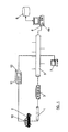
- Figure 1 schematically illustrates the system in accordance with a preferred embodiment of the invention.
- the system is coupled to a CAN bus 1 of a vehicle 2, and comprises a first hardware interface 3, connected to the bus 1 and to a computer network 5 (for example, an Ethernet network).
- a computer network 5 for example, an Ethernet network
- the first interface 3 comprises four functional modules (not illustrated in figure 1), namely:
- the system also comprises the second interface 4, also connected to the computer network 5 and which comprises four functional modules (not illustrated in figure 1), namely:
- a user may interact from his/her computer 7 or work station, for example from his/her personal computer, with elements of the vehicle 2 via the bus 1, via the computer network 5, via the first interface 3 and via second interface 4.
- the second interface includes a data server 4a configured to carry out the conversion from the first format into the second format.
- the computer 7 is configured to work as a client of the data server 4a, such that the computer 7 may request data from the data server 4a and obtain as an answer data in the second format from the server.
- the server 4a may be an OLE for Process Control (OPC) server, in which case, the second interface is configured to convert the format of the data, from the first format into the second format, by using the OLE for Process Control protocol.
- OPC OLE for Process Control
- the database includes the information and rules necessary for converting data from the first format (corresponding to the format in which the data travels through the bus 1) into the second format, which is the format that may be interpreted by the users and/or their computers.
- the database includes the information and rules to configure messages suitable for the control of the elements connected to the bus, once injected in the bus via the first interface. These messages are configured in accordance with instructions that the second interface 4 receives from the users, via the computer network 5, and following the rules and information contained in the database 6.
- a CANdb (CAN database) database from the Vector-Informatik firm, frequently used in the automotive field may be used as database.
- system comprises an additional system of acquisition of signals from elements of a vehicle, which comprises:
- the data and messages are sent as packets or frames with a format that may be like the one illustrated in figures 2A and 2B; namely, figure 2A reflects a frame in the CAN 2.0 A format, with an 11-bit identifier (201), and figure 2B, a frame in the CAN 2.0 B format, with a 29-bit identifier (201+211).
- the first interface 3 has a fixed configuration, that is, a configuration that never varies, it always carries out the same function. This first interface 3 constantly reads the data traveling through the CAN bus.
- the second interface 4 wants to receive the data circulating through the CAN bus, the second interface 4 makes a request to the first interface 3 for this data by means of a TCP-IP (Transmission Transfer Protocol/Internet Protocol) connection. From the moment when this connection between the first interface 3 and the second interface 4 is made, the first interface 3 sends all the messages circulating through the CAN bus to the second interface 4 via the computer network by means of a TCP-IP connection.
- TCP-IP Transmission Transfer Protocol/Internet Protocol
- the interaction between the first interface 3, the bus 1, and the computer network 5 is always carried out under a connection request from the second interface 4 to on the first interface 3, such that the first interface 3 is always waiting to receive a connection request from the second interface 4.
- the parameters to be configured of the first interface 3 are, on one hand, communication parameters of the computer network (for example, the IP direction within the computer network and the gateway direction allowing access to the network), and on the other hand, communication parameters of the CAN bus (for example, the data transfer rate through the CAN bus, generally 500 kbps).
- the second interface 4 has as an objective that the user first selects what information (CAN bus messages) he/she wants to visualize.
- the second interface 4 uses the information which is read from the database 6, where what data travels through the bus and how the data is structured within the CAN bus is reflected.
- the selection is made by means of two drop down menus containing which messages circulate through the CAN bus.
- the user selects the message he wants to display and accepts the selections by means of a push button.
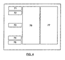
- Figure 4 schematically shows the user interface, that is, the display on the screen of the computer 7 of the user; this interface or screen shows the following elements:
- the screen of the computer 7 of the user will show two drop down menus for choosing the messages and signals that the user wants to display and the button for making the selection.
- the second interface 4 makes a TCP-IP connection on the first interface 3. At this moment, all the data traveling through the CAN bus is received by the second interface 4, which is in charge of displaying only the information selected by the user.
- the second interface 4 is programmed by using the LabVIEW® programming language, which allows the user to select and display the data traveling through the CAN bus.
- the interface 4 is provided with an OPC data server 4a such that it allows that other computers 7 connected to the computer network that have any application that functions as an OPC client, may also display the data that had been selected in the second interface 4. This option allows using commercial software applications for monitoring the data traveling through the CAN bus using the OPC protocol.
- the interface 4 also allows the user to create CAN messages according to the format defined in the database 6.
- the user introduces in the interface 4 the information he/she wants to send to the CAN bus in fields intended for the introduction of said information.
- the interface 4 generates a message that afterwards is sent periodically to the first interface 3 so as to be injected in the CAN bus. Thereby, it is possible to act on the different elements which are connected to the CAN bus.
- FIG. 5 schematically illustrates the operation of the second interface
- the hardware interface 3 is illustrated as a block diagram in figure 3. It is an electronic system mainly based on three main elements, a microcontroller 31 which carries out the specific function for which the first interface 3 has been designed (collect data from the CAN bus 1 and send it to the computer network 5 (Ethernet)), a specific integrated circuit called CAN 32 which acts as an interpreter of the data from the CAN bus, and finally, another specific integrated circuit called Ethernet controller 33 which acts as an interface for the communication via the computer network (Ethernet).
- a microcontroller 31 which carries out the specific function for which the first interface 3 has been designed (collect data from the CAN bus 1 and send it to the computer network 5 (Ethernet)
- CAN 32 which acts as an interpreter of the data from the CAN bus
- Ethernet controller 33 which acts as an interface for the communication via the computer network (Ethernet).
Landscapes
- Engineering & Computer Science (AREA)
- Signal Processing (AREA)
- Computer Networks & Wireless Communication (AREA)
- General Physics & Mathematics (AREA)
- Physics & Mathematics (AREA)
- Theoretical Computer Science (AREA)
- General Engineering & Computer Science (AREA)
- Health & Medical Sciences (AREA)
- Computing Systems (AREA)
- General Health & Medical Sciences (AREA)
- Medical Informatics (AREA)
- Small-Scale Networks (AREA)
- Train Traffic Observation, Control, And Security (AREA)
Abstract
Description
- The invention is encompassed within the field of data capture from a bus, especially in the automotive field, for the study of data related to vehicle systems and subsystems.
- Vehicles, for example automobiles, currently comprise increasingly complex systems necessary for the correct operation of the automobile. Systems, such as for example the electrical system, are constituted by devices and subsystems that can communicate among each other and/or with one or several control units via communication means that usually include as a data and message transmission path, a bus, frequently a CAN (Controller Area Network) bus.
- In order to analyze the operation of the different systems, subsystems and devices forming an automobile, it is typical to capture signals related to said subsystems and devices by means of sensors specifically provided to this end. It is also typical to capture the data and messages traveling through the bus (usually a CAN bus) as this data usually includes information related to the subsystems and devices interconnected with the bus.
- The CAN (Controller Area Network) bus is widely used in different industrial fields and in particular in the automotive world, and there is a variety of devices that allow analyzing the data and messages traveling through the bus. Most of these devices are cards with different formats (PCI, PCMCIA, PXI, etc.) that are inserted in a personal computer or rack, where the data analysis is carried out in the equipment itself.
- This way of carrying out the interaction between a personal computer and a bus (for example, a CAN bus through which data and messages that must be analyzed circulate) may work in a satisfactory manner in small installations, wherein the same personal computer is always used for data analysis. However, this way of carrying out the interaction is not satisfactory in situations in which carrying out the analysis of the data and interacting with the data from any of a plurality of computers is desired. For example, currently, the analysis of the behaviors of the subsystems and devices that are part of automobiles is a complex process in which a lot of times many different people take part. Thus, in accordance with the state of the art, so that each person may access the bus from his/her personal computer, it may be necessary to provide each personal computer with a card of the abovementioned type. However, this solution is not ideal, as it entails a high cost (related to obtaining and installing each card) and low flexibility (given that, for a person to access the bus from his/her personal computer, he/she first needs that the necessary card is installed for the access).
- Thus, it has been deemed desirable to develop a system that allows a person to access the data circulating through the bus from his/her personal computer without needing to have a special card installed in the computer.
- In accordance with the invention, this is achieved by making use of the fact that, in current work environments, normally the people in a work unit, department, workplace or company usually work with personal computers or the like connected to, for example, an Ethernet, LAN (Local Area Network) or Internet network.
- The invention relates to a system of monitoring and control of elements of a vehicle connected to a bus (for example, a CAN bus), characterized in that the system comprises:
- I) a first interface (for example, a preferably programmable hardware interface)
configured to be connected to the bus and to a computer network and which
comprises:
- means of capture of data circulating through the bus;
- means for transmitting said data to a second interface (preferably a software application that is executed in a computer) via a computer network (for example, an Ethernet, LAN or Internet network);
- means of reception of element control messages from said computer network; and
- means of insertion of said messages in the bus, such that said messages arrive at elements of the vehicle for the control of said elements; and
- II) said second interface, configured to be connected to said computer network
and which comprises:
- means of reception of data from the first interface;
- means of conversion of the format of said data, from a first format into a second format, in accordance with the conversion rules defined in a database accessible from said second interface;
- means of message configuration in accordance with instructions received via the computer network from at least one computer connected to said computer network, in accordance with configuration rules defined in said database accessible from said second interface; and
- means of sending said messages to the first interface for their insertion in the bus.
-
- Thereby, a user may interact from his/her computer or work station, for example from his/her personal computer, with elements of the vehicle connected to the bus via the computer network and via the first interface and second interface, both connected to the computer network. Thereby, the user does not need to use a computer provided with cards specific for communicating via a bus (for example, a CAN bus) of the vehicle, but the interaction is possible via any personal computer or work station by making use of the first interface and the second interface, which thereby and given that they are connected to the computer network, may be used by any user connected to the network. Thus, the invention allows, amongst other things, to simplify the task redistribution in a work team, as new technicians may take part in the process of analysis of a vehicle, by obtaining data from the bus of the vehicle and acting on elements connected to the bus of the vehicle, without needing to first obtain and install new specific cards in their computers and to connect said cards to the CAN bus. In the second interface, data of the first format (which may correspond to the format of the data as it travels through the bus) is converted into a second format suitable for the presentation of the relevant parameters to the user. Likewise, the second interface may receive instructions in a language used by the user and, starting from said instructions, in accordance with rules established in the database, configure messages that may be sent to the bus (via the first interface) with certain elements connected to the bus as destination and with a format that may be correctly interpreted by the elements.
- The second interface may include a data server configured to carry out the conversion from the first format into the second format, and the system may include at least one computer connected to the computer network and configured to work as a client of the data server, such that the computer may request data from the data server and obtain as an answer data in the second format from the server, that is, data corresponding to those traveling through the bus but in a format understandable for the user.
- Thereby, the entire infrastructure necessary for element monitoring and controlling via the bus (CAN bus) of the vehicle centers around both interfaces to which the users access from their computers via the computer network.
- The data server may be, for example, an OLE for Process Control (OPC: a communication standard) server. The second interface may be configured to convert the format of the data, from the first format into the second format, by using said OLE for Process Control (OPC) protocol.
- The database includes the information and rules necessary for converting data from the first format (which corresponds to the format in which the data travels through the bus) into the second format, which is the format that may be interpreted by the users and/or their computers. Likewise, the database includes the information and rules to configure messages suitable for the control of the elements connected to the bus, once injected in the bus via the first interface. These messages are configured in accordance with instructions that the second interface receives from the users, via the computer network, and following the rules and information contained in the database.
- Furthermore, the system may comprise an additional system of acquisition of signals from elements of a vehicle and which comprises:
- sensors configured to be directly connected to elements of the vehicle;
- means of acquisition of signals from said sensors; and
- at least a third interface between said means of acquisition of signals and the computer network, such that information on the signals from the sensors may be derived by computers connected to the computer network via said means of acquisition of signals.
- Thereby, more complete information on the vehicle may be obtained, receiving data not only from the elements connected to the bus, but also from other elements of the vehicle. For example, the sensors may be analog sensors for detecting vibrations, etc., in portions of the vehicle.
- Thereby, the user may interact with the elements connected to the bus and with other elements of the vehicle from any computer (for example, a personal computer) connected to the computer network, all via the computer network and without needing to install additional hardware in his/her computer.
- Next, a series of drawings, which aid in better understanding the invention and are expressly related to an embodiment of said invention which is presented as an illustrative and non-limiting example thereof, are described.
- Figure 1 is a schematic illustration of a system in accordance with a preferred embodiment of the invention.
- Figures 2A and 2B illustrate the format of the frames traveling through the CAN bus and which the first interface reads and interprets so as to send them to the second interface.
- Figure 3 is a schematic block diagram of the first hardware interface 3.
- Figure 4 shows a user interface as a screen configuration in the computer through which the user accesses the information.
- Figure 5 is a flow chart schematically showing the operation of a software interface in accordance with a preferred embodiment of the invention.
-
- Figure 1 schematically illustrates the system in accordance with a preferred embodiment of the invention. The system is coupled to a CAN bus 1 of a vehicle 2, and comprises a first hardware interface 3, connected to the bus 1 and to a computer network 5 (for example, an Ethernet network).
- The first interface 3 comprises four functional modules (not illustrated in figure 1), namely:
- means of capture of data circulating through the bus;
- means for transmitting said data to a second interface 4 (which is constituted
by a software application that is executed in a computer) via the
computer network 5; - means of reception of element control messages from said
computer network 5; - and means of insertion of said messages in the bus 1, such that said messages arrive at elements of the vehicle for the control of said elements.
- On the other hand, the system also comprises the second interface 4, also connected to the
computer network 5 and which comprises four functional modules (not illustrated in figure 1), namely: - means of reception of data from the first interface 3;
- means of conversion of the format of said data from a first format into a
second format, in accordance with the conversion rules defined in a
database 6 accessible from said second interface 4; - means of message configuration in accordance with instructions received via
the
computer network 5 from at least onecomputer 7 connected to said computer network, in accordance with configuration rules defined in said database accessible 6 from said second interface 4; and - means of sending said messages to the first interface 3.
- Thereby, a user may interact from his/her
computer 7 or work station, for example from his/her personal computer, with elements of the vehicle 2 via the bus 1, via thecomputer network 5, via the first interface 3 and via second interface 4. - The second interface includes a
data server 4a configured to carry out the conversion from the first format into the second format. Thecomputer 7 is configured to work as a client of thedata server 4a, such that thecomputer 7 may request data from thedata server 4a and obtain as an answer data in the second format from the server. Theserver 4a may be an OLE for Process Control (OPC) server, in which case, the second interface is configured to convert the format of the data, from the first format into the second format, by using the OLE for Process Control protocol. - The database includes the information and rules necessary for converting data from the first format (corresponding to the format in which the data travels through the bus 1) into the second format, which is the format that may be interpreted by the users and/or their computers. Likewise, the database includes the information and rules to configure messages suitable for the control of the elements connected to the bus, once injected in the bus via the first interface. These messages are configured in accordance with instructions that the second interface 4 receives from the users, via the
computer network 5, and following the rules and information contained in thedatabase 6. For example, a CANdb (CAN database) database from the Vector-Informatik firm, frequently used in the automotive field, may be used as database. - Furthermore, the system comprises an additional system of acquisition of signals from elements of a vehicle, which comprises:
-
sensors 10 configured to be directly connected to elements of the vehicle; - means of acquisition of signals 11 (for example, analog signals) from said sensors; and
- at least a
third interface 12 between said means of acquisition of signals and the computer network, such that information on the signals from the sensors may be obtained by computers connected to the computer network via said means of acquisition of signals. - Now, the configuration and function of the relevant elements of the invention will be discussed in more detail.
- In the CAN bus, the data and messages are sent as packets or frames with a format that may be like the one illustrated in figures 2A and 2B; namely, figure 2A reflects a frame in the CAN 2.0 A format, with an 11-bit identifier (201), and figure 2B, a frame in the CAN 2.0 B format, with a 29-bit identifier (201+211).
- The format of the frames is well known by any person of ordinary skill in the art, whereby it is not necessary to describe it here; basically, as known, the frames comprise the following elements:
- 200: "START" (1 bit)
- 201: "Identifier" (11 bits): the "identifier" indicating what information is contained in the frame, that is, the type of message that it is.
- 202: "RTR" (1 bit)
- 203: "IDE" (1 bit)
- 204: "r0" (1 bit)
- 205: "DLC" (4 bits)
- 206: "Data" (nx8 bits, where 0≤n≤8): the data field containing the information useful for the user.
- 207: "CRC" ("Cyclic Redundancy Check") (15 bits): a control number calculated from the original contents of the rest of the frame and intended to allow the detection and correction of errors that occur in the transmission.
- 208: "ACK" (2 bits)
- 209: "EOF+IFS" (10 bits)
- 210: "SRR" (1 bit): (only in the CAN 2.0 B format)
- 211: "Identifier" (18 bits) (only in the CAN 2.0 B format): an additional identifier field allowing to increase the information on the type of message.
- 212 "r1" (1 bit): (only in the CAN 2.0 B format)
-
- The first interface 3 has a fixed configuration, that is, a configuration that never varies, it always carries out the same function. This first interface 3 constantly reads the data traveling through the CAN bus. When the second interface 4 wants to receive the data circulating through the CAN bus, the second interface 4 makes a request to the first interface 3 for this data by means of a TCP-IP (Transmission Transfer Protocol/Internet Protocol) connection. From the moment when this connection between the first interface 3 and the second interface 4 is made, the first interface 3 sends all the messages circulating through the CAN bus to the second interface 4 via the computer network by means of a TCP-IP connection. The interaction between the first interface 3, the bus 1, and the
computer network 5 is always carried out under a connection request from the second interface 4 to on the first interface 3, such that the first interface 3 is always waiting to receive a connection request from the second interface 4. The parameters to be configured of the first interface 3 are, on one hand, communication parameters of the computer network (for example, the IP direction within the computer network and the gateway direction allowing access to the network), and on the other hand, communication parameters of the CAN bus (for example, the data transfer rate through the CAN bus, generally 500 kbps). - On the other hand, the second interface 4 has as an objective that the user first selects what information (CAN bus messages) he/she wants to visualize. In order to carry out this selection, the second interface 4 uses the information which is read from the
database 6, where what data travels through the bus and how the data is structured within the CAN bus is reflected. The selection is made by means of two drop down menus containing which messages circulate through the CAN bus. The user selects the message he wants to display and accepts the selections by means of a push button. Figure 4 schematically shows the user interface, that is, the display on the screen of thecomputer 7 of the user; this interface or screen shows the following elements: - 71: menu of selection of the messages circulating through the CAN bus
- 72: menu of selection of the signals circulating through the CAN bus
- 73: buttons for making the selection of the information to be displayed
- 74: configuration of the IP direction of the hardware interface
- 75: configuration of the
database 6 - 76: displays for displaying the selected signals
- 77: controls for generating the CAN messages which will be sent to the first interface 3.
-
- That is, the screen of the
computer 7 of the user will show two drop down menus for choosing the messages and signals that the user wants to display and the button for making the selection. Once the selection is made, the second interface 4 makes a TCP-IP connection on the first interface 3. At this moment, all the data traveling through the CAN bus is received by the second interface 4, which is in charge of displaying only the information selected by the user. - In accordance with a preferred embodiment, the second interface 4 is programmed by using the LabVIEW® programming language, which allows the user to select and display the data traveling through the CAN bus. The interface 4 is provided with an
OPC data server 4a such that it allows thatother computers 7 connected to the computer network that have any application that functions as an OPC client, may also display the data that had been selected in the second interface 4. This option allows using commercial software applications for monitoring the data traveling through the CAN bus using the OPC protocol. - The interface 4 also allows the user to create CAN messages according to the format defined in the
database 6. The user introduces in the interface 4 the information he/she wants to send to the CAN bus in fields intended for the introduction of said information. In accordance with the rules specified in thedatabase 6, the interface 4 generates a message that afterwards is sent periodically to the first interface 3 so as to be injected in the CAN bus. Thereby, it is possible to act on the different elements which are connected to the CAN bus. - Figure 5 schematically illustrates the operation of the second interface:
- 40: the user configures the location of the file of the database 6 (CANdb) (a file with a DBC extension)
- 41: the user configures the IP direction of the first interface (hardware interface) in order to be able to establish the communication between the first interface and the software interface (software interface)
- 42: the software interface reads from the database the messages and signals available in the CAN bus
- 43: the software interface displays on screen (that is, on the screen of the
computer 7 of the user), by means of drop down menus, the available messages and signals to the user - 44: the user selects, by means of the drop down menus, what information (signals) from the CAN bus he/she wants to monitor
- 45: the user configures which messages are to be exported from the second interface to any OPC client by using the OPC protocol
- 46: the second interface makes a connection to the first interface in order to
collect via the network 5 (Ethernet) the data (messages) from the CAN bus that the first
interface reads and sends to the second interface via the
network 5 - 47: the second interface displays on screen (in the
computer 7 of the user) the information selected by the user. -
- The hardware interface 3 is illustrated as a block diagram in figure 3. It is an electronic system mainly based on three main elements, a
microcontroller 31 which carries out the specific function for which the first interface 3 has been designed (collect data from the CAN bus 1 and send it to the computer network 5 (Ethernet)), a specific integrated circuit calledCAN 32 which acts as an interpreter of the data from the CAN bus, and finally, another specific integrated circuit calledEthernet controller 33 which acts as an interface for the communication via the computer network (Ethernet). - Throughout the present description and claims, the word "comprises" and variations thereof, such as "comprising", are not intended to exclude other steps or components.
Claims (9)
- A system of monitoring and control of elements of a vehicle (2) connected to a bus (1), characterized in that the system comprises:I) a first interface (3) configured to be connected to the bus (1) and to a computer network (5) and which comprises:means of capture of data circulating through the bus (1);means for transmitting said data to a second interface (4) via the computer network (5);means of reception of element control messages from said computer network (5);and means of insertion of said messages in the bus (1), such that said messages arrive at elements of the vehicle for the control of said elements; andII) said second interface (4), configured to be connected to said computer network (5) and which comprises:means of reception of data from the first interface (3);means of conversion of the format of said data, from a first format into a second format, in accordance with the conversion rules defined in a database (6) accessible from said second interface (4);means of message configuration in accordance with instructions received via the computer network from at least one computer (7) connected to said computer network, in accordance with configuration rules defined in said database (6) accessible from said second interface; andmeans of sending said messages to the first interface (3).
- A system according to claim 1, characterized in that the second interface (4) includes a data server (4a) configured to carry out the conversion from the first format into the second format, and in that the system includes at least one computer (7) connected to the computer network (5) and configured to work as a client of the data server (4a), such that the computer may request data from the data server and obtain as an answer data in the second format from the server.
- A system according to claim 2, characterized in that the data server (4a) is an OLE for Process Control server.
- A system according to any of the preceding claims, characterized in that the second interface (4) is configured to convert the format of the data, from the first format into the second format, by using the OLE for Process Control protocol.
- A system according to any of the preceding claims, characterized in that the bus (1) is a CAN bus.
- A system according to any of the preceding claims, characterized in that the computer network (5) is an Ethernet network.
- A system according to any of the preceding claims, characterized in that the first interface (3) is a hardware interface.
- A system according to any of the preceding claims, characterized in that the second interface (4) is a software application which is executed in a computer.
- A system according to any of the preceding claims, characterized in that it comprises
an additional system of acquisition of signals from elements of a vehicle and which comprises:sensors (10) configured to be directly connected to elements of the vehicle;means of acquisition of signals (11) from said sensors; yat least a third interface (12) between said means of acquisition of signals and the computer network, such that information on the signals from the sensors may be obtained by computers connected to the computer network via said means of acquisition of signals.
Applications Claiming Priority (2)
| Application Number | Priority Date | Filing Date | Title |
|---|---|---|---|
| ES200400542P | 2004-03-05 | ||
| ES200400542A ES2239537B1 (en) | 2004-03-05 | 2004-03-05 | SYSTEM OF MONITORING AND CONTROL OF ELEMENTS OF A VEHICLE. |
Publications (2)
| Publication Number | Publication Date |
|---|---|
| EP1571788A1 true EP1571788A1 (en) | 2005-09-07 |
| EP1571788B1 EP1571788B1 (en) | 2006-12-27 |
Family
ID=35004488
Family Applications (1)
| Application Number | Title | Priority Date | Filing Date |
|---|---|---|---|
| EP04380292A Expired - Lifetime EP1571788B1 (en) | 2004-03-05 | 2004-12-30 | System of monitoring and control of elements of a vehicle |
Country Status (4)
| Country | Link |
|---|---|
| EP (1) | EP1571788B1 (en) |
| AT (1) | ATE349835T1 (en) |
| DE (1) | DE602004003899T2 (en) |
| ES (2) | ES2239537B1 (en) |
Cited By (11)
| Publication number | Priority date | Publication date | Assignee | Title |
|---|---|---|---|---|
| CN101196884B (en) * | 2006-12-07 | 2010-05-12 | 厦门雅迅网络股份有限公司 | A data query processing method for a vehicle database |
| JP2015154481A (en) * | 2014-02-13 | 2015-08-24 | 現代自動車株式会社Hyundaimotor Company | Processor for performing signal conversion between Ethernet and CAN communication in vehicle and signal conversion method |
| US12034601B2 (en) | 2019-09-20 | 2024-07-09 | Sonatus, Inc. | System, method, and apparatus to support mixed network communications on a vehicle |
| US12073665B2 (en) | 2019-09-20 | 2024-08-27 | Sonatus, Inc. | System, method, and apparatus for managing vehicle data collection |
| US12094259B2 (en) | 2020-03-06 | 2024-09-17 | Sonatus, Inc. | System, method, and apparatus for managing vehicle automation |
| US12103479B2 (en) | 2020-03-06 | 2024-10-01 | Sonatus, Inc. | System, method, and apparatus for managing vehicle automation |
| US12119996B2 (en) | 2019-09-20 | 2024-10-15 | Sonatus, Inc. | System, method, and apparatus to execute vehicle communications using a zonal architecture |
| US12211323B2 (en) | 2020-03-06 | 2025-01-28 | Sonatus, Inc. | System, method, and apparatus for managing vehicle automation |
| US12403921B2 (en) | 2020-03-06 | 2025-09-02 | Sonatus, Inc. | System, method, and apparatus for managing vehicle automation |
| US12415479B2 (en) | 2020-03-06 | 2025-09-16 | Sonatus, Inc. | System, method, and apparatus for managing vehicle data collection |
| US12573245B2 (en) | 2020-03-06 | 2026-03-10 | Sonatus, Inc. | System, method, and apparatus for managing vehicle automation |
Families Citing this family (1)
| Publication number | Priority date | Publication date | Assignee | Title |
|---|---|---|---|---|
| ES2958114B2 (en) * | 2022-07-04 | 2024-06-11 | Seat Sa | TEST BANK AND TESTING PROCEDURE OF THE INFORMATION ISSUED TO THE USER OF A VEHICLE |
Citations (3)
| Publication number | Priority date | Publication date | Assignee | Title |
|---|---|---|---|---|
| WO2000060842A1 (en) * | 1999-04-01 | 2000-10-12 | Siemens Aktiengesellschaft | System and method for especially graphically monitoring and/or remote controlling stationary and/or mobile devices |
| US20020034180A1 (en) * | 1999-02-26 | 2002-03-21 | Siemens Ag | Method for transmitting ethernet frames |
| US6654355B1 (en) * | 1999-12-14 | 2003-11-25 | Schneider Automation Inc. | Bridge for CAN to TCP/IP connection |
Family Cites Families (4)
| Publication number | Priority date | Publication date | Assignee | Title |
|---|---|---|---|---|
| DE4036241A1 (en) * | 1990-11-14 | 1992-05-21 | Joerg Golombek | Measuring and evaluating physical data of vehicle model - using microprocessor with program and data memory, connected via A=D converters to sensors of different parameters |
| US5732074A (en) * | 1996-01-16 | 1998-03-24 | Cellport Labs, Inc. | Mobile portable wireless communication system |
| NZ524546A (en) * | 2000-08-18 | 2004-11-26 | Nnt Inc | System, method and computer program product for remote vehicle diagnostics, monitoring, configuring and reprogramming |
| AT411973B (en) * | 2001-01-26 | 2004-08-26 | Fronius Schweissmasch Prod | METHOD FOR OPERATING A WELDING DEVICE OR A WELDING SYSTEM |
-
2004
- 2004-03-05 ES ES200400542A patent/ES2239537B1/en not_active Expired - Fee Related
- 2004-12-30 AT AT04380292T patent/ATE349835T1/en not_active IP Right Cessation
- 2004-12-30 ES ES04380292T patent/ES2280925T3/en not_active Expired - Lifetime
- 2004-12-30 DE DE602004003899T patent/DE602004003899T2/en not_active Expired - Lifetime
- 2004-12-30 EP EP04380292A patent/EP1571788B1/en not_active Expired - Lifetime
Patent Citations (3)
| Publication number | Priority date | Publication date | Assignee | Title |
|---|---|---|---|---|
| US20020034180A1 (en) * | 1999-02-26 | 2002-03-21 | Siemens Ag | Method for transmitting ethernet frames |
| WO2000060842A1 (en) * | 1999-04-01 | 2000-10-12 | Siemens Aktiengesellschaft | System and method for especially graphically monitoring and/or remote controlling stationary and/or mobile devices |
| US6654355B1 (en) * | 1999-12-14 | 2003-11-25 | Schneider Automation Inc. | Bridge for CAN to TCP/IP connection |
Cited By (24)
| Publication number | Priority date | Publication date | Assignee | Title |
|---|---|---|---|---|
| CN101196884B (en) * | 2006-12-07 | 2010-05-12 | 厦门雅迅网络股份有限公司 | A data query processing method for a vehicle database |
| JP2015154481A (en) * | 2014-02-13 | 2015-08-24 | 現代自動車株式会社Hyundaimotor Company | Processor for performing signal conversion between Ethernet and CAN communication in vehicle and signal conversion method |
| US12177081B2 (en) | 2019-09-20 | 2024-12-24 | Sonatus, Inc. | System, method, and apparatus to execute vehicle communications using a zonal architecture |
| US12199824B2 (en) | 2019-09-20 | 2025-01-14 | Sonatus, Inc. | System, method, and apparatus to execute vehicle communications using a zonal architecture |
| US12395406B2 (en) | 2019-09-20 | 2025-08-19 | Sonatus, Inc. | System, method, and apparatus to execute vehicle communications using a zonal architecture |
| US12261747B2 (en) | 2019-09-20 | 2025-03-25 | Sonatus, Inc. | System, method, and apparatus to execute vehicle communications using a zonal architecture |
| US12118830B2 (en) | 2019-09-20 | 2024-10-15 | Sonatus, Inc. | System, method, and apparatus for managing vehicle data collection |
| US12119996B2 (en) | 2019-09-20 | 2024-10-15 | Sonatus, Inc. | System, method, and apparatus to execute vehicle communications using a zonal architecture |
| US12142091B2 (en) | 2019-09-20 | 2024-11-12 | Sonatus, Inc. | System, method, and apparatus for managing vehicle data collection |
| US12159492B2 (en) | 2019-09-20 | 2024-12-03 | Sonatus, Inc. | System, method, and apparatus for managing vehicle data collection |
| US12177079B2 (en) | 2019-09-20 | 2024-12-24 | Sonatus, Inc. | System, method, and apparatus to execute vehicle communications using a zonal architecture |
| US12244464B2 (en) | 2019-09-20 | 2025-03-04 | Sonatus, Inc. | System, method, and apparatus for extra vehicle communications control |
| US12073665B2 (en) | 2019-09-20 | 2024-08-27 | Sonatus, Inc. | System, method, and apparatus for managing vehicle data collection |
| US12034601B2 (en) | 2019-09-20 | 2024-07-09 | Sonatus, Inc. | System, method, and apparatus to support mixed network communications on a vehicle |
| US12177080B2 (en) | 2019-09-20 | 2024-12-24 | Sonatus, Inc. | System, method, and apparatus to execute vehicle communications using a zonal architecture |
| US12211324B2 (en) | 2019-09-20 | 2025-01-28 | Sonatus, Inc. | System, method, and apparatus for managing vehicle data collection |
| US12230071B2 (en) | 2019-09-20 | 2025-02-18 | Sonatus, Inc. | System, method, and apparatus for managing vehicle data collection |
| US12211323B2 (en) | 2020-03-06 | 2025-01-28 | Sonatus, Inc. | System, method, and apparatus for managing vehicle automation |
| US12103479B2 (en) | 2020-03-06 | 2024-10-01 | Sonatus, Inc. | System, method, and apparatus for managing vehicle automation |
| US12094259B2 (en) | 2020-03-06 | 2024-09-17 | Sonatus, Inc. | System, method, and apparatus for managing vehicle automation |
| US12403921B2 (en) | 2020-03-06 | 2025-09-02 | Sonatus, Inc. | System, method, and apparatus for managing vehicle automation |
| US12415479B2 (en) | 2020-03-06 | 2025-09-16 | Sonatus, Inc. | System, method, and apparatus for managing vehicle data collection |
| US12528442B2 (en) | 2020-03-06 | 2026-01-20 | Sonatus, Inc. | System, method, and apparatus for managing vehicle data collection |
| US12573245B2 (en) | 2020-03-06 | 2026-03-10 | Sonatus, Inc. | System, method, and apparatus for managing vehicle automation |
Also Published As
| Publication number | Publication date |
|---|---|
| EP1571788B1 (en) | 2006-12-27 |
| ES2239537A1 (en) | 2005-09-16 |
| DE602004003899T2 (en) | 2007-08-30 |
| DE602004003899D1 (en) | 2007-02-08 |
| ES2280925T3 (en) | 2007-09-16 |
| ATE349835T1 (en) | 2007-01-15 |
| ES2239537B1 (en) | 2006-11-16 |
Similar Documents
| Publication | Publication Date | Title |
|---|---|---|
| EP1571788B1 (en) | System of monitoring and control of elements of a vehicle | |
| EP0875111B1 (en) | Mobile portable wireless communication system | |
| US6956461B2 (en) | Apparatus and method for remotely controlling household appliances | |
| US9305408B2 (en) | Multiple electronic control unit diagnosing system and method for vehicle | |
| US7693987B2 (en) | System using BACnet visual test shell for monitoring and analyzing data frames on BACnet MS/TP communication network | |
| US20030171111A1 (en) | Cellular telephone interface apparatus and methods | |
| US20200382597A1 (en) | Vehicle diagnostic communication apparatus, system including the same and method thereof | |
| US20020156926A1 (en) | Industrial control system with autonomous web server | |
| CN101741637B (en) | Method and device for diagnosing networks, in particular fieldbus systems | |
| KR102122376B1 (en) | Connected gateway for vehicle | |
| EP3078165B1 (en) | Web-based interaction with building automation | |
| WO1999039505A1 (en) | Networked security system for network-based monitoring and control of an environment | |
| CN117130318B (en) | Industrial data collection methods, devices, systems and readable storage media | |
| CN101790109A (en) | Control device, communication device for control, relay device, control system, and control method | |
| CN101300534A (en) | Method and system for transmitting periodic and aperiodic data | |
| EP1870850A1 (en) | Connection adapter for communication device | |
| CN103838227A (en) | Vehicle body data processing device and vehicle body data processing method thereof | |
| KR20090066766A (en) | Integrated remote monitoring system of uninterruptible power supply | |
| CN114172971A (en) | Gateway application system and method compatible with multiple different protocol sub-devices | |
| EP2790356A1 (en) | Network analysis device, management system, network analysis method and program | |
| CN215835419U (en) | Adaptive circuit and device based on OBD communication protocol | |
| JP7360888B2 (en) | Anomaly detection device, security system and anomaly detection method | |
| EP1722537A1 (en) | Method for processing messages, data processing device and computer program product | |
| CN106357772A (en) | Vehicle-mounted wireless communication system and method | |
| EP4203418B1 (en) | Method for analyzing services of nodes of a network |
Legal Events
| Date | Code | Title | Description |
|---|---|---|---|
| PUAI | Public reference made under article 153(3) epc to a published international application that has entered the european phase |
Free format text: ORIGINAL CODE: 0009012 |
|
| AK | Designated contracting states |
Kind code of ref document: A1 Designated state(s): AT BE BG CH CY CZ DE DK EE ES FI FR GB GR HU IE IS IT LI LT LU MC NL PL PT RO SE SI SK TR |
|
| AX | Request for extension of the european patent |
Extension state: AL BA HR LV MK YU |
|
| RIN1 | Information on inventor provided before grant (corrected) |
Inventor name: JIMENEZ BARGALLO, JOSE ANTONIO Inventor name: MANUEL LAZARO, ANTONIO Inventor name: DEL RIO FERNANDEZ, JOAQUIN |
|
| RIN1 | Information on inventor provided before grant (corrected) |
Inventor name: MANUEL LAZARO, ANTONIO Inventor name: JIMENEZ BARGALLO, JOSE ANTONIO Inventor name: DEL RIO FERNANDEZ, JOAQUIN CTVG |
|
| 17P | Request for examination filed |
Effective date: 20060203 |
|
| AKX | Designation fees paid |
Designated state(s): AT BE BG CH CY CZ DE DK EE ES FI FR GB GR HU IE IS IT LI LT LU MC NL PL PT RO SE SI SK TR |
|
| R17C | First examination report despatched (corrected) |
Effective date: 20060302 |
|
| GRAP | Despatch of communication of intention to grant a patent |
Free format text: ORIGINAL CODE: EPIDOSNIGR1 |
|
| GRAS | Grant fee paid |
Free format text: ORIGINAL CODE: EPIDOSNIGR3 |
|
| GRAA | (expected) grant |
Free format text: ORIGINAL CODE: 0009210 |
|
| AK | Designated contracting states |
Kind code of ref document: B1 Designated state(s): AT BE BG CH CY CZ DE DK EE ES FI FR GB GR HU IE IS IT LI LT LU MC NL PL PT RO SE SI SK TR |
|
| PG25 | Lapsed in a contracting state [announced via postgrant information from national office to epo] |
Ref country code: PL Free format text: LAPSE BECAUSE OF FAILURE TO SUBMIT A TRANSLATION OF THE DESCRIPTION OR TO PAY THE FEE WITHIN THE PRESCRIBED TIME-LIMIT Effective date: 20061227 Ref country code: LT Free format text: LAPSE BECAUSE OF FAILURE TO SUBMIT A TRANSLATION OF THE DESCRIPTION OR TO PAY THE FEE WITHIN THE PRESCRIBED TIME-LIMIT Effective date: 20061227 Ref country code: AT Free format text: LAPSE BECAUSE OF FAILURE TO SUBMIT A TRANSLATION OF THE DESCRIPTION OR TO PAY THE FEE WITHIN THE PRESCRIBED TIME-LIMIT Effective date: 20061227 Ref country code: CH Free format text: LAPSE BECAUSE OF FAILURE TO SUBMIT A TRANSLATION OF THE DESCRIPTION OR TO PAY THE FEE WITHIN THE PRESCRIBED TIME-LIMIT Effective date: 20061227 Ref country code: FI Free format text: LAPSE BECAUSE OF FAILURE TO SUBMIT A TRANSLATION OF THE DESCRIPTION OR TO PAY THE FEE WITHIN THE PRESCRIBED TIME-LIMIT Effective date: 20061227 Ref country code: BE Free format text: LAPSE BECAUSE OF FAILURE TO SUBMIT A TRANSLATION OF THE DESCRIPTION OR TO PAY THE FEE WITHIN THE PRESCRIBED TIME-LIMIT Effective date: 20061227 Ref country code: NL Free format text: LAPSE BECAUSE OF FAILURE TO SUBMIT A TRANSLATION OF THE DESCRIPTION OR TO PAY THE FEE WITHIN THE PRESCRIBED TIME-LIMIT Effective date: 20061227 Ref country code: CZ Free format text: LAPSE BECAUSE OF FAILURE TO SUBMIT A TRANSLATION OF THE DESCRIPTION OR TO PAY THE FEE WITHIN THE PRESCRIBED TIME-LIMIT Effective date: 20061227 Ref country code: SI Free format text: LAPSE BECAUSE OF FAILURE TO SUBMIT A TRANSLATION OF THE DESCRIPTION OR TO PAY THE FEE WITHIN THE PRESCRIBED TIME-LIMIT Effective date: 20061227 Ref country code: DK Free format text: LAPSE BECAUSE OF FAILURE TO SUBMIT A TRANSLATION OF THE DESCRIPTION OR TO PAY THE FEE WITHIN THE PRESCRIBED TIME-LIMIT Effective date: 20061227 Ref country code: RO Free format text: LAPSE BECAUSE OF FAILURE TO SUBMIT A TRANSLATION OF THE DESCRIPTION OR TO PAY THE FEE WITHIN THE PRESCRIBED TIME-LIMIT Effective date: 20061227 Ref country code: SK Free format text: LAPSE BECAUSE OF FAILURE TO SUBMIT A TRANSLATION OF THE DESCRIPTION OR TO PAY THE FEE WITHIN THE PRESCRIBED TIME-LIMIT Effective date: 20061227 Ref country code: LI Free format text: LAPSE BECAUSE OF FAILURE TO SUBMIT A TRANSLATION OF THE DESCRIPTION OR TO PAY THE FEE WITHIN THE PRESCRIBED TIME-LIMIT Effective date: 20061227 |
|
| REG | Reference to a national code |
Ref country code: GB Ref legal event code: FG4D |
|
| PG25 | Lapsed in a contracting state [announced via postgrant information from national office to epo] |
Ref country code: MC Free format text: LAPSE BECAUSE OF NON-PAYMENT OF DUE FEES Effective date: 20061231 |
|
| PG25 | Lapsed in a contracting state [announced via postgrant information from national office to epo] |
Ref country code: IE Free format text: LAPSE BECAUSE OF NON-PAYMENT OF DUE FEES Effective date: 20070102 |
|
| REG | Reference to a national code |
Ref country code: IE Ref legal event code: FG4D |
|
| REF | Corresponds to: |
Ref document number: 602004003899 Country of ref document: DE Date of ref document: 20070208 Kind code of ref document: P |
|
| PG25 | Lapsed in a contracting state [announced via postgrant information from national office to epo] |
Ref country code: BG Free format text: LAPSE BECAUSE OF FAILURE TO SUBMIT A TRANSLATION OF THE DESCRIPTION OR TO PAY THE FEE WITHIN THE PRESCRIBED TIME-LIMIT Effective date: 20070327 Ref country code: SE Free format text: LAPSE BECAUSE OF FAILURE TO SUBMIT A TRANSLATION OF THE DESCRIPTION OR TO PAY THE FEE WITHIN THE PRESCRIBED TIME-LIMIT Effective date: 20070327 |
|
| PG25 | Lapsed in a contracting state [announced via postgrant information from national office to epo] |
Ref country code: IS Free format text: LAPSE BECAUSE OF FAILURE TO SUBMIT A TRANSLATION OF THE DESCRIPTION OR TO PAY THE FEE WITHIN THE PRESCRIBED TIME-LIMIT Effective date: 20070427 |
|
| PG25 | Lapsed in a contracting state [announced via postgrant information from national office to epo] |
Ref country code: PT Free format text: LAPSE BECAUSE OF FAILURE TO SUBMIT A TRANSLATION OF THE DESCRIPTION OR TO PAY THE FEE WITHIN THE PRESCRIBED TIME-LIMIT Effective date: 20070528 |
|
| ET | Fr: translation filed | ||
| NLV1 | Nl: lapsed or annulled due to failure to fulfill the requirements of art. 29p and 29m of the patents act | ||
| REG | Reference to a national code |
Ref country code: CH Ref legal event code: PL |
|
| REG | Reference to a national code |
Ref country code: ES Ref legal event code: FG2A Ref document number: 2280925 Country of ref document: ES Kind code of ref document: T3 |
|
| PLBE | No opposition filed within time limit |
Free format text: ORIGINAL CODE: 0009261 |
|
| STAA | Information on the status of an ep patent application or granted ep patent |
Free format text: STATUS: NO OPPOSITION FILED WITHIN TIME LIMIT |
|
| REG | Reference to a national code |
Ref country code: FR Ref legal event code: ST Effective date: 20071030 |
|
| 26N | No opposition filed |
Effective date: 20070928 |
|
| REG | Reference to a national code |
Ref country code: FR Ref legal event code: FC |
|
| PG25 | Lapsed in a contracting state [announced via postgrant information from national office to epo] |
Ref country code: FR Free format text: LAPSE BECAUSE OF NON-PAYMENT OF DUE FEES Effective date: 20070102 Ref country code: GR Free format text: LAPSE BECAUSE OF FAILURE TO SUBMIT A TRANSLATION OF THE DESCRIPTION OR TO PAY THE FEE WITHIN THE PRESCRIBED TIME-LIMIT Effective date: 20070328 |
|
| PG25 | Lapsed in a contracting state [announced via postgrant information from national office to epo] |
Ref country code: EE Free format text: LAPSE BECAUSE OF FAILURE TO SUBMIT A TRANSLATION OF THE DESCRIPTION OR TO PAY THE FEE WITHIN THE PRESCRIBED TIME-LIMIT Effective date: 20061227 |
|
| PG25 | Lapsed in a contracting state [announced via postgrant information from national office to epo] |
Ref country code: HU Free format text: LAPSE BECAUSE OF FAILURE TO SUBMIT A TRANSLATION OF THE DESCRIPTION OR TO PAY THE FEE WITHIN THE PRESCRIBED TIME-LIMIT Effective date: 20070628 Ref country code: LU Free format text: LAPSE BECAUSE OF NON-PAYMENT OF DUE FEES Effective date: 20061230 Ref country code: TR Free format text: LAPSE BECAUSE OF FAILURE TO SUBMIT A TRANSLATION OF THE DESCRIPTION OR TO PAY THE FEE WITHIN THE PRESCRIBED TIME-LIMIT Effective date: 20061227 |
|
| PGRI | Patent reinstated in contracting state [announced from national office to epo] |
Ref country code: FR Effective date: 20080116 |
|
| PG25 | Lapsed in a contracting state [announced via postgrant information from national office to epo] |
Ref country code: CY Free format text: LAPSE BECAUSE OF FAILURE TO SUBMIT A TRANSLATION OF THE DESCRIPTION OR TO PAY THE FEE WITHIN THE PRESCRIBED TIME-LIMIT Effective date: 20061227 |
|
| REG | Reference to a national code |
Ref country code: FR Ref legal event code: PLFP Year of fee payment: 12 |
|
| REG | Reference to a national code |
Ref country code: FR Ref legal event code: PLFP Year of fee payment: 13 |
|
| REG | Reference to a national code |
Ref country code: FR Ref legal event code: PLFP Year of fee payment: 14 |
|
| PGFP | Annual fee paid to national office [announced via postgrant information from national office to epo] |
Ref country code: FR Payment date: 20191230 Year of fee payment: 16 |
|
| PGFP | Annual fee paid to national office [announced via postgrant information from national office to epo] |
Ref country code: ES Payment date: 20200123 Year of fee payment: 16 Ref country code: IT Payment date: 20191220 Year of fee payment: 16 Ref country code: GB Payment date: 20191226 Year of fee payment: 16 Ref country code: DE Payment date: 20200227 Year of fee payment: 16 |
|
| REG | Reference to a national code |
Ref country code: DE Ref legal event code: R119 Ref document number: 602004003899 Country of ref document: DE |
|
| GBPC | Gb: european patent ceased through non-payment of renewal fee |
Effective date: 20201230 |
|
| PG25 | Lapsed in a contracting state [announced via postgrant information from national office to epo] |
Ref country code: IT Free format text: LAPSE BECAUSE OF NON-PAYMENT OF DUE FEES Effective date: 20201230 Ref country code: FR Free format text: LAPSE BECAUSE OF NON-PAYMENT OF DUE FEES Effective date: 20201231 |
|
| PG25 | Lapsed in a contracting state [announced via postgrant information from national office to epo] |
Ref country code: GB Free format text: LAPSE BECAUSE OF NON-PAYMENT OF DUE FEES Effective date: 20201230 Ref country code: DE Free format text: LAPSE BECAUSE OF NON-PAYMENT OF DUE FEES Effective date: 20210701 |
|
| REG | Reference to a national code |
Ref country code: ES Ref legal event code: FD2A Effective date: 20220412 |
|
| PG25 | Lapsed in a contracting state [announced via postgrant information from national office to epo] |
Ref country code: ES Free format text: LAPSE BECAUSE OF NON-PAYMENT OF DUE FEES Effective date: 20201231 |