EP1571554A2 - Redundant memory architecture with defragmentation capability - Google Patents
Redundant memory architecture with defragmentation capability Download PDFInfo
- Publication number
- EP1571554A2 EP1571554A2 EP05300048A EP05300048A EP1571554A2 EP 1571554 A2 EP1571554 A2 EP 1571554A2 EP 05300048 A EP05300048 A EP 05300048A EP 05300048 A EP05300048 A EP 05300048A EP 1571554 A2 EP1571554 A2 EP 1571554A2
- Authority
- EP
- European Patent Office
- Prior art keywords
- memory
- inactive
- active
- architecture
- contents
- Prior art date
- Legal status (The legal status is an assumption and is not a legal conclusion. Google has not performed a legal analysis and makes no representation as to the accuracy of the status listed.)
- Withdrawn
Links
Images


Classifications
-
- G—PHYSICS
- G06—COMPUTING OR CALCULATING; COUNTING
- G06F—ELECTRIC DIGITAL DATA PROCESSING
- G06F12/00—Accessing, addressing or allocating within memory systems or architectures
- G06F12/02—Addressing or allocation; Relocation
- G06F12/0223—User address space allocation, e.g. contiguous or non contiguous base addressing
- G06F12/023—Free address space management
-
- G—PHYSICS
- G06—COMPUTING OR CALCULATING; COUNTING
- G06F—ELECTRIC DIGITAL DATA PROCESSING
- G06F2212/00—Indexing scheme relating to accessing, addressing or allocation within memory systems or architectures
- G06F2212/10—Providing a specific technical effect
- G06F2212/1016—Performance improvement
Definitions
- the present invention relates generally to the field of redundant memory architectures and more particularly, to a method and apparatus for defragmentation of such architectures.
- the present invention is particularly suited for adoption in communications networks to a redundant memory architecture that is shared by traffic flows, connections or calls belonging to varied communications protocols and which therefore are associated with different memory utilization and memory residency requirements.
- a storage memory architecture may be shared by different traffic flow types, connection types or call types.
- a memory pool may be shared by both ATM and MPLS connections, and such connection types will be associated with different unit storage sizes.
- fragmentation in the memory pool can be expected to take place as connections are established and released.
- MPLS connections being assigned to a given volume of memory, such connections themselves would have storage requirements that are variable in size. Again, fragmentation can be expected to occur as MPLS connections with variable storage requirements are established and released.
- a certain volume of memory in the form of a memory limit may be allocated to different types of connections traversing a switch.
- memory fragmentation may also result in the memory limit for a connection type to be met in less than the most cost effective manner, since a larger proportion of the memory limit will become occupied by unused memory locations as the memory becomes progressively more and more fragmented.
- this may become more difficult to accomplish while a switch is operating due to ensuing fragmentation.
- a redundant memory architecture comprising an active memory supporting in-service storage operations and an inactive memory that is synchronized with stored contents of the active memory, wherein stored contents of the inactive memory are defragmented prior to an activity switch which results thenceforth in the inactive memory assuming said in-service storage operations and in the active memory being updated with the stored contents of the inactive memory, the redundant memory architecture further comprising a data structure to maintain correspondence between the respective stored contents of the active memory and the inactive memory.
- a redundant memory architecture 10 comprises a first memory pool 20 and a second memory pool 30.
- Each memory pool 20, 30 may for instance be a random access memory (RAM) or the like.
- the memory pools 20, 30 may be located within, or otherwise associated with, a network node or other like network device such as a switch system (not shown).
- a network node or other like network device such as a switch system (not shown).
- one of the memory pools 20, 30 will be active and the other inactive.
- the memory pool 20 is active and the memory pool 30 is inactive.
- the active memory pool 20 is used to establish and terminate various network connections 1 to 6, each of which is associated with connection information 22 that is respectively found at storage locations labeled a, b, c, d, e and f.
- the active memory pool 20 is initially partitioned as at 28 for supporting different network connection types. For instance, a first predetermined size of memory in the form of a first memory limit may be allocated to ATM connections 1 to 4 associated with connection information 24 that is respectively found at the storage locations of the active memory 20 labeled a, b, c and d. A second predetermined size of memory in the form of a second memory limit may be allocated to MPLS connections 5 and 6 associated with connection information 26 that is respectively found at the storage locations of the active memory 20 labeled e and f.
- FIG. 1 shows two partitioned memory segments of the active memory 20 corresponding to ATM connection information 24 and MPLS connection information 26, more than two partitioned memory segments may be envisaged according to the present invention.
- the present invention can be applied to memory pools 20, 30 that are not partitioned in the aforesaid manner.
- the inactive memory pool 30 is synchronized or updated at intervals with the contents of the active memory pool 20. For instance, such updating may take place at periodic intervals. Alternatively, such updating may take place following the stored contents of the active memory pool 20 being changed, for instance whenever connections are established and terminated. Following updating, the contents of the inactive memory pool 30, comprising the connection information 22a, will match those of the active memory pool 20 as shown in Figure 1.
- connection information 24a that is respectively found at the storage locations of the inactive memory 30 labeled u, v, w and x will therefore correspond to each of the connections associated with the connection information 24 that is respectively found at the storage locations of the active memory 20 labeled a, b, c and d.
- connection information 26a that is respectively found at the storage locations of the inactive memory 30 labeled y and z will therefore correspond to each of the connections associated with the connection information 26 that is respectively found at the storage locations of the active memory 20 labeled e and f.
- a cross-reference table 40 maps the connections 1 to 6 in relation to the storage locations a to f of the connection information of the active memory 20. Furthermore, the cross-reference table 40 in turn maps the storage locations a to f of the connection information of the active memory 20 to the corresponding storage locations u to z of the connection information of the inactive memory 30.
- the cross-reference table 40 has been depicted schematically in tabular format. However, those skilled in the art will appreciate that the correspondence between connections and the associated storage locations can equally be maintained by way of pointers, hash tables or any other suitable data structures.
- connection information will be greater than the size of the connection information itself because unused memory locations are interspersed throughout the occupied memory locations.
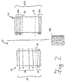
- the corresponding contents of the inactive memory 30 may be compacted as at 22b by undergoing memory defragmentation according to techniques well known to those in this art.
- connection information 22b Following compacting, the contents of the inactive memory pool 30, comprising the connection information 22b, will be expected to match those of the active memory pool 20 as shown in Figure 2.
- Each of the connections associated with the compacted connection information 24b that is respectively found at the storage locations of the inactive memory 30 labeled u', v', w' and x' will therefore correspond to each of the connections associated with the connection information 24 that is respectively found at the storage locations of the active memory 20 labeled a, b, c and d.
- each of the connections associated with the compacted connection information 26b that is respectively found at the storage locations of the inactive memory 30 labeled y' and z' will therefore correspond to each of the connections associated with the connection information 26 that is respectively found at the storage locations of the active memory 20 labeled e and f.
- This correspondence continues to be maintained in the cross-reference table 40 or the like as aforesaid.
- the use of the cross-reference table 40 allows the inactive memory 30 to be defragmented as described above while maintaining a correlation between corresponding connection information stored in each of the memory pools 20, 30.
- the contents of the active memory 20 may if desired be overwritten or otherwise replaced with the contents of the inactive memory 30.
- an activity switch is executed in order to render the inactive memory 30 into a newly active memory, which has been concurrently labeled 30A in Figure 3.
- the newly active memory 30A is thenceforth used to establish and terminate the various network connections 1 to 6, as well as others (not shown).
- the active memory 20 is therefore rendered into a newly inactive memory, which has been concurrently labeled 20A in Figure 3.
- the occurrence of the activity switch mentioned above will effectively result in more memory being made available in the newly active memory 30A, due to its larger amount of contiguous memory as compared to the newly inactive memory 20A.
- the newly inactive memory pool 20A is updated at intervals with the contents of the newly active memory pool 30A.
- the contents of the newly inactive memory pool 20A comprising the connection information 22d, will match those of the newly active memory pool 30A as shown in Figure 3.
- Each of the connections associated with the connection information 24d that is respectively found at the storage locations of the newly inactive memory 20A labeled a', b', c' and d' will therefore correspond to each of the connections associated with the connection information 24c that is respectively found at the storage locations of the newly active memory 30A labeled u', v', w' and x'.
- each of the connections associated with the connection information 26d that is respectively found at the storage locations of the newly inactive memory 20A labeled e' and f will therefore correspond to each of the connections associated with the connection information 26c that is respectively found at the storage locations of the newly active memory 30A labeled y' and z'.
- This correspondence is once again maintained in the cross-reference table 40 or the like, which maps the connections 1 to 6 in relation to the storage locations u' to z' of the connection information of the newly active memory 30A.
- the cross-reference table 40 maps the storage locations u' to z' of the connection information of the newly active memory 30A to the corresponding storage locations a' to f of the connection information of the newly inactive memory 20A. The process as explained above is then repeated for so long as the memory architecture 10 is being operated in a redundant manner.
- the active memory pool 20 of Figure 1 is partitioned as at 28 for supporting different network connection types. All things being equal, the previously defined second predetermined size of memory that is allocated to MPLS connections 5 and 6 may be expected to exhibit a higher rate of fragmentation than the first predetermined size of memory that is allocated to ATM connections 1 to 4. Those skilled in this art will appreciate that this could very well be the case in many instances since MPLS connections are associated with connection information having storage requirements that are variable in size. The assessment or measuring of fragmentation is well known to those skilled in the art. It will therefore be understood that for purposes of determining when to trigger defragmentation of the particular one of the memory pools 20, 30 that at any given time is deemed inactive, fragmentation may be assessed on the basis of the overall or aggregated memory pool in question.
- an activity switch was executed following the completion of defragmentation of the inactive memory pool 30.
- Those skilled in this art will appreciate that it may be necessary to synchronize the contents of the inactive memory 30 with the contents of the active memory pool 20 immediately following defragmentation and prior to executing the activity switch as aforesaid. This is to ensure that connection information which is stored or deleted in the active memory pool 20 during defragmentation is stored in the newly defragmented inactive memory pool 30 prior to the contents of the active memory pool 20 being lost as a result of an impending activity switch.
- the partitioning as at 28 of the active memory pool 20 in Figure 1 may result in various configurations or size allocations of partitioned memory segments.
- a first predetermined size of memory in the form of the first memory limit as defined above may, for instance, occupy 75% of each of the memory pools 20, 30.
- the second predetermined size of memory in the form of the second memory limit as defined above will therefore instead occupy 25% of each of the memory pools 20, 30. If the service mix of connection traffic in a communications switch changes such that it may become necessary to adjust the said memory limits, the present invention allows for any such adjustment to be made in relation to the inactive memory 30 as shown in Figure 2.
- the initial memory partitioning as at 28 may be readjusted as at 32 prior to executing an activity switch in order to allocate more storage to MPLS connection information relative to ATM connection information.
- the first predetermined size of memory as aforesaid may, for instance, occupy 25% of each of the memory pools following the said readjustment.
- the second predetermined size of memory as aforesaid it will therefore instead occupy 75% of each of the memory pools 20, 30 following such readjustment.
- defragmentation of the inactive memory pool 30 may take place at intervals and without being triggered by surpassing a predetermined measure of fragmentation of the active memory pool 20 as previously described. Instead, when a predetermined measure of fragmentation of the active memory pool 20 takes place, an activity switch as described previously may then ensue on the basis that the inactive memory pool 30 has been kept in an acceptably defragmented state by defragmentation which has previously occurred at intervals. Such intervals may be periodic or may even be variable based upon a level of usage of the active memory, for instance the level of connection volumes being processed at any particular time by the switching system in question.
- an activity switch between the active memory pool 20 and the inactive memory pool 30 need not necessarily follow or be triggered by the surpassing of a predetermined measure of fragmentation of the active memory pool 20 as previously described. Rather, the activity switch may be triggered by any other event. Alternatively, an activity switch need not be triggered by any event at all, and instead may take place at intervals or on demand. For instance, the activity switch may be predicated on a need to reallocate the memory partitions of the memory pools 20, 30 as previously described.
- the present invention allows for defragmentation to be performed on an inactive redundant memory, such that the in-service performance of a counterpart active memory need not be impacted.
- the redundant memory architecture as described herein also conveniently provides for a backup version of the active memory in the event of service failure.
- the present invention when the present invention is implemented in the particular shared memory architecture illustrated in Figures 1 to 3, the said architecture may be deployed to support network users who may wish to transition between two different network protocols having different traffic flow types, connection types or call types.
- the said shared memory architecture can be utilized in multi-service networks, since the network nodes or switching systems thereof must be capable of adapting to changes in the proportional distribution of traffic flow types, connection types or call types that these networks are designed to carry. It will be apparent to those versed in the art that various modifications of detail may be made to the present invention, all coming within its spirit and scope.
Landscapes
- Engineering & Computer Science (AREA)
- Theoretical Computer Science (AREA)
- Physics & Mathematics (AREA)
- General Engineering & Computer Science (AREA)
- General Physics & Mathematics (AREA)
- Data Exchanges In Wide-Area Networks (AREA)
- Hardware Redundancy (AREA)
- Techniques For Improving Reliability Of Storages (AREA)
Abstract
Description
Claims (15)
- A redundant memory architecture (10) comprising an active memory (20) supporting in-service storage operations and an inactive memory (30) that is synchronized with stored contents of the active memory, wherein stored contents of the inactive memory are defragmented prior to an activity switch which results thenceforth in the inactive memory assuming said in-service storage operations and in the active memory being updated with the stored contents of the inactive memory, the redundant memory architecture further comprising a data structure to maintain correspondence between the respective stored contents of the active memory and the inactive memory.
- The redundant memory architecture as claimed in Claim 1, wherein the contents of the inactive memory (30) are defragmented at intervals.
- The redundant memory architecture as claimed in Claim 2, wherein the contents of the inactive memory (30) are defragmented at periodic intervals.
- The redundant memory architecture as claimed in Claim 1, wherein the contents of the inactive memory (30) are defragmented upon a predetermined measure of fragmentation of the active memory being surpassed.
- The redundant memory architecture as claimed in Claim 2, wherein the contents of the inactive memory (30) are defragmented at intervals based upon a level of usage of the active memory.
- The redundant memory architecture as claimed in Claim 1, wherein the inactive memory (30) is synchronized with the stored contents of the active memory (20) at intervals.
- The redundant memory architecture as claimed in Claim 6, wherein the inactive memory (30) is synchronized with the stored contents of the active memory (20) following the stored contents of the active memory being changed.
- The redundant memory architecture as claimed in Claim 1, wherein the data structure is a cross-reference table (40).
- The redundant memory architecture as claimed in Claim 1, wherein prior to the activity switch and immediately following the contents of the inactive memory being defragmented as aforesaid, the inactive memory (30) is synchronized with the stored contents of the active memory (20).
- The redundant memory architecture as claimed in Claim 1, wherein the contents of the active memory (20) are replaced with the contents of the inactive memory (30) once the contents of the inactive memory have been defragmented as aforesaid.
- The redundant memory architecture as claimed in Claim 1, wherein the active memory (20) and the inactive memory (30) are each partitioned into memory segments.
- The redundant memory architecture as claimed in Claim 4, wherein the active memory (20) and the inactive memory (30) are each partitioned into memory segments.
- The redundant memory architecture as claimed in Claim 12, wherein the predetermined measure of fragmentation is assessed for partitioned memory segments of the active memory (20) in the aggregate.
- The redundant memory architecture as claimed in Claim 13, wherein the predetermined measure of fragmentation is assessed for partitioned memory segments of the active memory (20) separately.
- The redundant memory architecture as claimed in Claim 11, wherein the memory segments of the inactive memory (30) may be adjusted as to their size allocation following the contents of the inactive memory being defragmented as aforesaid.
Applications Claiming Priority (4)
| Application Number | Priority Date | Filing Date | Title |
|---|---|---|---|
| US810808 | 1985-12-19 | ||
| CA2455656 | 2004-01-22 | ||
| CA002455656A CA2455656A1 (en) | 2004-01-22 | 2004-01-22 | Redundant memory architecture with defragmentation capability |
| US10/810,808 US7020032B2 (en) | 2004-01-22 | 2004-03-29 | Redundant memory architecture with defragmentation capability |
Publications (2)
| Publication Number | Publication Date |
|---|---|
| EP1571554A2 true EP1571554A2 (en) | 2005-09-07 |
| EP1571554A3 EP1571554A3 (en) | 2009-07-29 |
Family
ID=34750875
Family Applications (1)
| Application Number | Title | Priority Date | Filing Date |
|---|---|---|---|
| EP20050300048 Withdrawn EP1571554A3 (en) | 2004-01-22 | 2005-01-20 | Redundant memory architecture with defragmentation capability |
Country Status (1)
| Country | Link |
|---|---|
| EP (1) | EP1571554A3 (en) |
Family Cites Families (1)
| Publication number | Priority date | Publication date | Assignee | Title |
|---|---|---|---|---|
| US6529519B1 (en) * | 1998-12-22 | 2003-03-04 | Koninklijke Philips Electronics N.V. | Prioritized-buffer management for fixed sized packets in multimedia application |
-
2005
- 2005-01-20 EP EP20050300048 patent/EP1571554A3/en not_active Withdrawn
Non-Patent Citations (1)
| Title |
|---|
| JONES R ET AL: "Garbage Collection: Algorithms for Automatic Dynamic Memory Management", 1 January 1996, GARBAGE COLLECTION : ALGORITHMS FOR AUTOMATIC DYNAMIC MEMORY MANAGEMENT, CHICHESTER, WILEY, GB, PAGE(S) 28 - 33, ISBN: 978-0-471-94148-4, XP002458141 * |
Also Published As
| Publication number | Publication date |
|---|---|
| EP1571554A3 (en) | 2009-07-29 |
Similar Documents
| Publication | Publication Date | Title |
|---|---|---|
| US20090300316A1 (en) | Computer system, management computer and storage system, and storage area allocation amount controlling method | |
| US20170177221A1 (en) | Dynamic core allocation for consistent performance in a non-preemptive scheduling environment | |
| CN1303534C (en) | Memory pool managing method | |
| JPH03180941A (en) | Method for controlling space of external storage device group | |
| CN103455433A (en) | Memory management method and system | |
| CN101799797A (en) | Dynamic allocation method of user disk quota in distributed storage system | |
| EP4611345A1 (en) | Bandwidth adjustment method, system and device, and storage medium | |
| WO2017050064A1 (en) | Memory management method and device for shared memory database | |
| US7020032B2 (en) | Redundant memory architecture with defragmentation capability | |
| CN107154966A (en) | A kind of video data wiring method and device | |
| CN104461706B (en) | A kind of method and multiprocessing device that shared global variable is shared | |
| CN115934311A (en) | A data redistribution method and electronic equipment | |
| CN110493060A (en) | A kind of virtual IP address distribution method and relevant apparatus | |
| EP1571554A2 (en) | Redundant memory architecture with defragmentation capability | |
| CN113821165A (en) | Distributed cluster fusion storage method, system and equipment | |
| CN110266790A (en) | Edge cluster management method, device, edge cluster and readable storage medium storing program for executing | |
| Barkley et al. | A lazy buddy system bounded by two coalescing delays | |
| CN1307558C (en) | Virtual internal storage allocating and managing method of subsystem in communication system | |
| CN101854398B (en) | File copy equilibrium distribution method, device and system | |
| CN105813139B (en) | Dynamic management system and method for data buffer area of uplink multiple data bearers in LTE system | |
| CN118672515A (en) | Storage system | |
| CN102123171B (en) | Storage virtualization method for mass storage management | |
| CN101923511A (en) | A memory management method and memory management system | |
| Venkatasubramanian et al. | E ective load management for scalable video servers | |
| Brimberg et al. | Allocation of queuing facilities using a minimax criterion |
Legal Events
| Date | Code | Title | Description |
|---|---|---|---|
| PUAI | Public reference made under article 153(3) epc to a published international application that has entered the european phase |
Free format text: ORIGINAL CODE: 0009012 |
|
| AK | Designated contracting states |
Kind code of ref document: A2 Designated state(s): AT BE BG CH CY CZ DE DK EE ES FI FR GB GR HU IE IS IT LI LT LU MC NL PL PT RO SE SI SK TR |
|
| AX | Request for extension of the european patent |
Extension state: AL BA HR LV MK YU |
|
| RAP1 | Party data changed (applicant data changed or rights of an application transferred) |
Owner name: ALCATEL LUCENT |
|
| PUAL | Search report despatched |
Free format text: ORIGINAL CODE: 0009013 |
|
| AK | Designated contracting states |
Kind code of ref document: A3 Designated state(s): AT BE BG CH CY CZ DE DK EE ES FI FR GB GR HU IE IS IT LI LT LU MC NL PL PT RO SE SI SK TR |
|
| AX | Request for extension of the european patent |
Extension state: AL BA HR LV MK YU |
|
| 17P | Request for examination filed |
Effective date: 20100129 |
|
| AKX | Designation fees paid |
Designated state(s): AT BE BG CH CY CZ DE DK EE ES FI FR GB GR HU IE IS IT LI LT LU MC NL PL PT RO SE SI SK TR |
|
| 17Q | First examination report despatched |
Effective date: 20100415 |
|
| RAP1 | Party data changed (applicant data changed or rights of an application transferred) |
Owner name: ALCATEL LUCENT |
|
| 111Z | Information provided on other rights and legal means of execution |
Free format text: AT BE BG CH CY CZ DE DK EE ES FI FR GB GR HU IE IS IT LI LT LU MC NL PL PT RO SE SI SK TR Effective date: 20130410 |
|
| RAP1 | Party data changed (applicant data changed or rights of an application transferred) |
Owner name: ALCATEL LUCENT |
|
| D11X | Information provided on other rights and legal means of execution (deleted) | ||
| STAA | Information on the status of an ep patent application or granted ep patent |
Free format text: STATUS: THE APPLICATION IS DEEMED TO BE WITHDRAWN |
|
| 18D | Application deemed to be withdrawn |
Effective date: 20151117 |