EP1571538A1 - Thumbwheel and switch for a mobile electronic device and corresponding method - Google Patents
Thumbwheel and switch for a mobile electronic device and corresponding method Download PDFInfo
- Publication number
- EP1571538A1 EP1571538A1 EP04004831A EP04004831A EP1571538A1 EP 1571538 A1 EP1571538 A1 EP 1571538A1 EP 04004831 A EP04004831 A EP 04004831A EP 04004831 A EP04004831 A EP 04004831A EP 1571538 A1 EP1571538 A1 EP 1571538A1
- Authority
- EP
- European Patent Office
- Prior art keywords
- thumbwheel
- approximately
- electronic device
- mobile electronic
- degrees
- Prior art date
- Legal status (The legal status is an assumption and is not a legal conclusion. Google has not performed a legal analysis and makes no representation as to the accuracy of the status listed.)
- Granted
Links
Images




Classifications
-
- G—PHYSICS
- G06—COMPUTING OR CALCULATING; COUNTING
- G06F—ELECTRIC DIGITAL DATA PROCESSING
- G06F3/00—Input arrangements for transferring data to be processed into a form capable of being handled by the computer; Output arrangements for transferring data from processing unit to output unit, e.g. interface arrangements
- G06F3/01—Input arrangements or combined input and output arrangements for interaction between user and computer
- G06F3/03—Arrangements for converting the position or the displacement of a member into a coded form
- G06F3/033—Pointing devices displaced or positioned by the user, e.g. mice, trackballs, pens or joysticks; Accessories therefor
- G06F3/038—Control and interface arrangements therefor, e.g. drivers or device-embedded control circuitry
-
- G—PHYSICS
- G06—COMPUTING OR CALCULATING; COUNTING
- G06F—ELECTRIC DIGITAL DATA PROCESSING
- G06F3/00—Input arrangements for transferring data to be processed into a form capable of being handled by the computer; Output arrangements for transferring data from processing unit to output unit, e.g. interface arrangements
- G06F3/01—Input arrangements or combined input and output arrangements for interaction between user and computer
- G06F3/03—Arrangements for converting the position or the displacement of a member into a coded form
- G06F3/033—Pointing devices displaced or positioned by the user, e.g. mice, trackballs, pens or joysticks; Accessories therefor
- G06F3/0362—Pointing devices displaced or positioned by the user, e.g. mice, trackballs, pens or joysticks; Accessories therefor with detection of one-dimensional [1D] translations or rotations of an operating part of the device, e.g. scroll wheels, sliders, knobs, rollers or belts
-
- H—ELECTRICITY
- H01—ELECTRIC ELEMENTS
- H01H—ELECTRIC SWITCHES; RELAYS; SELECTORS; EMERGENCY PROTECTIVE DEVICES
- H01H25/00—Switches with compound movement of handle or other operating part
- H01H25/008—Operating part movable both angularly and rectilinearly, the rectilinear movement being perpendicular to the axis of angular movement
-
- H—ELECTRICITY
- H01—ELECTRIC ELEMENTS
- H01H—ELECTRIC SWITCHES; RELAYS; SELECTORS; EMERGENCY PROTECTIVE DEVICES
- H01H19/00—Switches operated by an operating part which is rotatable about a longitudinal axis thereof and which is acted upon directly by a solid body external to the switch, e.g. by a hand
- H01H19/02—Details
- H01H19/10—Movable parts; Contacts mounted thereon
- H01H19/14—Operating parts, e.g. turn knob
- H01H2019/146—Roller type actuators
Definitions
- the present invention relates generally to mobile electronic devices having a thumbwheel for input.
- a thumbwheel subassembly includes a thumbwheel and a switch.
- the thumbwheel may have measurable rotation and depressible input movements, for example, rolling the thumbwheel up, rolling the thumbwheel down and pushing the thumbwheel inwards.
- a user may inadvertently roll the thumbwheel down while pushing the thumbwheel inwards.
- a method includes canceling detection of a rotation downward of a thumbwheel if detection of a depressible input movement of the thumbwheel occurs within a predetermined time threshold of detection of the rotation downward.
- the predetermined time threshold may be approximately 100 milliseconds.
- the method may be implemented by executing software instructions on a computing platform. The instructions may be stored on an article.
- a mobile electronic device includes a thumbwheel subassembly, a housing and a microprocessor inside the housing.
- the thumbwheel subassembly includes a thumbwheel and a switch.
- the housing has an opening through which the thumbwheel protrudes.
- the microprocessor is to compensate for inadvertent rolling of the thumbwheel down by a user while the user pushes the thumbwheel inwards.
- the microprocessor is to cancel detection of a rotation downward of the thumbwheel if detection of a depressible input movement of the thumbwheel occurs within a predetermined time threshold of the detection of the rotation downward.
- a mobile electronic device includes a flat display screen, a thumbwheel subassembly and a housing.
- the thumbwheel subassembly includes a thumbwheel and a switch.
- the housing has an opening through which the thumbwheel protrudes.
- the thumbwheel subassembly is oriented so that a direction of depressible input movement of the thumbwheel, when projected onto a plane substantially parallel to a plane of the flat display screen, is substantially aligned with a direction of a push by a user's thumb or finger that includes a measurable component of downward force.
- the thumbwheel subassembly is oriented so that a direction of depressible input movement of the thumbwheel, when projected onto a plane substantially parallel to a plane of the flat display screen, is at an angle in a range of approximately 2 degrees to approximately 10 degrees with respect to a direction from a first point on a side of the housing having the opening to a second point directly across from the first point on an opposite side of the housing.
- the angle may be in a range of approximately 3 degrees to approximately 8 degrees, or approximately 4 degrees to approximately 6 degrees.
- the angle may be approximately 5 degrees.
- FIG. 1 is a block diagram of an exemplary mobile electronic device, in accordance with some embodiments of the invention.
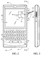
- FIG. 2 is a front view of an exemplary mobile electronic device, in accordance with some embodiments of the invention.
- FIG. 3 is a side view of the exemplary mobile electronic device of FIG. 2;
- FIG. 4 is a flowchart illustration of an exemplary method to compensate for inadvertent rolling of the thumbwheel down while pushing the thumbwheel, in accordance with some embodiments of the invention
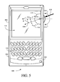
- FIG. 5 is a front view of another exemplary mobile electronic device, in accordance with some embodiments of the invention.
- FIG. 6 is a front view of a left-handed version of the exemplary mobile electronic device of FIG. 2;
- FIG. 7 is a side view of the exemplary mobile electronic device of FIG. 6.
- FIG. 8 is a front view of a left-handed version of the exemplary mobile electronic device of FIG. 5.
- FIG. 1 is a block diagram of an exemplary mobile electronic device 100, in accordance with some embodiments of the invention.
- Device 100 may be a personal data assistant (PDA), a personal information manager (PIM), a two-way pager, a cellphone, a handheld terminal, and the like.
- PDA personal data assistant
- PIM personal information manager
- device 100 may be a two-way communication device with data communication capabilities having the capability to communicate with other computer systems.
- device 100 may also include the capability for voice communications.
- Device 100 includes a microprocessor 104 that controls the overall operation of device 100, a persistent store 106, a volatile store 108, thumbwheel control logic circuitry 110, a power supply and management subsystem 112, a display screen 114, and a thumbwheel subassembly 116 coupled to thumbwheel control logic circuitry 110.
- Device 100 may optionally comprise a keyboard 120.
- Device 100 may comprise additional components (such as for example, a communications subsystem, a speaker, a microphone, etc.) that are not shown in FIG. 1 so as not to obscure the description of embodiments of the invention.
- a non-exhaustive list of examples for display screen 114 includes a liquid crystal display (LCD) screen and a thin-film-transistor (TFT) LCD screen.
- LCD liquid crystal display
- TFT thin-film-transistor
- Operating system software used by microprocessor 104 is typically stored in persistent store 106, such as, for example, flash memory or read-only memory (ROM), programmable ROM (PROM), mask ROM, electrically programmable read-only memory (EPROM), electrically erasable and programmable read only memory (EEPROM), nonvolatile random access memory (NVRAM), a magnetic or optical card, CD-ROM, and the like.
- ROM read-only memory
- PROM programmable ROM
- EPROM electrically programmable read-only memory
- EEPROM electrically erasable and programmable read only memory
- NVRAM nonvolatile random access memory
- Microprocessor 104 in addition to its operating system functions, enables execution of software applications on device 100.
- RAM random access memory
- SRAM static random access memory
- DRAM dynamic random access memory
- SDRAM synchronous dynamic random access memory
- RDRAM RAMBUS dynamic random access memory
- DDR double data rate memory
- Thumbwheel subassembly 116 may include a thumbwheel 118 and a switch 119. Thumbwheel subassembly 116 may have measurable rotation and depressible input movements, for example, rolling the thumbwheel up, rolling the thumbwheel down and pushing the thumbwheel inwards.
- a non-exhaustive list of examples for thumbwheel subassembly includes the Edge Drive Jog Encoder Type EVQWK manufactured by Panasonic and the Composite Control Switch Type SLLB from ALPS electronics.
- FIG. 2 is a front view of an exemplary mobile device 100, in accordance with some embodiments of the invention.
- display screen 114 is flat.
- Device 100 is shown in FIG. 2 in the ordinary operating/viewing position in which it would be held by and between the user's hands at the left and right side edges 202 and 204 of device 100.
- FIG. 3 is a side view of device 100.
- the housing 206 of device 100 has an opening 208 on the right side edge 204.
- Thumbwheel 118 protrudes through opening 208, which may be, for example, slot-shaped.
- Thumbwheel 118 may be in a "horizontal orientation", i.e. the circular opposite sides of thumbwheel 118 are in planes that are substantially parallel to the plane of a flat display screen 114.
- the thumbwheel may be inclined at an angle from the horizontal orientation, as shown in FIGS. 9-13 of U.S. Patent No. 6,489,950.
- thumbwheel 118 When device 100 is held as shown in FIG. 2, a user may interface with thumbwheel 118 using a thumb or index finger, for example.
- Thumbwheel 118 has an axis of rotation 215.
- the direction of a rotation upward (towards a top edge 209 of device 100) is shown in FIG. 2 as a dotted curved arrow 210.
- the direction of a rotation downward (towards a bottom edge 211 of device 100) is shown in FIG. 2 as a dotted curved arrow 212.
- thumbwheel 118 The direction of depressible input movement of thumbwheel 118 is shown in FIG. 2 as a dotted arrow 214. (If thumbwheel 118 is inclined at an angle from the horizontal orientation, then dotted arrow 214 is the projection of the direction of depressible input movement of thumbwheel 118 onto a plane substantially parallel to the plane of flat display screen 114.)
- Dotted arrow 214 is directed from a first point on right side edge 204 to a second point on left side edge 202 directly across from the first point.
- thumbwheel 118 Since pushing thumbwheel 118 is accomplished with the thumb or index finger, which pivots from below, the push may include a measurable component of downward force. For example, the push may be in the direction shown in FIG. 2 as arrow 216. In such cases, both rotation of thumbwheel downwards and the depressible input movement may be detected. Consequently, if the user intended to push thumbwheel 118 to select a particular item from a list, the next item down in the list may be selected instead inadvertently.
- FIG. 4 is a flowchart illustration of an exemplary method to compensate for inadvertent rolling of the thumbwheel down while pushing the thumbwheel, in accordance with some embodiments of the invention.
- the method is to be implemented by the software that handles detected input from thumbwheel subassembly 116. If rolling the thumbwheel down is detected (-402-), and subsequently pushing the thumbwheel in is detected (-404-), then it is checked whether the timing of the detection of rolling the thumbwheel down and the detection of pushing the thumbwheel in is too close (-406-). The time threshold may be, for example, approximately 100 milliseconds. If the timing is too close, then rolling the thumbwheel down is deemed inadvertent, and the detection of rolling the thumbwheel down is cancelled (-408-). The detected (and not cancelled) input movement of the thumbwheel is then processed (-410-).
- FIG. 5 is a front view of a device 500, in accordance with some embodiments of the invention.
- Device 500 is similar to device 100 and therefore the same reference numerals are used for components and features that are the same or similar.
- dotted arrow 214 showing the direction of depressible input movement of thumbwheel 118 in device 100
- arrow 216 showing the direction of the push by a user's thumb or finger on thumbwheel 118
- Thumbwheel subassembly 116 is oriented in device 500 so that the direction of depressible input movement of thumbwheel 118, shown as a dotted arrow 514, is at an angle B from dotted arrow 214.
- Angle B is such that the direction of depressible input movement of thumbwheel 118 (arrow 514) is substantially aligned with the direction of the push (arrow 216).
- Angle B may be in the range of approximately 2 degrees to approximately 10 degrees, or in the range of approximately 3 degrees to approximately 8 degrees, or in the range of approximately 4 degrees to approximately 6 degrees, or approximately 5 degrees.
- FIG. 6 is a front view of a left-handed version of the exemplary mobile electronic device of FIG. 2, generally referenced 600.
- FIG. 7 is a side view of the exemplary mobile electronic device 600 of FIG. 6.
- housing 206 may have an opening 608 on the left side through which thumbwheel 118 protrudes.
- the direction of depressible input movement of thumbwheel 118, or its projection onto a plane substantial parallel to the plane of flat display screen 114, is from left side edge 202 to right side edge 204. It is shown in FIG. 6 as a dotted arrow 614.
- the push may include a measurable component of downward force.
- the push may be in the direction shown in FIG. 6 as arrow 616.
- both rotation of thumbwheel downwards and the depressible input movement may be detected. Consequently, if the user intended to push thumbwheel 118 to select a particular item from a list, the next item down in the list may be selected instead inadvertently.
- FIG. 8 is a front view of a left-handed version of the exemplary mobile electronic device of FIG. 5, generally referenced 800.
- Dotted arrow 614, showing the direction of depressible input movement of thumbwheel 118 in device 600, and arrow 616, showing the direction of the push by a user's thumb or finger on thumbwheel 118, are repeated in FIG. 8.
- Thumbwheel subassembly 116 is oriented in device 800 so that the direction of depressible input movement of thumbwheel 118, shown as a dotted arrow 814, is at an angle B from dotted arrow 614.
- Angle B is such that the direction of depressible input movement of thumbwheel 118 (arrow 814) is substantially aligned with the direction of the push (arrow 616).
- Angle B may be in the range of approximately 2 degrees to approximately 10 degrees, or in the range of approximately 3 degrees to approximately 8 degrees, or in the range of approximately 4 degrees to approximately 6 degrees, or approximately 5 degrees.
Landscapes
- Engineering & Computer Science (AREA)
- General Engineering & Computer Science (AREA)
- Theoretical Computer Science (AREA)
- Human Computer Interaction (AREA)
- Physics & Mathematics (AREA)
- General Physics & Mathematics (AREA)
- Switches With Compound Operations (AREA)
- User Interface Of Digital Computer (AREA)
- Position Input By Displaying (AREA)
- Toys (AREA)
- Telephone Set Structure (AREA)
- Printers Characterized By Their Purpose (AREA)
Abstract
Description
- The present invention relates generally to mobile electronic devices having a thumbwheel for input.
- A thumbwheel subassembly includes a thumbwheel and a switch. The thumbwheel may have measurable rotation and depressible input movements, for example, rolling the thumbwheel up, rolling the thumbwheel down and pushing the thumbwheel inwards. A user may inadvertently roll the thumbwheel down while pushing the thumbwheel inwards.
- In some embodiments of the invention, a method includes canceling detection of a rotation downward of a thumbwheel if detection of a depressible input movement of the thumbwheel occurs within a predetermined time threshold of detection of the rotation downward. The predetermined time threshold may be approximately 100 milliseconds. The method may be implemented by executing software instructions on a computing platform. The instructions may be stored on an article.
- In some embodiments of the invention, a mobile electronic device includes a thumbwheel subassembly, a housing and a microprocessor inside the housing. The thumbwheel subassembly includes a thumbwheel and a switch. The housing has an opening through which the thumbwheel protrudes. The microprocessor is to compensate for inadvertent rolling of the thumbwheel down by a user while the user pushes the thumbwheel inwards. The microprocessor is to cancel detection of a rotation downward of the thumbwheel if detection of a depressible input movement of the thumbwheel occurs within a predetermined time threshold of the detection of the rotation downward.
- In some embodiments, a mobile electronic device includes a flat display screen, a thumbwheel subassembly and a housing. The thumbwheel subassembly includes a thumbwheel and a switch. The housing has an opening through which the thumbwheel protrudes. The thumbwheel subassembly is oriented so that a direction of depressible input movement of the thumbwheel, when projected onto a plane substantially parallel to a plane of the flat display screen, is substantially aligned with a direction of a push by a user's thumb or finger that includes a measurable component of downward force. In some embodiments of the invention, the thumbwheel subassembly is oriented so that a direction of depressible input movement of the thumbwheel, when projected onto a plane substantially parallel to a plane of the flat display screen, is at an angle in a range of approximately 2 degrees to approximately 10 degrees with respect to a direction from a first point on a side of the housing having the opening to a second point directly across from the first point on an opposite side of the housing. The angle may be in a range of approximately 3 degrees to approximately 8 degrees, or approximately 4 degrees to approximately 6 degrees. The angle may be approximately 5 degrees.
- Embodiments of the invention may be understood by reference to the following detailed description when read with the accompanied drawings in which:
- FIG. 1 is a block diagram of an exemplary mobile electronic device, in accordance with some embodiments of the invention;
- FIG. 2 is a front view of an exemplary mobile electronic device, in accordance with some embodiments of the invention;
- FIG. 3 is a side view of the exemplary mobile electronic device of FIG. 2;
- FIG. 4 is a flowchart illustration of an exemplary method to compensate for inadvertent rolling of the thumbwheel down while pushing the thumbwheel, in accordance with some embodiments of the invention;
- FIG. 5 is a front view of another exemplary mobile electronic device, in accordance with some embodiments of the invention;
- FIG. 6 is a front view of a left-handed version of the exemplary mobile electronic device of FIG. 2;
- FIG. 7 is a side view of the exemplary mobile electronic device of FIG. 6; and
- FIG. 8 is a front view of a left-handed version of the exemplary mobile electronic device of FIG. 5.
- It will be appreciated that for simplicity and clarity of illustration, elements shown in the figures have not necessarily been drawn to scale. For example, the dimensions of some of the elements may be exaggerated relative to other elements for clarity. Further, where considered appropriate, reference numerals may be repeated among the figures to indicate corresponding or analogous elements.
- In the following detailed description, numerous specific details are set forth in order to provide a thorough understanding of the embodiments of the invention. However it will be understood by those of ordinary skill in the art that embodiments of the invention may be practiced without these specific details. In other instances, well-known methods, procedures and components have not been described in detail so as not to obscure the invention.
- FIG. 1 is a block diagram of an exemplary mobile
electronic device 100, in accordance with some embodiments of the invention.Device 100 may be a personal data assistant (PDA), a personal information manager (PIM), a two-way pager, a cellphone, a handheld terminal, and the like. In some embodiments,device 100 may be a two-way communication device with data communication capabilities having the capability to communicate with other computer systems. In some embodiments,device 100 may also include the capability for voice communications. -
Device 100 includes amicroprocessor 104 that controls the overall operation ofdevice 100, apersistent store 106, avolatile store 108, thumbwheelcontrol logic circuitry 110, a power supply andmanagement subsystem 112, adisplay screen 114, and athumbwheel subassembly 116 coupled to thumbwheelcontrol logic circuitry 110.Device 100 may optionally comprise akeyboard 120.Device 100 may comprise additional components (such as for example, a communications subsystem, a speaker, a microphone, etc.) that are not shown in FIG. 1 so as not to obscure the description of embodiments of the invention. - A non-exhaustive list of examples for
display screen 114 includes a liquid crystal display (LCD) screen and a thin-film-transistor (TFT) LCD screen. - Operating system software used by
microprocessor 104 is typically stored inpersistent store 106, such as, for example, flash memory or read-only memory (ROM), programmable ROM (PROM), mask ROM, electrically programmable read-only memory (EPROM), electrically erasable and programmable read only memory (EEPROM), nonvolatile random access memory (NVRAM), a magnetic or optical card, CD-ROM, and the like.Microprocessor 104, in addition to its operating system functions, enables execution of software applications ondevice 100. The operating system, specific device applications, or parts thereof, may be temporarily loaded intovolatile store 108, such as for example, random access memory (RAM), static random access memory (SRAM), dynamic random access memory (DRAM), synchronous dynamic random access memory (SDRAM), RAMBUS dynamic random access memory (RDRAM), double data rate (DDR) memory, and the like. - Thumbwheel
subassembly 116 may include athumbwheel 118 and aswitch 119.Thumbwheel subassembly 116 may have measurable rotation and depressible input movements, for example, rolling the thumbwheel up, rolling the thumbwheel down and pushing the thumbwheel inwards. A non-exhaustive list of examples for thumbwheel subassembly includes the Edge Drive Jog Encoder Type EVQWK manufactured by Panasonic and the Composite Control Switch Type SLLB from ALPS electronics. - FIG. 2 is a front view of an exemplary
mobile device 100, in accordance with some embodiments of the invention. In the example shown in FIG. 2,display screen 114 is flat.Device 100 is shown in FIG. 2 in the ordinary operating/viewing position in which it would be held by and between the user's hands at the left andright side edges device 100. FIG. 3 is a side view ofdevice 100. - The
housing 206 ofdevice 100 has an opening 208 on theright side edge 204.
Thumbwheel 118 protrudes through opening 208, which may be, for example, slot-shaped. Thumbwheel 118 may be in a "horizontal orientation", i.e. the circular opposite sides ofthumbwheel 118 are in planes that are substantially parallel to the plane of aflat display screen 114. Alternatively, the thumbwheel may be inclined at an angle from the horizontal orientation, as shown in FIGS. 9-13 of U.S. Patent No. 6,489,950. - When
device 100 is held as shown in FIG. 2, a user may interface withthumbwheel 118 using a thumb or index finger, for example. Thumbwheel 118 has an axis ofrotation 215. The direction of a rotation upward (towards atop edge 209 of device 100) is shown in FIG. 2 as a dottedcurved arrow 210. The direction of a rotation downward (towards abottom edge 211 of device 100) is shown in FIG. 2 as a dottedcurved arrow 212. - The direction of depressible input movement of
thumbwheel 118 is shown in FIG. 2 as adotted arrow 214. (Ifthumbwheel 118 is inclined at an angle from the horizontal orientation, then dottedarrow 214 is the projection of the direction of depressible input movement ofthumbwheel 118 onto a plane substantially parallel to the plane offlat display screen 114.) - Dotted
arrow 214 is directed from a first point onright side edge 204 to a second point onleft side edge 202 directly across from the first point. - Since pushing
thumbwheel 118 is accomplished with the thumb or index finger, which pivots from below, the push may include a measurable component of downward force. For example, the push may be in the direction shown in FIG. 2 asarrow 216. In such cases, both rotation of thumbwheel downwards and the depressible input movement may be detected. Consequently, if the user intended to pushthumbwheel 118 to select a particular item from a list, the next item down in the list may be selected instead inadvertently. - FIG. 4 is a flowchart illustration of an exemplary method to compensate for inadvertent rolling of the thumbwheel down while pushing the thumbwheel, in accordance with some embodiments of the invention. The method is to be implemented by the software that handles detected input from
thumbwheel subassembly 116. If rolling the thumbwheel down is detected (-402-), and subsequently pushing the thumbwheel in is detected (-404-), then it is checked whether the timing of the detection of rolling the thumbwheel down and the detection of pushing the thumbwheel in is too close (-406-).
The time threshold may be, for example, approximately 100 milliseconds. If the timing is too close, then rolling the thumbwheel down is deemed inadvertent, and the detection of rolling the thumbwheel down is cancelled (-408-). The detected (and not cancelled) input movement of the thumbwheel is then processed (-410-). - It will be appreciated by persons of ordinary skill in the art that the exemplary method of FIG. 4, or any equivalent method, may be implemented in hardware rather than in software, or in a combination of hardware and software.
- FIG. 5 is a front view of a
device 500, in accordance with some embodiments of the invention.Device 500 is similar todevice 100 and therefore the same reference numerals are used for components and features that are the same or similar. In particular, dottedarrow 214, showing the direction of depressible input movement ofthumbwheel 118 indevice 100, andarrow 216, showing the direction of the push by a user's thumb or finger onthumbwheel 118, are repeated in FIG. 5.Thumbwheel subassembly 116 is oriented indevice 500 so that the direction of depressible input movement ofthumbwheel 118, shown as adotted arrow 514, is at an angle B fromdotted arrow 214. Angle B is such that the direction of depressible input movement of thumbwheel 118 (arrow 514) is substantially aligned with the direction of the push (arrow 216). Angle B may be in the range of approximately 2 degrees to approximately 10 degrees, or in the range of approximately 3 degrees to approximately 8 degrees, or in the range of approximately 4 degrees to approximately 6 degrees, or approximately 5 degrees. - FIG. 6 is a front view of a left-handed version of the exemplary mobile electronic device of FIG. 2, generally referenced 600. FIG. 7 is a side view of the exemplary mobile
electronic device 600 of FIG. 6. Indevice 600,housing 206 may have anopening 608 on the left side through which thumbwheel 118 protrudes. The direction of depressible input movement ofthumbwheel 118, or its projection onto a plane substantial parallel to the plane offlat display screen 114, is fromleft side edge 202 toright side edge 204. It is shown in FIG. 6 as adotted arrow 614. - Since pushing
thumbwheel 118 is accomplished with the thumb or index finger, which pivots from below, the push may include a measurable component of downward force. For example, the push may be in the direction shown in FIG. 6 asarrow 616. In such cases, both rotation of thumbwheel downwards and the depressible input movement may be detected. Consequently, if the user intended to pushthumbwheel 118 to select a particular item from a list, the next item down in the list may be selected instead inadvertently. - The method described hereinabove with respect to FIG. 4 is equally applicable to
device 100 and todevice 600. - FIG. 8 is a front view of a left-handed version of the exemplary mobile electronic device of FIG. 5, generally referenced 800. Dotted
arrow 614, showing the direction of depressible input movement ofthumbwheel 118 indevice 600, andarrow 616, showing the direction of the push by a user's thumb or finger onthumbwheel 118, are repeated in FIG. 8.Thumbwheel subassembly 116 is oriented indevice 800 so that the direction of depressible input movement ofthumbwheel 118, shown as adotted arrow 814, is at an angle B fromdotted arrow 614. Angle B is such that the direction of depressible input movement of thumbwheel 118 (arrow 814) is substantially aligned with the direction of the push (arrow 616). Angle B may be in the range of approximately 2 degrees to approximately 10 degrees, or in the range of approximately 3 degrees to approximately 8 degrees, or in the range of approximately 4 degrees to approximately 6 degrees, or approximately 5 degrees. - While certain features of embodiments of the invention have been illustrated and described herein, many modifications, substitutions, changes, and equivalents will now occur to those of ordinary skill in the art. It is, therefore, to be understood that the appended claims are intended to cover all such modifications and changes as fall within the spirit of the invention.
Claims (11)
- A method comprising:cancelling detection of a rotation downward of a thumbwheel (118) if detection of a depressible input movement of said thumbwheel (118) occurs within a predetermined time threshold of detection of said rotation downward.
- The method of claim 1, wherein said predetermined time threshold is approximately 100 milliseconds.
- An article having stored thereon instructions, which when executed by a computing platform, result in:cancelling detection of a rotation downward of a thumbwheel (118) if detection of a depressible input movement of said thumbwheel (118) occurs within a predetermined time threshold of detection of said rotation downward.
- A mobile electronic device (100/600) comprising:a thumbwheel subassembly (116) including a thumbwheel (118) and a switch (119);a housing (206) having an opening (208/608) through which said thumbwheel (118) protrudes; anda microprocessor (104) inside said housing (206) to compensate for inadvertent rolling of said thumbwheel (118) down by a user while said user pushes said thumbwheel (118) inwards.
- The mobile electronic device (100/600) of claim 4, wherein said microprocessor (104) is to cancel detection of a rotation downward of said thumbwheel (118) if detection of a depressible input movement of said thumbwheel (118) occurs within a predetermined time threshold of detection of said rotation downward.
- The mobile electronic device (100/600) of claim 5, wherein said predetermined time threshold is approximately 100 milliseconds.
- A mobile electronic device (500/800), comprising:a flat display screen (114);a thumbwheel subassembly (116) including a thumbwheel (118) and a switch (119); anda housing (206) having an opening (208/608) through which said thumbwheel protrudes, wherein said thumbwheel subassembly (116) is oriented so that a direction (514/814) of depressible input movement of said thumbwheel (118), when projected onto a plane substantially parallel to a plane of said flat display screen (114), is substantially aligned with a direction (216/616) of a push by a user's thumb or finger that includes a measurable component of downward force.
- A mobile electronic device (500/800), comprising:a flat display screen (114);a thumbwheel subassembly (116) including a thumbwheel (118) and a switch (119); anda housing (206) having an opening (208/608) through which said thumbwheel (118) protrudes, wherein said thumbwheel subassembly (116) is oriented so that a direction (514/814) of depressible input movement of said thumbwheel (118), when projected onto a plane substantially parallel to a plane of said flat display screen (114), is at an angle (B) in a range of approximately 2 degrees to approximately 10 degrees with respect to a direction (214/614) from a first point on a side of said housing having said opening to a second point directly across from said first point on an opposite side of said housing.
- The mobile electronic device (500/800) of claim 8, wherein said angle (B) is in a range of approximately 3 degrees to approximately 8 degrees.
- The mobile electronic device (500/800) of claim 8, wherein said angle (B) is in a range of approximately 4 degrees to approximately 6 degrees.
- The mobile electronic device (500/800) of claim 8, wherein said angle (B) is approximately 5 degrees.
Priority Applications (7)
| Application Number | Priority Date | Filing Date | Title |
|---|---|---|---|
| EP07114802A EP1852773A3 (en) | 2004-03-02 | 2004-03-02 | Thumbwheel and switch for a mobile electronic device and corresponding method |
| EP05104057A EP1586985A3 (en) | 2004-03-02 | 2004-03-02 | Thumbwheel and switch for a mobile electronic device and methods thereof |
| DE602004009402T DE602004009402T2 (en) | 2004-03-02 | 2004-03-02 | Thumbwheel and switch for a mobile electronic device and method therefor |
| AT04004831T ATE375543T1 (en) | 2004-03-02 | 2004-03-02 | THUMBWHEEL AND SWITCH FOR A MOBILE ELECTRONIC DEVICE AND METHOD THEREOF |
| EP04004831A EP1571538B1 (en) | 2004-03-02 | 2004-03-02 | Thumbwheel and switch for a mobile electronic device and corresponding method |
| CA2497835A CA2497835C (en) | 2004-03-02 | 2005-02-22 | Thumbwheel and switch for a mobile electronic device and methods thereof |
| HK06102301.4A HK1080186B (en) | 2006-02-21 | Thumbwheel and switch for a mobile electronic device and corresponding method |
Applications Claiming Priority (1)
| Application Number | Priority Date | Filing Date | Title |
|---|---|---|---|
| EP04004831A EP1571538B1 (en) | 2004-03-02 | 2004-03-02 | Thumbwheel and switch for a mobile electronic device and corresponding method |
Related Child Applications (3)
| Application Number | Title | Priority Date | Filing Date |
|---|---|---|---|
| EP05104057A Division EP1586985A3 (en) | 2004-03-02 | 2004-03-02 | Thumbwheel and switch for a mobile electronic device and methods thereof |
| EP07114802A Division EP1852773A3 (en) | 2004-03-02 | 2004-03-02 | Thumbwheel and switch for a mobile electronic device and corresponding method |
| EP05104057.4 Division-Into | 2005-05-13 |
Publications (2)
| Publication Number | Publication Date |
|---|---|
| EP1571538A1 true EP1571538A1 (en) | 2005-09-07 |
| EP1571538B1 EP1571538B1 (en) | 2007-10-10 |
Family
ID=34745978
Family Applications (3)
| Application Number | Title | Priority Date | Filing Date |
|---|---|---|---|
| EP05104057A Ceased EP1586985A3 (en) | 2004-03-02 | 2004-03-02 | Thumbwheel and switch for a mobile electronic device and methods thereof |
| EP04004831A Expired - Lifetime EP1571538B1 (en) | 2004-03-02 | 2004-03-02 | Thumbwheel and switch for a mobile electronic device and corresponding method |
| EP07114802A Withdrawn EP1852773A3 (en) | 2004-03-02 | 2004-03-02 | Thumbwheel and switch for a mobile electronic device and corresponding method |
Family Applications Before (1)
| Application Number | Title | Priority Date | Filing Date |
|---|---|---|---|
| EP05104057A Ceased EP1586985A3 (en) | 2004-03-02 | 2004-03-02 | Thumbwheel and switch for a mobile electronic device and methods thereof |
Family Applications After (1)
| Application Number | Title | Priority Date | Filing Date |
|---|---|---|---|
| EP07114802A Withdrawn EP1852773A3 (en) | 2004-03-02 | 2004-03-02 | Thumbwheel and switch for a mobile electronic device and corresponding method |
Country Status (4)
| Country | Link |
|---|---|
| EP (3) | EP1586985A3 (en) |
| AT (1) | ATE375543T1 (en) |
| CA (1) | CA2497835C (en) |
| DE (1) | DE602004009402T2 (en) |
Cited By (17)
| Publication number | Priority date | Publication date | Assignee | Title |
|---|---|---|---|---|
| CN100587667C (en) * | 2007-01-23 | 2010-02-03 | 启碁科技股份有限公司 | Method for controlling trigger event of operation of joystick |
| US8089460B2 (en) | 2007-01-17 | 2012-01-03 | Wistron Neweb Corporation | Method of controlling a joystick and preventing the joystick from enabling unwanted events |
| CN110262861A (en) * | 2013-09-03 | 2019-09-20 | 苹果公司 | UI for manipulating UI objects |
| US11402968B2 (en) | 2014-09-02 | 2022-08-02 | Apple Inc. | Reduced size user in interface |
| US11435830B2 (en) | 2018-09-11 | 2022-09-06 | Apple Inc. | Content-based tactile outputs |
| US11474626B2 (en) | 2014-09-02 | 2022-10-18 | Apple Inc. | Button functionality |
| US11513675B2 (en) | 2012-12-29 | 2022-11-29 | Apple Inc. | User interface for manipulating user interface objects |
| US11720861B2 (en) | 2014-06-27 | 2023-08-08 | Apple Inc. | Reduced size user interface |
| US11733656B2 (en) | 2016-06-11 | 2023-08-22 | Apple Inc. | Configuring context-specific user interfaces |
| US11743221B2 (en) | 2014-09-02 | 2023-08-29 | Apple Inc. | Electronic message user interface |
| US11747956B2 (en) | 2014-09-02 | 2023-09-05 | Apple Inc. | Multi-dimensional object rearrangement |
| US11829576B2 (en) | 2013-09-03 | 2023-11-28 | Apple Inc. | User interface object manipulations in a user interface |
| US11893212B2 (en) | 2021-06-06 | 2024-02-06 | Apple Inc. | User interfaces for managing application widgets |
| US12001650B2 (en) | 2014-09-02 | 2024-06-04 | Apple Inc. | Music user interface |
| US12050766B2 (en) | 2013-09-03 | 2024-07-30 | Apple Inc. | Crown input for a wearable electronic device |
| US12287962B2 (en) | 2013-09-03 | 2025-04-29 | Apple Inc. | User interface for manipulating user interface objects |
| US12511021B2 (en) | 2020-09-14 | 2025-12-30 | Apple Inc. | Device management user interface |
Citations (4)
| Publication number | Priority date | Publication date | Assignee | Title |
|---|---|---|---|---|
| US5825353A (en) * | 1995-04-18 | 1998-10-20 | Will; Craig Alexander | Control of miniature personal digital assistant using menu and thumbwheel |
| EP0901262A2 (en) * | 1997-09-04 | 1999-03-10 | Nokia Mobile Phones Ltd. | Menu navigation key for a portable telephone |
| EP1143327A1 (en) * | 2000-04-05 | 2001-10-10 | Research In Motion Limited | Hand-held electronic device with thumbwheel |
| US6392640B1 (en) * | 1995-04-18 | 2002-05-21 | Cognitive Research & Design Corp. | Entry of words with thumbwheel by disambiguation |
Family Cites Families (2)
| Publication number | Priority date | Publication date | Assignee | Title |
|---|---|---|---|---|
| US5931873A (en) | 1996-10-04 | 1999-08-03 | Telxon Corporation | Programmable mobile device with thumb wheel |
| DE10036421A1 (en) | 2000-07-26 | 2002-02-07 | Olaf Wesler | Method for one-handed text entry into keyboardless mobile devices |
-
2004
- 2004-03-02 DE DE602004009402T patent/DE602004009402T2/en not_active Expired - Lifetime
- 2004-03-02 AT AT04004831T patent/ATE375543T1/en not_active IP Right Cessation
- 2004-03-02 EP EP05104057A patent/EP1586985A3/en not_active Ceased
- 2004-03-02 EP EP04004831A patent/EP1571538B1/en not_active Expired - Lifetime
- 2004-03-02 EP EP07114802A patent/EP1852773A3/en not_active Withdrawn
-
2005
- 2005-02-22 CA CA2497835A patent/CA2497835C/en not_active Expired - Fee Related
Patent Citations (4)
| Publication number | Priority date | Publication date | Assignee | Title |
|---|---|---|---|---|
| US5825353A (en) * | 1995-04-18 | 1998-10-20 | Will; Craig Alexander | Control of miniature personal digital assistant using menu and thumbwheel |
| US6392640B1 (en) * | 1995-04-18 | 2002-05-21 | Cognitive Research & Design Corp. | Entry of words with thumbwheel by disambiguation |
| EP0901262A2 (en) * | 1997-09-04 | 1999-03-10 | Nokia Mobile Phones Ltd. | Menu navigation key for a portable telephone |
| EP1143327A1 (en) * | 2000-04-05 | 2001-10-10 | Research In Motion Limited | Hand-held electronic device with thumbwheel |
Cited By (32)
| Publication number | Priority date | Publication date | Assignee | Title |
|---|---|---|---|---|
| US8089460B2 (en) | 2007-01-17 | 2012-01-03 | Wistron Neweb Corporation | Method of controlling a joystick and preventing the joystick from enabling unwanted events |
| CN100587667C (en) * | 2007-01-23 | 2010-02-03 | 启碁科技股份有限公司 | Method for controlling trigger event of operation of joystick |
| US11513675B2 (en) | 2012-12-29 | 2022-11-29 | Apple Inc. | User interface for manipulating user interface objects |
| US11656751B2 (en) | 2013-09-03 | 2023-05-23 | Apple Inc. | User interface for manipulating user interface objects with magnetic properties |
| CN110262861B (en) * | 2013-09-03 | 2022-08-09 | 苹果公司 | User interface for manipulating user interface objects |
| US12481420B2 (en) | 2013-09-03 | 2025-11-25 | Apple Inc. | User interface for manipulating user interface objects with magnetic properties |
| US12287962B2 (en) | 2013-09-03 | 2025-04-29 | Apple Inc. | User interface for manipulating user interface objects |
| US12050766B2 (en) | 2013-09-03 | 2024-07-30 | Apple Inc. | Crown input for a wearable electronic device |
| US11829576B2 (en) | 2013-09-03 | 2023-11-28 | Apple Inc. | User interface object manipulations in a user interface |
| CN110262861A (en) * | 2013-09-03 | 2019-09-20 | 苹果公司 | UI for manipulating UI objects |
| US12361388B2 (en) | 2014-06-27 | 2025-07-15 | Apple Inc. | Reduced size user interface |
| US11720861B2 (en) | 2014-06-27 | 2023-08-08 | Apple Inc. | Reduced size user interface |
| US12299642B2 (en) | 2014-06-27 | 2025-05-13 | Apple Inc. | Reduced size user interface |
| US11743221B2 (en) | 2014-09-02 | 2023-08-29 | Apple Inc. | Electronic message user interface |
| US11747956B2 (en) | 2014-09-02 | 2023-09-05 | Apple Inc. | Multi-dimensional object rearrangement |
| US12443329B2 (en) | 2014-09-02 | 2025-10-14 | Apple Inc. | Multi-dimensional object rearrangement |
| US11941191B2 (en) | 2014-09-02 | 2024-03-26 | Apple Inc. | Button functionality |
| US12001650B2 (en) | 2014-09-02 | 2024-06-04 | Apple Inc. | Music user interface |
| US11644911B2 (en) | 2014-09-02 | 2023-05-09 | Apple Inc. | Button functionality |
| US12118181B2 (en) | 2014-09-02 | 2024-10-15 | Apple Inc. | Reduced size user interface |
| US12197659B2 (en) | 2014-09-02 | 2025-01-14 | Apple Inc. | Button functionality |
| US11474626B2 (en) | 2014-09-02 | 2022-10-18 | Apple Inc. | Button functionality |
| US12333124B2 (en) | 2014-09-02 | 2025-06-17 | Apple Inc. | Music user interface |
| US11402968B2 (en) | 2014-09-02 | 2022-08-02 | Apple Inc. | Reduced size user in interface |
| US11733656B2 (en) | 2016-06-11 | 2023-08-22 | Apple Inc. | Configuring context-specific user interfaces |
| US12228889B2 (en) | 2016-06-11 | 2025-02-18 | Apple Inc. | Configuring context-specific user interfaces |
| US11921926B2 (en) | 2018-09-11 | 2024-03-05 | Apple Inc. | Content-based tactile outputs |
| US12277275B2 (en) | 2018-09-11 | 2025-04-15 | Apple Inc. | Content-based tactile outputs |
| US11435830B2 (en) | 2018-09-11 | 2022-09-06 | Apple Inc. | Content-based tactile outputs |
| US12511021B2 (en) | 2020-09-14 | 2025-12-30 | Apple Inc. | Device management user interface |
| US12287957B2 (en) | 2021-06-06 | 2025-04-29 | Apple Inc. | User interfaces for managing application widgets |
| US11893212B2 (en) | 2021-06-06 | 2024-02-06 | Apple Inc. | User interfaces for managing application widgets |
Also Published As
| Publication number | Publication date |
|---|---|
| EP1852773A3 (en) | 2008-03-26 |
| DE602004009402D1 (en) | 2007-11-22 |
| CA2497835C (en) | 2013-12-31 |
| DE602004009402T2 (en) | 2008-07-24 |
| ATE375543T1 (en) | 2007-10-15 |
| EP1586985A3 (en) | 2005-12-21 |
| EP1571538B1 (en) | 2007-10-10 |
| CA2497835A1 (en) | 2005-09-02 |
| EP1586985A2 (en) | 2005-10-19 |
| EP1852773A2 (en) | 2007-11-07 |
| HK1080186A1 (en) | 2006-04-21 |
Similar Documents
| Publication | Publication Date | Title |
|---|---|---|
| US20080096612A1 (en) | Thumbwheel and switch for a mobile electronic device and methods thereof | |
| CA2497835C (en) | Thumbwheel and switch for a mobile electronic device and methods thereof | |
| US12022022B2 (en) | Adaptive grip suppression within curved display edges | |
| US9348455B2 (en) | Display apparatus, display control method, and program | |
| US8859971B2 (en) | Light redirection in optical navigation | |
| KR102199806B1 (en) | Electronic device with curved display module and operating method thereof | |
| EP3317744A1 (en) | Multistage friction hinge | |
| US20130278514A1 (en) | Touch screen panel and manufacturing method thereof | |
| US10602627B2 (en) | Key device of electronic device | |
| US8195123B2 (en) | Call origination method for full-touch screen portable terminal | |
| EP3418938A1 (en) | Electronic device including display and method of applying privacy filter | |
| US20180181257A1 (en) | Method for user interface of foldable display apparatus | |
| TWI291117B (en) | A tapping operation method and a mobile electrical apparatus with tapping operation function | |
| CN106775160A (en) | A kind of many application switching controls of terminal and method | |
| HK1083135A (en) | Thumbwheel and switch for a mobile electronic device and methods thereof | |
| HK1110408A (en) | Thumbwheel and switch for a mobile electronic device and corresponding method | |
| CN106484105A (en) | A kind of method and device realizing gesture identification | |
| JP5875937B2 (en) | Portable electronic device and input method | |
| US20210274035A1 (en) | Method for anti-disturbing, electronic device, and computer-readable storage medium | |
| US9947296B2 (en) | Display device, display method, program | |
| HK1080186B (en) | Thumbwheel and switch for a mobile electronic device and corresponding method | |
| US20110024276A1 (en) | Keyboard assembly for a mobile device | |
| CN106599639A (en) | Terminal screen unlocking apparatus and method | |
| CN106559578B (en) | A kind of terminal screen goes out the method and device of screen | |
| US20250193509A1 (en) | Electronic device, position-influencing interaction method for floating window and non-transitory computer readable medium |
Legal Events
| Date | Code | Title | Description |
|---|---|---|---|
| PUAI | Public reference made under article 153(3) epc to a published international application that has entered the european phase |
Free format text: ORIGINAL CODE: 0009012 |
|
| 17P | Request for examination filed |
Effective date: 20040326 |
|
| AK | Designated contracting states |
Kind code of ref document: A1 Designated state(s): AT BE BG CH CY CZ DE DK EE ES FI FR GB GR HU IE IT LI LU MC NL PL PT RO SE SI SK TR |
|
| AX | Request for extension of the european patent |
Extension state: AL LT LV MK |
|
| REG | Reference to a national code |
Ref country code: HK Ref legal event code: DE Ref document number: 1080186 Country of ref document: HK |
|
| AKX | Designation fees paid |
Designated state(s): AT BE BG CH CY CZ DE DK EE ES FI FR GB GR HU IE IT LI LU MC NL PL PT RO SE SI SK TR |
|
| AXX | Extension fees paid |
Extension state: MK Payment date: 20040326 Extension state: AL Payment date: 20040326 Extension state: LT Payment date: 20040326 Extension state: LV Payment date: 20040326 |
|
| GRAP | Despatch of communication of intention to grant a patent |
Free format text: ORIGINAL CODE: EPIDOSNIGR1 |
|
| GRAS | Grant fee paid |
Free format text: ORIGINAL CODE: EPIDOSNIGR3 |
|
| GRAA | (expected) grant |
Free format text: ORIGINAL CODE: 0009210 |
|
| AK | Designated contracting states |
Kind code of ref document: B1 Designated state(s): AT BE BG CH CY CZ DE DK EE ES FI FR GB GR HU IE IT LI LU MC NL PL PT RO SE SI SK TR |
|
| AX | Request for extension of the european patent |
Extension state: AL LT LV MK |
|
| REG | Reference to a national code |
Ref country code: GB Ref legal event code: FG4D |
|
| REG | Reference to a national code |
Ref country code: CH Ref legal event code: EP |
|
| REG | Reference to a national code |
Ref country code: IE Ref legal event code: FG4D |
|
| REF | Corresponds to: |
Ref document number: 602004009402 Country of ref document: DE Date of ref document: 20071122 Kind code of ref document: P |
|
| REG | Reference to a national code |
Ref country code: HK Ref legal event code: GR Ref document number: 1080186 Country of ref document: HK |
|
| NLV1 | Nl: lapsed or annulled due to failure to fulfill the requirements of art. 29p and 29m of the patents act | ||
| PG25 | Lapsed in a contracting state [announced via postgrant information from national office to epo] |
Ref country code: LI Free format text: LAPSE BECAUSE OF FAILURE TO SUBMIT A TRANSLATION OF THE DESCRIPTION OR TO PAY THE FEE WITHIN THE PRESCRIBED TIME-LIMIT Effective date: 20071010 Ref country code: SE Free format text: LAPSE BECAUSE OF FAILURE TO SUBMIT A TRANSLATION OF THE DESCRIPTION OR TO PAY THE FEE WITHIN THE PRESCRIBED TIME-LIMIT Effective date: 20080110 Ref country code: ES Free format text: LAPSE BECAUSE OF FAILURE TO SUBMIT A TRANSLATION OF THE DESCRIPTION OR TO PAY THE FEE WITHIN THE PRESCRIBED TIME-LIMIT Effective date: 20080121 Ref country code: CH Free format text: LAPSE BECAUSE OF FAILURE TO SUBMIT A TRANSLATION OF THE DESCRIPTION OR TO PAY THE FEE WITHIN THE PRESCRIBED TIME-LIMIT Effective date: 20071010 Ref country code: NL Free format text: LAPSE BECAUSE OF FAILURE TO SUBMIT A TRANSLATION OF THE DESCRIPTION OR TO PAY THE FEE WITHIN THE PRESCRIBED TIME-LIMIT Effective date: 20071010 |
|
| REG | Reference to a national code |
Ref country code: CH Ref legal event code: PL |
|
| PG25 | Lapsed in a contracting state [announced via postgrant information from national office to epo] |
Ref country code: BG Free format text: LAPSE BECAUSE OF FAILURE TO SUBMIT A TRANSLATION OF THE DESCRIPTION OR TO PAY THE FEE WITHIN THE PRESCRIBED TIME-LIMIT Effective date: 20080110 Ref country code: PL Free format text: LAPSE BECAUSE OF FAILURE TO SUBMIT A TRANSLATION OF THE DESCRIPTION OR TO PAY THE FEE WITHIN THE PRESCRIBED TIME-LIMIT Effective date: 20071010 Ref country code: PT Free format text: LAPSE BECAUSE OF FAILURE TO SUBMIT A TRANSLATION OF THE DESCRIPTION OR TO PAY THE FEE WITHIN THE PRESCRIBED TIME-LIMIT Effective date: 20080310 |
|
| PG25 | Lapsed in a contracting state [announced via postgrant information from national office to epo] |
Ref country code: AT Free format text: LAPSE BECAUSE OF FAILURE TO SUBMIT A TRANSLATION OF THE DESCRIPTION OR TO PAY THE FEE WITHIN THE PRESCRIBED TIME-LIMIT Effective date: 20071010 |
|
| ET | Fr: translation filed | ||
| PG25 | Lapsed in a contracting state [announced via postgrant information from national office to epo] |
Ref country code: CZ Free format text: LAPSE BECAUSE OF FAILURE TO SUBMIT A TRANSLATION OF THE DESCRIPTION OR TO PAY THE FEE WITHIN THE PRESCRIBED TIME-LIMIT Effective date: 20071010 Ref country code: DK Free format text: LAPSE BECAUSE OF FAILURE TO SUBMIT A TRANSLATION OF THE DESCRIPTION OR TO PAY THE FEE WITHIN THE PRESCRIBED TIME-LIMIT Effective date: 20071010 |
|
| PLBE | No opposition filed within time limit |
Free format text: ORIGINAL CODE: 0009261 |
|
| STAA | Information on the status of an ep patent application or granted ep patent |
Free format text: STATUS: NO OPPOSITION FILED WITHIN TIME LIMIT |
|
| PG25 | Lapsed in a contracting state [announced via postgrant information from national office to epo] |
Ref country code: RO Free format text: LAPSE BECAUSE OF FAILURE TO SUBMIT A TRANSLATION OF THE DESCRIPTION OR TO PAY THE FEE WITHIN THE PRESCRIBED TIME-LIMIT Effective date: 20071010 Ref country code: BE Free format text: LAPSE BECAUSE OF FAILURE TO SUBMIT A TRANSLATION OF THE DESCRIPTION OR TO PAY THE FEE WITHIN THE PRESCRIBED TIME-LIMIT Effective date: 20071010 Ref country code: SK Free format text: LAPSE BECAUSE OF FAILURE TO SUBMIT A TRANSLATION OF THE DESCRIPTION OR TO PAY THE FEE WITHIN THE PRESCRIBED TIME-LIMIT Effective date: 20071010 |
|
| 26N | No opposition filed |
Effective date: 20080711 |
|
| PG25 | Lapsed in a contracting state [announced via postgrant information from national office to epo] |
Ref country code: MC Free format text: LAPSE BECAUSE OF NON-PAYMENT OF DUE FEES Effective date: 20080331 |
|
| PG25 | Lapsed in a contracting state [announced via postgrant information from national office to epo] |
Ref country code: IE Free format text: LAPSE BECAUSE OF NON-PAYMENT OF DUE FEES Effective date: 20080303 Ref country code: EE Free format text: LAPSE BECAUSE OF FAILURE TO SUBMIT A TRANSLATION OF THE DESCRIPTION OR TO PAY THE FEE WITHIN THE PRESCRIBED TIME-LIMIT Effective date: 20071010 Ref country code: GR Free format text: LAPSE BECAUSE OF FAILURE TO SUBMIT A TRANSLATION OF THE DESCRIPTION OR TO PAY THE FEE WITHIN THE PRESCRIBED TIME-LIMIT Effective date: 20080111 |
|
| PG25 | Lapsed in a contracting state [announced via postgrant information from national office to epo] |
Ref country code: FI Free format text: LAPSE BECAUSE OF FAILURE TO SUBMIT A TRANSLATION OF THE DESCRIPTION OR TO PAY THE FEE WITHIN THE PRESCRIBED TIME-LIMIT Effective date: 20071010 |
|
| PG25 | Lapsed in a contracting state [announced via postgrant information from national office to epo] |
Ref country code: SI Free format text: LAPSE BECAUSE OF FAILURE TO SUBMIT A TRANSLATION OF THE DESCRIPTION OR TO PAY THE FEE WITHIN THE PRESCRIBED TIME-LIMIT Effective date: 20071010 |
|
| PG25 | Lapsed in a contracting state [announced via postgrant information from national office to epo] |
Ref country code: CY Free format text: LAPSE BECAUSE OF FAILURE TO SUBMIT A TRANSLATION OF THE DESCRIPTION OR TO PAY THE FEE WITHIN THE PRESCRIBED TIME-LIMIT Effective date: 20071010 |
|
| PG25 | Lapsed in a contracting state [announced via postgrant information from national office to epo] |
Ref country code: LU Free format text: LAPSE BECAUSE OF NON-PAYMENT OF DUE FEES Effective date: 20080302 Ref country code: HU Free format text: LAPSE BECAUSE OF FAILURE TO SUBMIT A TRANSLATION OF THE DESCRIPTION OR TO PAY THE FEE WITHIN THE PRESCRIBED TIME-LIMIT Effective date: 20080411 |
|
| PG25 | Lapsed in a contracting state [announced via postgrant information from national office to epo] |
Ref country code: TR Free format text: LAPSE BECAUSE OF FAILURE TO SUBMIT A TRANSLATION OF THE DESCRIPTION OR TO PAY THE FEE WITHIN THE PRESCRIBED TIME-LIMIT Effective date: 20071010 |
|
| PG25 | Lapsed in a contracting state [announced via postgrant information from national office to epo] |
Ref country code: IT Free format text: LAPSE BECAUSE OF NON-PAYMENT OF DUE FEES Effective date: 20080331 |
|
| REG | Reference to a national code |
Ref country code: DE Ref legal event code: R082 Ref document number: 602004009402 Country of ref document: DE Representative=s name: MERH-IP MATIAS ERNY REICHL HOFFMANN, DE |
|
| REG | Reference to a national code |
Ref country code: DE Ref legal event code: R081 Ref document number: 602004009402 Country of ref document: DE Owner name: BLACKBERRY LIMITED, WATERLOO, CA Free format text: FORMER OWNER: RESEARCH IN MOTION LTD., WATERLOO, ONTARIO, CA Effective date: 20140925 Ref country code: DE Ref legal event code: R082 Ref document number: 602004009402 Country of ref document: DE Representative=s name: MERH-IP MATIAS ERNY REICHL HOFFMANN, DE Effective date: 20140925 Ref country code: DE Ref legal event code: R082 Ref document number: 602004009402 Country of ref document: DE Representative=s name: MERH-IP MATIAS ERNY REICHL HOFFMANN PATENTANWA, DE Effective date: 20140925 |
|
| PGFP | Annual fee paid to national office [announced via postgrant information from national office to epo] |
Ref country code: DE Payment date: 20150327 Year of fee payment: 12 |
|
| PGFP | Annual fee paid to national office [announced via postgrant information from national office to epo] |
Ref country code: GB Payment date: 20150327 Year of fee payment: 12 |
|
| REG | Reference to a national code |
Ref country code: FR Ref legal event code: PLFP Year of fee payment: 13 |
|
| PGFP | Annual fee paid to national office [announced via postgrant information from national office to epo] |
Ref country code: FR Payment date: 20160328 Year of fee payment: 13 |
|
| REG | Reference to a national code |
Ref country code: DE Ref legal event code: R119 Ref document number: 602004009402 Country of ref document: DE |
|
| GBPC | Gb: european patent ceased through non-payment of renewal fee |
Effective date: 20160302 |
|
| PG25 | Lapsed in a contracting state [announced via postgrant information from national office to epo] |
Ref country code: DE Free format text: LAPSE BECAUSE OF NON-PAYMENT OF DUE FEES Effective date: 20161001 Ref country code: GB Free format text: LAPSE BECAUSE OF NON-PAYMENT OF DUE FEES Effective date: 20160302 |
|
| REG | Reference to a national code |
Ref country code: FR Ref legal event code: ST Effective date: 20171130 |
|
| PG25 | Lapsed in a contracting state [announced via postgrant information from national office to epo] |
Ref country code: FR Free format text: LAPSE BECAUSE OF NON-PAYMENT OF DUE FEES Effective date: 20170331 |