BACKGROUND OF THE INVENTION
1. Field of the Invention
The present invention relates to an image forming apparatus and an
image forming method positioning one of plural cartridges mounted to a
developing unit at a development position and performing a printing
operation in a specific color using toner in the cartridge.
2. Description of the Related Art
Heretofore, there have been widely known image forming
apparatuses adapted to form an image using a plurality of developer
cartridges. For instance, Japanese Unexamined Patent Publication No.
2003-215862 discloses a color image forming apparatus including a rotary
developing unit having four developer cartridges radially arranged about a
rotating shaft. In this apparatus, the rotating shaft is driven into rotation
for selectively positioning one of the four developer cartridges at a place
opposite to a latent image carrier such as a photosensitive member so as to
develop a latent image on the latent image carrier. Subsequently, the
developed image is transferred to an intermediate transfer medium. The
developing process and the transfer process are repeated the same way as
the above while switching from one developer cartridge to another,
whereby toner images of plural colors are superimposed on top of each
other to form a color image.
In the aforementioned color image forming apparatus, the four
developer cartridges contain therein toners of individually different colors
(yellow, cyan, magenta and black) so as to perform the printing operation
for color image. Therefore, there occurs a problem that in a case where
the above image forming apparatus is used for printing monochromatic
images, the above image forming apparatus runs out of the black toner
faster than an image forming apparatus dedicated to monochromatic image
printing. In order to overcome such a problem, there has been proposed
an apparatus wherein black developer cartridge(s) is(are) mounted to
place(s) where the yellow, cyan and/or magenta developer cartridge(s) are
mounted, and wherein when one of the black developer cartridges runs out
of the black toner, the developer cartridge is switched to another black
developer cartridge so as to permit the continuation of the monochromatic
printing operation (see, for example, Japanese Unexamined Patent
Publication No. 2002-351190).
SUMMARY OF THE INVENTION
By the way, in order to ensure that the images are favorably printed
using toner in a developer cartridge, it is necessary to conduct in advance a
print preparatory operation on the developer cartridge. The print
preparatory operation is typically exemplified by an optimization process
(a patch process). According to the apparatus set forth in Japanese
Unexamined Patent Publication No. 2003-215862, for example, the
optimization (patch) process (equivalent to a "condition control process"
of the present invention) is conducted at a proper time prior to the printing
operation. For example, the optimization process may be conducted
immediately after turn-on of the apparatus, after warm-up of the apparatus
or in parallel with the warm-up of the apparatus. In the optimization
process, optimum values of a developing bias and an exposure power, as
density control factors affecting the image quality, are calculated based on
detected densities of solid images or half-toned images formed as patch
images. In the execution of the printing operation, the developing bias
and the exposure power are set to the respective optimum values thus
calculated. Thus are obtained the optimum printing operation conditions.
Images of good and consistent quality may be formed by performing the
printing operation under the printing operation conditions thus optimized.
In view of the importance of the print preparatory operation, a variety of
proposals have been made on the print preparatory operation in the color
image forming apparatuses.
In contrast, the apparatus disclosed in Japanese Unexamined Patent
Publication No. 2002-351190 or the apparatus provided with a plurality of
developer cartridges containing the black toner does not give adequate
consideration to the print preparatory operation which is important in
performing the favorable printing operation.
It may be contemplated, for example, to apply the optimization
process set forth in Japanese Unexamined Patent Publication No. 2003-215862
as is to the optimization process for the cartridges mounted to the
developing unit. In other words, the optimization process is conducted on
the developer cartridge positioned at the development position while
transferring each of the cartridges mounted to the developing unit to the
development position in turn. Accordingly, in a case where the yellow,
cyan and magenta developer cartridges are all replaced by the black
developer cartridges, the optimization process is repeated in four cycles
before the printing operation is performed. In other words, the printing
operation is not able to be performed until the optimization processes on
all the developer cartridges is completed, although the printing operation is
executable when one of the developer cartridges is finished with the
optimization process. As a result, a user must wait for a long time till the
apparatus is placed in a printable state.
Further, the execution of the print preparatory operation on the
developer cartridge mounted to the developing unit does not always enable
the printing using the developer cartridge, because it is practically
impossible to perform the printing operation if, for example, a required
amount of toner for performing the printing operation does not remain in
the cartridge mounted to the developing unit. Therefore, the execution of
the print preparatory operation on the developer cartridge, which is not
usable for printing, leads to the waste of time and electric power, and is
inefficient in terms of time and economy.
The present invention has been accomplished in light of the
foregoing problem. A primary object of the invention is to bring an
image forming apparatus into a state capable of printing in a specific color
in a short time, the apparatus including a developing unit which is
mountable with a plurality of cartridges having toner of the specific color.
Another object of the invention is to increase an efficiency of printing in
the specific color.
According to a first aspect of the present invention, there is
provided an image forming apparatus, comprising: a latent image carrier
capable of carrying thereon an electrostatic latent image; a developing unit
having a plurality of cartridges which are freely mounted to and removed
from the developing unit and which contain toner of a specific color; and a
controller which performs a printing operation to selectively position one
of the cartridges mounted to the developing unit at a development position
and to develop the electrostatic latent image on the latent image carrier
using the toner in the cartridge positioned at the development position,
wherein the controller conducts a print preparatory operation only on a
priority cartridge, the print preparatory operation conducted on the
cartridge prior to the printing operation in order to enable the printing
operation by means of the cartridge, one of the cartridges mounted to the
developing unit defined as the priority cartridge.
According to a second aspect of the present invention, there is
provided an image forming method of an apparatus which comprises a
latent image carrier capable of carrying thereon an electrostatic latent
image, and a developing unit having a plurality of cartridges which are
freely mounted to and removed from the developing unit and which
contain toner of a specific color, the method comprising: a step of
executing a printing operation to selectively position one of the cartridges
mounted to the developing unit to a development position, and to develop
the electrostatic latent image on the latent image carrier using the toner in
the cartridge positioned at the development position, a step of conducting a
print preparatory operation only on a priority cartridge prior to the
execution of the printing operation, the print preparatory operation
conducted to enable the printing operation by means of the cartridge, one
of the cartridges mounted to the developing unit defined as the priority
cartridge.
The above and further objects and novel features of the invention
will more fully appear from the following detailed description when the
same is read in connection with the accompanying drawing. It is to be
expressly understood, however, that the drawing is for purpose of
illustration only and is not intended as a definition of the limits of the
invention.
BRIEF DESCRIPTION OF THE DRAWINGS
Fig. 1 is a diagram showing a preferred embodiment of an image
forming apparatus according to the present invention.
Fig. 2 is a block diagram showing an electrical arrangement of the
image forming apparatus of Fig. 1.
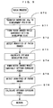
Fig. 3 is a flow chart showing a print preparatory process
conducted in the image forming apparatus of Fig. 1.
Fig. 4 is a schematic diagram showing a print preparatory
operation.
Fig. 5 is a flow chart showing an agitation process conducted in the
apparatus of Fig. 1.
Fig. 6 is a flow chart showing a patch process conducted in the
apparatus of Fig. 1.
Fig. 7 is a flow chart showing a pre-print process conducted in the
image forming apparatus of Fig. 1.
Fig. 8 is a schematic diagram showing a pre-print operation.
Fig. 9 is a flow chart showing a usable/unusable determination
process.
DETAILED DESCRIPTION OF THE PREFERRED EMBODIMENT
<First Embodiment>
Now referring to the accompanying drawings, description is made
on an embodiment of the present invention implemented in the image
forming apparatus (color printer) disclosed in Japanese Unexamined Patent
Publication No. 2003-215862. In other words, in this embodiment, the
description is made on a specific example in a single color printing or
monochromatic printing using black toner contained in four developer
cartridges.
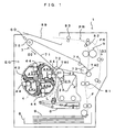
Fig. 1 is a diagram showing a preferred embodiment of an image
forming apparatus according to the present invention. Fig. 2 is a block
diagram showing an electrical arrangement of the image forming apparatus
of Fig. 1. The apparatus 1 is an image forming apparatus operative to
form monochromatic images using only the black (K) toner. In this
image forming apparatus 1, when an image signal is supplied to a main
controller 11 from an external apparatus such as a host computer, an engine
controller 10 responds to a command from the main controller 11 so as to
execute a predetermined image forming operation by controlling individual
parts of an engine section EG, thereby forming on a sheet S a
monochromatic image corresponding to the image signal.
The engine section EG is provided with a photosensitive member
22 which is rotatable in a direction D1 of an arrow in Fig. 1. A charger
unit 23, a rotary developing unit 4 and a cleaner 25 are disposed around the
photosensitive member 22 along the direction D1 of the rotation thereof.
The charger unit 23 is applied with a predetermined charging bias for
uniformly charging an outer circumferential surface of the photosensitive
member 22 to a predetermined surface potential. The cleaner 25 operates
to remove remaining toner from the surface of the photosensitive member
22 after a primary image transfer to be described hereinlater, and to collect
the removed toner in a waste toner tank disposed therein. The
photosensitive member 22, the charger unit 23 and the cleaner 25
integrally constitute a photosensitive member cartridge 2. The
photosensitive member cartridge 2, as a unit, is freely mounted to and
removed from a main body of the apparatus 1.
A light beam L from an exposure unit 6 is irradiated on the outer
circumferential surface of the photosensitive member 22 thus charged by
the charger unit 23. The exposure unit 6 irradiates the light beam L on
the photosensitive member 22 according to the image signal applied from
the external apparatus, thereby forming an electrostatic latent image
corresponding to the image signal. In the embodiment, thus, the
photosensitive member 22 is equivalent to a "latent image carrier" of the
present invention.
The electrostatic latent image thus formed is developed with toner
by means of the developing unit 4. The developing unit 4 includes a
support frame 40 freely rotatable about a rotating shaft perpendicular to the
plane of Fig. 1, four developer cartridges 4Ka to 4Kd each structured as a
cartridge free to be mounted to or removed from the support frame 40 and
each containing therein the black toner, and a rotary driver (not shown) for
driving these components into unitary rotation. The developing unit 4 is
controlled by the engine controller 10. Based on a control command
from the engine controller 10, when the developing unit 4 is driven into
rotation and any one of the developer cartridges 4Ka to 4Kd is selectively
positioned at a predetermined development position which is an abutting
position against the photosensitive member 22 or an opposed position
against the photosensitive member 22 via a predetermined gap
therebetween, a developing roller 44 disposed in the developer cartridge
thus positioned supplies the toner to the surface of the photosensitive
member 22. Thus, the electrostatic latent image on the photosensitive
member 22 is developed with the toner contained in the selected developer
cartridge (printing operation). Thus, the visualization of the electrostatic
latent image by means of the developer cartridge positioned at the
development position is equivalent to a "printing operation by means of
the cartridge" of the present invention.
The toner image developed by the developing unit 4 in the
aforementioned manner is primarily transferred onto an intermediate
transfer belt 71 of a transfer unit 7 at a primary transfer region TR1. The
transfer unit 7 includes the intermediate transfer belt 71 stretched across a
plurality of rollers 72 to 75, and a driver which drives the roller 73 into
rotation thereby revolving the intermediate transfer belt 71 in a
predetermined revolving direction D2. The transfer unit 7 forms a
monochromatic image by transferring the black toner image formed on the
photosensitive member 22 onto the intermediate transfer belt 71 and then,
secondarily transfers the monochromatic image onto a sheet S which is
picked up from a cassette 8 one by one and is transported along a
transportation path F to a secondary transfer region TR2.
In this process, timing of feeding the sheet S to the secondary
transfer region TR2 is controlled so as to transfer the image on the
intermediate transfer belt 71 onto the sheet S exactly at a predetermined
position. Specifically, a gate roller 81 is provided on the transportation
path F at a place upstream from the secondary transfer region TR2 and as
the gate roller 81 is rotated in synchronization to the timing of the
revolving movement of the intermediate transfer belt 71, the sheet S is fed
into the secondary transfer region TR2 at a predetermined timing.
Further, the sheet S now bearing the monochromatic image is
transported to a discharge tray 89, which is disposed at a top side portion
of the apparatus main body, via a fixing unit 9, a pre-discharge roller 82
and a discharge roller 83. In a case where images are formed on the both
sides of the sheet S, the rotation of the discharge roller 83 is reversed at the
point of time that a trailing end of the sheet S with the image thus formed
on one side thereof is transported to a reversal position PR downstream
from the pre-discharge roller 82. Thus, the sheet S is transported along a
reversal transport path FR in a direction of an arrow D3. Thereafter, the
sheet S is loaded again on the transportation path F at a place upstream
from the gate roller 81. At this time, the sheet S is positioned such that
the opposite side from the side to which the image is previously transferred
is to be pressed against the intermediate transfer belt 71 for image transfer
in the secondary transfer region TR2. It is possible to form images on the
both sides of the sheet S in this manner.
Further, a density sensor 60 is disposed in proximity of the roller
75. The density sensor 60 confronts a surface of the intermediate transfer
belt 71 and measures, as needed, an image density of the toner image
formed on an outside surface of the intermediate transfer belt 71. Based
on the measurement results, the apparatus adjusts the operating conditions,
for example, the developing bias applied to each developer cartridge, the
intensity of the light beam L and the like, of the individual parts thereof
which may affect the image quality.
The density sensor 60 is arranged to output a signal corresponding
to an image density of a region of a given area on the intermediate transfer
belt 71 using a reflective photosensor, for example. A CPU 101 is
adapted to detect image densities of individual parts of the toner image on
the intermediate transfer belt 71 by periodically sampling the output
signals from the density sensor 60 while moving the intermediate transfer
belt 71 in revolution.
Further, as shown in Fig. 2, the developer cartridges 4Ka to 4Kd
are provided with memories 91 to 94, respectively, each memory storing
data relating to the production lot, operation history of the developer
cartridge, the residual quantity of toner contained therein, and the like.
The developer cartridges 4Ka to 4Kd are further provided with wireless
communication devices 49Ka, 49Kb, 49Kc, 49Kd, respectively.
Whenever necessary, a selected one of these communication devices
performs non-contact data communications with a wireless communication
device 109 disposed in the main body, and the data transmission/reception
via an interface 105 is carried out between the CPU 101 and each of the
memories 91 to 94, thereby managing a variety of information items, such
as an information item on a consumable article and the like of the
developer cartridge. In the embodiment, the non-contact data
transmission/reception is carried out by using electromagnetic means such
as a wireless communication device. Alternatively, the main body and
the individual developer cartridges may be provided with connectors or the
like and a respective pair of corresponding connectors may be
mechanically fitted with each other for transmitting the data with each
other.
In Fig. 2, a reference symbol 113 represents an image memory
disposed in the main controller 11 for storing an image supplied from the
external apparatus such as a host computer via an interface 112. A
reference symbol 117 represents a RAM for temporarily storing operation
results given by a CPU 111 and other data. A reference symbol 106
represents a ROM for storing an operation program executed by the CPU
101, control data used for controlling the engine section EG, and the like.
A reference symbol 107 represents a RAM for temporarily storing
operation results given by the CPU 101 and other data.
By the way, in the apparatus arranged as described above, it is
necessary to conduct a print preparatory operation prior to the execution of
the printing operation by means of each of the developer cartridges 4Ka to
4Kd. The "print preparatory operation" means an operation or a process
to be conducted on the developer cartridges 4Ka to 4Kd prior to the
execution of the printing operation in order to enable the printing operation
by means of each of the developer cartridges 4Ka to 4Kd. In this
embodiment, the following operations and processes are conducted as the
"print preparatory operation".
(1) Mounting Confirmation Operation
The mounting confirmation operation is an operation to confirm
that the developer cartridges are assuredly mounted to the support frame
40 of the developing unit 4. Specifically, the confirmation is made based
on data transmission/reception between the CPU 101 and the individual
memories 91 to 94 via the wireless communications carried out between
the main body and the individual developer cartridges. In this respect, (2)
suitability confirmation operation to be described below is performed the
same way. It goes without saying that the mounting of the developer
cartridges may also be confirmed by means of a contact system employing
a limit switch or the like, instead of using the non-contact system like that
of the wireless communications.
(2) Suitability Confirmation Operation
The suitability confirmation operation is an operation to confirm
that the developer cartridges mounted to the support frame 40 of the
developing unit 4 are the developer cartridges containing therein the black
toner. According to the embodiment in particular, the monochromatic
image forming apparatus is constituted by mounting the black developer
cartridge(s) to mounting position(s) for yellow, cyan and/or magenta
developer cartridge(s) which are for use in the color image forming
apparatus. Accordingly, the embodiment involves a possibility of a user,
operator or the like inadvertently mounting a wrong developer cartridge.
On this account, the suitability confirmation operation is conducted to
prevent the yellow, cyan or magenta developer cartridge from being
mistakenly used.
(3) Life Confirmation Operation
The life confirmation operation is an operation to confirm that a
required amount of toner for performing the printing operation remains in
the cartridge mounted to the support frame 40 of the developing unit 4.
The occurrence of defects, such as density variations or thin spots in the
image formed by the printing operation is obviated by conducting the life
confirmation operation.
(4) Agitation Process
The agitation process is a process to cause the developing roller 44
equivalent to the "toner carrier" of the present invention to rotate at least
one round. The following is the reason for conducting the agitation
process. It has heretofore been known that the image forming apparatus
of this type may sometimes encounter the occurrence of periodical density
variations in an image when the printing operation is performed after a
long period during which the apparatus is turned off or in a standstill
where the apparatus does not perform the printing operation (image
forming operation) although the power is on. It is noted that this
phenomenon is referred to as "shutdown-induced banding phenomenon" in
this specification.
The shutdown-induced banding phenomenon is thought to result
from the fact that since the toner is left to stand for long hours being
carried on the developing roller 44 of each developer cartridge, the toner
becomes inseparable from the developing roller 44, and besides, the toner
on a surface of the developing roller 44 exhibits various degrees of
inseparability so that the toner layer on the developing roller 44 is
gradually varied in thickness. Consequently, in the image forming
apparatus of this embodiment, an "agitation demanding" signal is
generated to cause the developing roller 44 to idle when a condition of
arising the shutdown-induced banding phenomenon is satisfied, like when
the duration of the standstill exceeds a predetermined time period.
Specifically, a rotary driver (not shown) in the main body causes the
developing roller 44 to rotate at least one round. Thus, since the toner
layer on the surface of the developing roller 44 is refreshed so that a toner
layer of a more consistent thickness may be used for the developing
process, the density variations due to the shutdown-induced banding
phenomenon are less likely to occur.
(5) Patch Process (Condition Control Process)
The patch process is an optimization process to adjust a printing
operation condition to a predetermined optimum condition, the printing
operation condition under which the printing operation is performed by
means of the developing cartridge. This process is the same as those that
have heretofore been used widely in the art for stabilizing the image
quality. In this embodiment, a "patch control demanding" signal is
generated at a suitable time immediately after turn-on of the apparatus so
as to carry out the patch process in parallel with the warm-up of the
apparatus. In addition, the "patch control demanding" signal is also
generated at time when the sleep mode is cancelled, when an opened
apparatus cover is closed, or when an operation of replacing the developer
cartridge is completed, thus demanding the execution of the patch process.
Next, a print preparatory process conducted prior to the printing
process in the apparatus shown in Fig. 1 is described with reference to Figs.
3 through 6. In the interest of promoting the comprehension of the
contents of the invention, the description is made on the case where, as
shown in Fig. 1, the four developer cartridges 4Ka to 4Kd are mounted to
the developing unit 4.
Fig. 3 is a flow chart showing a print preparatory process
conducted in the image forming apparatus of Fig. 1. Fig. 4 is a schematic
diagram showing the print preparatory operation. In this apparatus, at a
proper time prior to the execution of the printing operation, for example,
immediately after the turn-on of the apparatus, the CPU 101 controls the
individual parts of the apparatus based on the program stored in the ROM
106 thereby carrying out the print preparatory process shown in Fig. 3.
That is, in this embodiment, the CPU 101 functions as a "controller" of the
present invention.
First, the data transmission/reception between the CPU 101 and
each of the memories 91 to 94 is carried out via the wireless
communications, so that a variety of information items, such as the
consumable article management, relating to the individual developer
cartridges 4Ka to 4Kd are temporarily stored in the RAM 107. Based on
the information stored in the memory 107, the developer cartridge 4Ka,
located closest to the development position among the mounted cartridges
4Ka to 4Kd, is defined as a "priority cartridge" of the present invention.
Then, the mounting confirmation operation (Step S1), the suitability
confirmation operation (Step S2) and the life confirmation operation (Step
S3) are conducted on the developer cartridge 4Ka (column (a) of Fig. 4).
In Step S4, determination is made as to whether the "agitation
demanding" signal is generated or not. This is a process for preventing
the shutdown-induced banding phenomenon. Therefore, if the "agitation
demanding" signal is not generated, the control proceeds to Step S6, and if
the signal is generated on the other hand, the agitation process shown in
Fig. 5 is conducted on the developer cartridge 4Ka (Step S5).
Fig. 5 is a flow chart showing the agitation process conducted in
the apparatus of Fig. 1. In the agitation process, the cartridge 4Ka of the
four developer cartridges is transferred to the development position as
shown in column (b) of Fig. 4 (Step S51). This brings the developing
roller 44 (DR in column (b) of Fig. 4) of the developer cartridge 4Ka into
mechanical connection with the rotary driver in the main body. The
rotary driver causes the developing roller 44 to rotate at least one round so
as to refresh the toner layer on the surface of the developing roller 44,
thereby conducting the agitation process on the developer cartridge 4Ka
(Step S52).
When the agitation process (Step S5) is thus completed, the control
proceeds to Step S6 to determine whether the "patch control demanding"
signal is generated or not. This is a process to adjust the printing
operation condition to the predetermined optimum condition. Therefore,
if the "patch control demanding" signal is not generated, after the
developing unit 4 is transferred to HP (Step S8), the print preparatory
process is terminated, and if the signal is generated on the other hand, the
patch process (Step S7) shown in Fig. 6 is conducted on the developer
cartridge 4Ka.
Fig. 6 is a flow chart showing the patch process conducted in the
apparatus of Fig. 1. The patch process is a process, in order to maintain a
certain quality of the images formed by performing the printing operation,
to form individual patch images while setting the printing operation
condition varyingly in different values, to detect the image densities of the
formed images, and to adjust the printing operation condition based on the
detection results. In this patch process, out of the operation parameters
which determine the operating conditions of the individual parts of the
apparatus, the developing bias and the exposure power, as the control
factors affecting the image quality, are adjusted. In addition to these
parameters, there are known other various operation parameters which
function as the control factors. Since there are a large number of known
techniques relating to the principles of the image quality control and the
control method using these operation parameters, only the flow of the
process is briefly described here.
Firstly, with respect to the developer cartridge 4Ka, an optimum
developing bias or an optimum value of the developing bias to be applied
to the developing roller 44 during the printing operation is calculated.
Specifically, as shown in column (b) of Fig. 4, the developer cartridge 4Ka
is selectively transferred to the development position (Step S70). While
setting the developing bias varyingly in multiple levels, each of the patch
images of a predetermined pattern is formed with each level of the
developing bias by means of the developer cartridge 4Ka (Step S71).
Then, the image density of each of the patch images is detected by means
of the density sensor 60 (Step S72).
When the image densities of the individual patch images are
determined, a corresponding relation between the developing bias and the
image density can be determined from these values. Hence, such a value
of the developing bias as to match the image density with a predetermined
target density is calculated based on the relation thus determined. Thus is
determined the optimum developing bias (Step S73). It is noted however
that if the calculated optimum value is not within a variable range of the
developing bias of the apparatus, any one of the values in the variable
range that is the closest to the calculated optimum value may be defined as
the optimum developing bias.
When the optimum developing bias for the developer cartridge 4Ka
is determined in this manner, subsequently, with respect to the developer
cartridge 4Ka, an optimum exposure power, or an optimum value of the
intensity of the light beam L in forming, on the photosensitive member 22,
an electrostatic latent image corresponding to the cartridge (Steps S274 to
S276). This process is conducted the same way as the aforementioned
process for calculating the optimum developing bias (Steps S270 to S273),
except that the control factor is the exposure power instead of the
developing bias. However, the image pattern of the patch images to be
formed may be changed to a different one, if it is necessary. It is noted
that this process may preferably set the developing bias to the previously
determined optimum value thereof. In this manner, the optimum
developing bias and the optimum exposure power for the developer
cartridge 4Ka are determined respectively and the patch process is
terminated.
By conducting such a print preparatory operation (the mounting
confirmation operation, the suitability confirmation operation, the life
confirmation operation, the agitation process, the patch process), as shown
in column (c) of Fig. 4, the developer cartridge 4Ka is placed in the
printable state in which the printing operation is conducted satisfactory.
Now returning to Fig. 3, the developing unit 4 is transferred to a home
position (HP) and stands ready (Step S8). Then, the execution of the
image forming operation by the engine section EG is permitted. The
subsequent printing operation is performed under the optimum conditions,
thereby ensuring that images of a desired image quality can be formed in a
stable manner.
Thus, according to this embodiment, prior to the printing operation,
the print preparatory operation is conducted only on the developer
cartridge 4Ka of the developer cartridges mounted to the developing unit 4,
thereby bringing the developer cartridge 4Ka into the printable state.
Accordingly, the print preparatory operation is completed when the print
preparatory operation on one cartridge (equivalent to the "priority
cartridge" of the present invention) of the developer cartridges mounted to
the developing unit 4 is terminated. Hence, the apparatus can be brought
into the printable state in a short time, which prevents the print preparatory
operation from compelling the user to wait needlessly long, so that the
user's waiting time may be shortened.
In an apparatus wherein M (M≥2) developer cartridges, less than a
mountable number, are mounted to the developing unit 4, as well, one of
these M developer cartridge may be defined as the priority cartridge so as
to conduct the print preparatory operation only on this cartridge, thereby
bringing the apparatus into a printable state in the specific color in a short
time.
Further, in the foregoing embodiments, the developer cartridge 4Ka
which is the closest to the development position is defined as the priority
cartridge and the print preparatory operation is conducted on the developer
cartridge 4Ka, but the print preparatory operation may be conducted on
any of the other developer cartridges. For instance, as described above,
since the various information items, such as the consumable article
management, relating to the developer cartridges are temporarily stored in
the RAM 107 prior to the execution of the print preparatory operation, a
developer cartridge on which the print preparatory operation is conducted,
that is the priority cartridge, may be decided based on some of these
information items.
<Second Embodiment>
By the way, in the apparatus arranged as described above, a print
preparatory operation is required to be conducted prior to the execution of
the printing operation by means of each of the developer cartridges 4Ka to
4Kd.
However, it is inefficient in terms of time and economy to conduct
the print preparatory operation on the unusable cartridge. Therefore, in
this embodiment, the cartridges mounted to the developing unit are each
checked to determine whether the cartridge is usable or not
(usable/unusable determination step) and then, the print preparatory
operation is conducted on the usable cartridges which are determined to be
usable (preparatory step). The "usable/unusable determination of
cartridge" is to determine whether the printing by means of the cartridge
becomes possible or not after the print preparatory operation is conducted
thereon. The following determination operation is conducted.
(1) Mounting Determination Operation
The mounting determination operation is an operation to determine
whether or not the developer cartridges are assuredly mounted to the
support frame 40 of the developing unit 4. Specifically, the determination
is made based on data acquired by data transmission/reception between the
CPU 101 and the individual memories 91 to 94 via the wireless
communications carried out between the main body and the individual
developer cartridges. In this respect, (2) suitability determination
operation to be described below is performed the same way. It goes
without saying that the mounting determination of the developer cartridges
may also be done by means of a contact system employing a limit switch
or the like, instead of using the non-contact system like that of the wireless
communications.
(2) Suitability Determination Operation
The suitability determination operation is an operation to determine
whether or not the developer cartridges mounted to the support frame 40 of
the developing unit 4 are the developer cartridges containing therein the
black toner. According to the embodiment in particular, the
monochromatic image forming apparatus is constituted by mounting the
black developer cartridge(s) to mounting position(s) for yellow, cyan
and/or magenta developer cartridge(s) which are for use in the color image
forming apparatus. Accordingly, the embodiment involves a possibility
of a user, operator or the like inadvertently mounting a wrong developer
cartridge. On this account, the suitability determination operation is
conducted to prevent the yellow, cyan or magenta developer cartridge from
being mistakenly used.
(3) Life Determination Operation
The life determination operation is an operation to determine
whether or not a required amount of toner for performing the printing
operation remains in the cartridge mounted to the support frame 40 of the
developing unit 4. The occurrence of defects, such as density variations
or thin spots in the image formed by the printing operation is obviated by
conducting the life determination operation.
In addition, the "print preparatory operation" means an operation or
a process to be conducted on the usable developer cartridge prior to the
execution of the printing operation in order to enable the printing operation
by means of the usable cartridge. In this embodiment, the following
processes are conducted as the "print preparatory operation".
(a) Agitation Process
The agitation process is a process to cause the developing roller 44
equivalent to the "toner carrier" of the present invention to rotate at least
one round. The reason for conducting the agitation process is described
above.
Consequently, in the image forming apparatus of this embodiment,
an "agitation demanding" signal is generated to cause the developing roller
44 to idle when a condition of arising the shutdown-induced banding
phenomenon is satisfied, like when the duration of the standstill exceeds a
predetermined time period. Specifically, a rotary driver (not shown) in
the main body causes the developing roller 44 to rotate at least one round.
Thus, since the toner layer on the surface of the developing roller 44 is
refreshed so that a toner layer of a more consistent thickness may be used
for the developing process, the density variations due to the shutdown-induced
banding phenomenon are less likely to occur.
(b) Patch Process (Condition Control Process)
The patch process is an optimization process to adjust a printing
operation condition to a predetermined optimum condition, the printing
operation condition under which the printing operation is performed by
means of the developing cartridge. This process is the same as those that
have heretofore been used widely in the art for stabilizing the image
quality. In this embodiment, a "patch control demanding" signal is
generated at a suitable time immediately after turn-on of the apparatus so
as to carry out the patch process in parallel with the warm-up of the
apparatus. In addition, the "patch control demanding" signal is also
generated at time when the sleep mode is cancelled, when an opened
apparatus cover is closed, or when an operation of replacing the developer
cartridge is completed, thus demanding the execution of the patch process.
Next, a pre-print process conducted prior to the printing process in
the apparatus shown in Fig. 1 is described with reference to Figs. 7 through
9. In the interest of promoting the comprehension of the contents of the
invention, the description is made on the case where, as shown in Fig. 1,
the four developer cartridges 4Ka to 4Kd are mounted to the developing
unit 4.
Fig. 7 is a flow chart showing a pre-print process conducted in the
image forming apparatus of Fig. 1. Fig. 8 is a schematic diagram
showing a pre-print operation. In this apparatus, at a proper time prior to
the execution of the printing operation, for example, immediately after the
turn-on of the apparatus, the CPU 101 controls the individual parts of the
apparatus according to a program stored in the ROM 106, thereby carrying
out the pre-print process (a usable/unusable determination process and a
print preparatory process) shown in Fig. 7. That is, in this embodiment,
the CPU 101 functions as a "controller" of the present invention.
First, the data transmission/reception between the CPU 101 and
each of the memories 91 to 94 is carried out via the wireless
communications, so that a variety of information items, such as the
consumable article management, relating to the individual developer
cartridges 4Ka to 4Kd are temporarily stored in the RAM 107. Then,
based on the information stored in the memory 107, the usable/unusable
determination process shown in Fig. 9 is conducted on all the developer
cartridges 4Ka to 4Kd (Step S11).
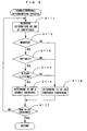
Fig. 9 is a flow chart showing the usable/unusable determination
process. In the usable/unusable determination process, the information
on one of the developer cartridges is retrieved from the memory 107 (Step
S111), then, a mounting determination operation (Step S112), a suitability
determination operation (Step S 113), and a life determination operation
(Step S 114) are conducted (column (a) of Fig. 8). A developer cartridge
having passed all the mounting determination, the suitability determination,
and the life determination is determined as a usable cartridge (Step S115),
and a developer cartridge having failed to pass any one of the above
determination operations, on the other hand, is determined as an unusable
cartridge (Step S116). Such a series of operations are repeated so long as
the result of the determination in Step S117 is "NO", thus, the
determinations are made on all the developer cartridges 4Ka to 4Kd. In
column (b) of Fig. 8, the developer cartridges 4Ka to 4Kc out of the four
developer cartridges 4Ka to 4Kd are determined as the usable cartridges,
whereas the remaining cartridge 4Kd is determined as the unusable
cartridge. Based on the determination results, the developer cartridge
4Ka that is the closest to the development position is defined as a "priority
cartridge" of the present invention, and the next print preparatory process
(Step S12 to S15) is conducted on the developer cartridge 4Ka.
In the print preparatory process, as shown in Fig. 7, determination
is made in Step S12 as to whether the "agitation demanding" signal is
generated or not. This is a process for preventing the shutdown-induced
banding phenomenon. Therefore, if the "agitation demanding" signal is
not generated, the control proceeds directly to Step S 14, and if the signal is
generated on the other hand, an agitation process (Step S13) is conducted
on the developer cartridge 4Ka. This agitation process is the same as that
conducted in the first embodiment (Step S5).
When the agitation process (Step S13) is completed, the control
proceeds to Step S 14 to determine whether the "patch control demanding"
signal is generated or not. This is a process to adjust the printing
operation condition to the predetermined optimum condition. Therefore,
if the "patch control demanding" signal is not generated, the print
preparatory process is terminated, and if the signal is generated on the
other hand, the patch process (Step S 15) is conducted on the developer
cartridge 4Ka. This patch process is the same as that conducted in the
first embodiment (Step S7).
By conducting such a print preparatory operation (the agitation
process, the patch process), as shown in column (d) of Fig. 8, the
developer cartridge 4Ka is placed in the printable state in which the
printing operation is conducted satisfactory. Then, the developing unit 4
is transferred to a home position (HP) and stands ready (Step S16). Then,
the execution of the image forming operation by the engine section EG is
permitted. The subsequent printing operation is performed under the
optimum conditions, thereby ensuring that images of a desired image
quality can be formed in a stable manner.
As described above, according to this embodiment, the cartridges
4Ka to 4Kd mounted to the developing unit are each checked to determine
whether the cartridge is usable or not prior to the execution of the printing
operation. Subsequently, one cartridge 4Ka of the usable cartridges is
defined as the priority cartridge and the print preparatory operation is
conducted only on the priority cartridge 4Ka to bring the cartridge 4Ka
into a printable state. Therefore, the print preparatory operation on the
unusable cartridge is assuredly prevented, thereby increasing the efficiency
in terms of time and economy. In addition, the print preparation is
completed when the print preparatory operation on one cartridge 4Ka of
the usable cartridges is terminated. Thus, the apparatus may be brought
into the printable state quickly, so that the print preparatory operation is
prevented from compelling the user to wait needlessly long and the user's
waiting time may be shortened.
In an apparatus wherein M (M≥2) developer cartridges, M being
less than a mountable number, are mounted to the developing unit 4, as
well, the apparatus may be brought into printable state in the specific color
in a short time by checking all of these M developer cartridges to
determine whether each of the cartridges is usable or not, defining one of
the plural cartridges determined to be usable as the priority cartridge, and
conducting the print preparatory operation only on the priority cartridge.
Further, in the above embodiment, although the usable cartridge
4Ka located closest to the development position is defined as the priority
cartridge, and on which the print preparatory operation is conducted, the
print preparatory operation may be conducted on another usable cartridge.
For instance, as described above, since the various information items, such
as the consumable article management, relating to the developer cartridges
are temporarily stored in the RAM 107 prior to the execution of the
usable/unusable determination process, the usable cartridge on which the
print preparatory operation is conducted, that is, the priority cartridge may
be decided based on some of these information items (e.g., the information
on the residual quantity of toner). Further, the cartridges may be graded
in multiple levels on the amount of toner remaining in the cartridge, and
the cartridge of a specified grade may be preferentially decided to be the
priority cartridge.
<Others>
It is to be noted that the present invention is not limited to the
foregoing embodiments and various changes and modifications other than
the above may be made thereto unless such changes and modifications
depart from the scope of the invention. For instance, in the foregoing
embodiments, up to four developer cartridges can be mounted to the
support frame 40 of the developing unit 4 and the developer cartridges 4Ka
to 4Kd are mounted to all the mounting positions, but the present invention
may be applied to an apparatus wherein the developer cartridges are
mounted to only some of the mounting positions. Further, although the
number of the mountable cartridges is four in the foregoing embodiments,
the number is arbitrary. And the number M is also arbitrary on the
condition that the number is not less than two and not more than the
number of the mountable cartridges. Therefore, the present invention is
also applicable to an image forming apparatus, for example, wherein the
developing unit 4 is designed to allow five or more developer cartridges to
be mounted to the support frame 40, wherein the yellow, cyan and magenta
developer cartridges are mounted to three mounting positions, and wherein
the black developer cartridges are mounted to the rest of the mounting
positions.
Further, in the foregoing embodiments, although the present
invention is applied to the image forming apparatus defining the specific
color as black, the specific color is not limited to this.
Further, in the foregoing embodiments, the rotary development
system is adopted wherein a plurality of developer cartridges are mounted
to the developing unit 4, so that the toner contained in the individual
developer cartridges is agitated in the cartridges in conjunction with the
rotating movement of the developing unit 4, thereby homogenizing the
toner. Consequently, toner agitation by way of the rotating operation of
the developing unit 4 may be conducted as the print preparatory operation.
Further, it has been a conventional practice to adopt a technique wherein a
member such as an agitator or an auger rod is disposed in the developer
cartridge for agitating the toner in the developer cartridge or for actively
feeding the toner to the developing roller. Consequently, in an apparatus
equipped with the member such as the agitator or the auger rod, the toner
agitation or the toner feeding by means of the member may be conducted
as the print preparatory operation.
Further, in the foregoing embodiments, although an arrangement is
adopted to use up the toner contained in the developer cartridge, in an
apparatus employing a developer cartridge of a type to be replenished with
the toner as needed, a toner replenishment operation may also be
conducted as the print preparatory operation.
Further, in the foregoing embodiments, although the four developer
cartridges 4Ka to 4Kd having the same configuration are used, it is also
possible to employ developer cartridges having configurations different
from each other. Further, in the foregoing embodiments, the present
invention is applied to the image forming apparatus of a so-called rotary
system, wherein the rotary developing unit 4 is disposed against one
photosensitive member 22, but the present invention may also be applied
to an image forming apparatus of an elevator system wherein a plurality of
developer cartridges are moved up and down relative to one photosensitive
member 22 for carrying out the development process, or an image forming
apparatus of a so-called tandem system.
Furthermore, the present invention is not limited to the
arrangements of the foregoing embodiments, but applicable to, for
example, an apparatus which is equipped with a developing unit to which a
plurality of developer cartridges having toner of a specific color are
mounted and which forms an image of the specific color, an apparatus
which is equipped with a transfer medium other than the intermediate
transfer belt (such as a transfer drum or a transfer sheet), and other image
forming apparatuses such as copiers and facsimiles.
Although the invention has been described with reference to
specific embodiments, this description is not meant to be construed in a
limiting sense. Various modifications of the disclosed embodiment, as
well as other embodiments of the present invention, will become apparent
to persons skilled in the art upon reference to the description of the
invention. It is therefore contemplated that the appended claims will
cover any such modifications or embodiments as fall within the true scope
of the invention.